![]() MLED-CTRL Box
MLED-CTRL Box
User manual
Presentation
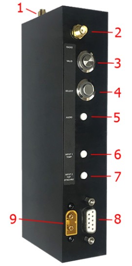
1.1. Switches and connectors
- Active GPS antenna (SMA connector)
- Radio antenna 868Mhz-915Mhz (SMA connector)
- Validation switch (Orange)
- Selection switch (Green)
- Audio out
- Input 1 / temperature sensor
- Input 2 / Sync Output
- RS232 / RS485
- Power connector (12V-24V)
Only for model with SN <= 20
If SN > 20 power connector is on the back
1.2. MLED assembly
The most common configuration comprises of 3 or 4 x MLED panels adjoined to form a display fully configurable to either a single full height line of characters or multiple lines as below. Another configuration proposed is 2 rows of 6 modules which form a 192x32cm display area.
The total display area is divided into 9 zones (A – I) as the schematic below. Be aware that some zones share the same display area and should not be used together. A line number as well as a color can be assigned to each zone via the IOS or PC setup application.
It is recommended to assign the value “0” to any unused zone.
The MLED-CTRL box must always be connected to the lower right MLED module.
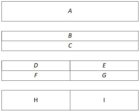
Display with 3 x MLED panels (MLED-3C):
| Zone A: | 8-9 characters, height 14-16cm depending on the font type selected |
| Zone B – C: | 16 characters per zone, height 7cm |
| Zone D – G: | 8 characters per zone, height 7cm |
| Zone H – I: | 4 characters per zone, height 14-16cm |
Display with 2×6 MLED panels (MLED-26C):
| Zone A: | 8-9 characters, height 28-32cm depending on the font type selected |
| Zone B – C: | 16 characters, height 14-16cm per zone |
| Zone D – G: | 8 characters, height 14-16cm per zone |
| Zone H – I: | 4 characters, height 28-32cm per zone |
Operating Mode
Six operating modes are available (effective for firmware version 3.0.0 and above).
- User Control via RS232, Radio or Bluetooth
- Time / Date / Temperature
- Start-Finish
- Speed trap
- Counter
- Start Clock
Modes can be selected and configured either via our mobile or PC setup application.
Modes 2-6 are optimized for MLED-3C and MLED-26C configuration. Some of them also work with MLED-1C.
2.1. User Control Mode
This is the general display mode for which you can send data from your own preferred software. Information can be displayed using either the RS232/RS485 port or Radio (using FDS / TAG Heuer protocol) or via Bluetooth using our mobile application.
This is the only mode giving full access to the display zones described in chapter 1.2.
2.2. Time / Date / Temperature Mode
Alternating time, date and temperature, all controlled via GPS and external sensors. Each of which can be pre-defined colors selected by the user for optimum and eye-catching visual impact.
The user can choose between Time, Date and Temperature or a mix of all 3 options scrolling consecutively depending on the user selection.
Temperature can be displayed in either °C or °F.
During initial power up, the displays internal time is used. If GPS is selected as the default synchro source in the settings, once a valid GPS signal is locked the information displayed is synchronized accurately.
Time of day is put on hold when a pulse on input 2 (radio or ext) is received.
TOD at Input 2 pulse is also send to RS232 and printed.
2.3. Start-Finish Mode
Start-Finish mode is a simple yet accurate mode of displaying time taken between 2 positions or inputs. This mode works either with the external Jack inputs 1 & 2 (wired solution), or with WIRC (wireless photocells) signal.
Two input sequence modes are available:
a) Sequenced mode (Normal)
– On receiving an impulse on jack input 1 or wirelessly via WIRC 1, the running time starts.
– On receiving an impulse on jack input 2 or wirelessly via WIRC 2, the time taken is displayed.
b) No sequenced mode (Any Inputs)
– Starts and Finish actions are triggered by any Inputs or WIRC.
Besides Start/Finish impulse acquisition, jack inputs 1 & 2 have two other alternate functions when using Radio inputs:
| Alternate Function | Short pulse | Long pulse |
| 1 | Block/UnBlock WIRC 1 or 2 Impulses |
Reset sequence |
| 2 | Block/UnBlock WIRC 1 and 2 Impulses |
Reset sequence |
- The Result is displayed for a predefined duration (or permanently) as per the user selected parameter.
- Jack and Radio Inputs 1&2 lock time (delay time frame) can be changed.
- WIRC wireless photocells 1 & 2 can be paired to MLED-CTRL using the Menu buttons or via our setup Apps.
- The running time / time taken can be any color pre-defined by the user.
2.4. Speed trap Mode
Speed mode is a simple yet accurate mode of displaying speed between 2 positions or inputs.
This mode works either with the external Jack inputs 1 & 2 (via a manual push button), or with WIRC (wireless photocells) signal.
Distance measured, speed color and unit displayed (Km/h, Mph, m/s, knots) and can be configured manually using the Menu Buttons or via our setup Apps.
Two input sequence modes are available:
a) Sequenced mode (Normal)
– On receiving an impulse on jack input 1 or wirelessly via WIRC 1, start time is recorded
– On receiving an impulse on jack input 2 or wirelessly via WIRC 2, finish time is recorded. Speed is then calculated (using the time difference and distance) and displayed.
b) No sequenced mode (Any Inputs)
– Start and Finish time stamps are triggered by impulses coming from any Input or WIRC.
– Speed is then calculated and displayed.
Besides impulse generation, jack inputs 1 & 2 have two other alternate functions when using Radio inputs:
| Alternate Function | Short pulse | Long pulse |
| 1 | Block/UnBlock WIRC 1 or 2 Impulses |
Reset sequence |
| 2 | Block/UnBlock WIRC 1 and 2 Impulses |
Reset sequence |
- The speed is displayed for a predefined duration (or permanently) user selectable parameter.
- Jack and Radio Inputs 1&2 lock time (delay time frame) can be changed.
- WIRC wireless photocells 1 & 2 can be paired to MLED-CTRL using the Menu buttons or via our setup Apps.
2.5. Counter Mode
- This mode works either with the external Jack inputs 1 & 2, or with WIRC signals.
- User can chose between 1 or 2 counters and several predefined counting sequences.
- For single counter, Jack input 1 or WIRC 1 is used for counting up and Jack input 2 or WIRC 2 for counting down.
- For dual counter, Jack input 1 or WIRC 1 is used for Counter 1 count up and Jack input 2 or WIRC 2 for Counter 2 count down.
- Depressing and holding for 3 seconds a jack input will reset the corresponding counter to its initial value.
- All parameters as inputs lock time, initial value, 4 digits prefix, counter color can be set using the Menu Buttons or via our setup Apps.
- WIRC 1&2 can be paired using the Menu Buttons or via our setup Apps.
- Settings allow the possibility to hide the leading ‘0’.
- If RS232 protocol is set to “DISPLAY FDS”, then each time the counter is refresh, a Display frame is send on the RS232 port.
2.6. Start-Clock Mode
This mode enables MLED Display to be used as a fully configurable start clock.
Different layouts with traffic lights, count-down value and text, can be selected according to the user defined selections.
External Jack inputs 1 & 2 control the start/stop and reset functions. Full control is also possible from our iOS App.
Guide line for a proper countdown sequence setting:
** For reference: TOD = Time of Day
- Select whether a manual countdown or automatic start at a defined TOD value is required. If TOD is selected, countdown will start before TOD value in order to reach zero at the selected TOD.
- Set the number of countdown cycles. If more than one cycle, the interval between cycles has also to be defined. For proper operation, the interval value must be greater than the sum of the countdown value and the « End of countdown time ». A value of ‘0’ means infinite number of cycles.
- Set the countdown value, initial color and color change threshold, as well as audible beep if required.
- Select the desired countdown layout (see description below).
- According to the selected layout, all other relevant parameters should be configured.
Before countdown:
After initial power-up, the display enters a “wait for synchro” state. The default synchro is defined in the settings. Other synchronization methods can be initiated via our IOS Application. Once the synchro completed, the state changes to “wait for countdown”. According the selected parameters, the Countdowns will either be started manually or automatically at a predefined time of day.
During the “wait for countdown” state, a predefined message can be displayed on the upper and lower lines as well as TOD.
During countdown:
Depending on the selected layout, information like countdown value, lights and text will be displayed. Countdown value and traffic light color will changes according to the following rules:
- When the countdown starts, the main color is defined by the parameter « Countdown Color ».
- Up to 3 color sectors can be defined. When the countdown reaches the time defined in a sector, the color changes according to the sector definition. Sector 3 has priority over sector 2 which has priority over sector 1.
- Countdown will stop at the value defined by the parameter « Countdown end time» its value can be set from 0 to 30sec after countdown reaches 0.
- When the countdown reach zero, a time frame is sent on the RS232 together with a synchro pulse.
- When the countdown end time is reached, the TOD is displayed until the next countdown.
3 audio beeps can be programmed independently. A threshold for continuous beeps (every second) can also be defined. Continuous beeps will sound until countdown reaches zero (0 will have a higher pitch and longer duration tone).
In some Layouts a text can be displayed during and at the end of the countdown. For example “GO”
2.6.1. Parameters
Countdown layouts:
A) Counter only
Full size Countdown value is displayed.
B) Counter and text
Full size countdown value is displayed until it reaches zero. On reaching zero a Text is displayed instead.
C) 5 Lights Off
Initially full size countdown value is displayed. At value = 5, five full traffic lights replace the value.
Traffic light colors are is defined according to the sectors definition. Every second a light is turned off. At zero, all lights are turned back according to the sector’s color.
D) 5 Lights On
Initially full size countdown value is displayed. At value = 5, five empty traffic lights replace the value. Traffic lights color is set according to the sectors definition. Every second a light is turned on until zero is reached.
E) Cnt 2 Lights
Full size countdown value is displayed (max 4 digits) as well as 1 traffic light on each side.
F) Cnt Text 2 Lights
Full size countdown value is displayed (max 4 digits) as well as 1 traffic light on each side. When zero is reached a text replaces the countdown.
G) TOD Cnt
Time of day is displayed on the upper left side.
A full size Countdown value is displayed (max 3 digits) on the right side.
H) TOD Cnt 5Lt Off
Time of day is displayed on upper left side.
A full size Countdown value is displayed (max 3 digits) on the right side.
When the countdown reaches 5, five full small traffic lights appear on the bottom left side under the TOD. Light colors are set according to the sectors defined. Every second a light is turned off. At zero, all lights are turned back on with sector’s color.
I) TOD Cnt 5Lt On
Time of day is displayed on upper left side.
A full size Countdown value is displayed (max 3 digits) on the right side.
When the countdown reaches 5, five empty small traffic lights appear on the bottom left side under the TOD. Light colors are set according to the sectors defined.
Every second a light is turned On until zero is reached.
J) 2 Lines Text Cnt
During countdown, the value is displayed on the bottom line with traffic lights on each side. The upper line is filled out with a user defined text.
When the countdown reach zero, the upper line changed to a second user defined text, and the countdown value on the bottom line is replaced by a third text.
K) Bib TOD Cnt
Time of day is displayed on upper left side.
A full size Countdown value is displayed (max 3 digits) or the right.
The bib number is displayed on the bottom left side under the TOD.
At the end of each cycle, the next Bib value is selected. The Bib list can be downloaded into the display via the IOS app. It is also possible to enter manually on the fly each Bib with the app.
| Start CntDown mode: | Manual start or start at defined TOD |
| Manual start sync: | Manual start can be defined to start at the next 15s, 30s or 60s. If 0 is set the countdown start immediately |
| Cycles number: | Number of countdown cycles performed automatically once the first is started (0 = non stop) |
| Cycles time interval: | Time between each countdown cycle This value must be equal or greater than the “countdown value” plus the “end of countdown time” |
| Countdown value: | Countdown time in seconds |
| Countdown color: | Initial color for countdown |
| Sector 1 time: | Start of sector 1 (compared to countdown value) |
| Sector 1 color: | Color of sector 1 |
| Sector 2 time: | Start of sector 2 (compared to countdown value) |
| Sector 2 color: | Color of sector 2 |
| Sector 3 time: | Start of sector 3 (compared to countdown value) |
| Sector 3 color: | Color of sector 3 |
| End of Countdown: | Time at which a countdown cycle is completed. Value goes from 0 to – 30sec. Sector 3 color is used |
| Beep 1 time: | Countdown time of the first beep (0 if not used) |
| Beep 2 time: | Countdown time of the second beep (0 if not used) |
| Beep 3 time: | Countdown time of the third beep (0 if not used) |
| Continuous Beep: | Countdown time at which a beep is generated every second until zero is reached |
| For Layouts (B, F, J) Final Text down: |
Text displayed in the center when countdown reaches zero |
| For Layout (J) Up text CntDwn: |
Text displayed on upper line during countdown |
| Up text at 0: | Text displayed on upper line when countdown reaches zero |
| Up text CntDwn color: | Upper line text color during countdown |
| Up text at 0 color: | Upper line text color when countdown reaches zero |
Display and Mode parameters can be defined via 2 different methods.
a) Navigating the display integrated menu using the onboard display push buttons
b) Using our iOS application
c) Using our PC application
3.1. Display Menu hierarchy
To enter the display menu, press the illuminated orange button for 3 seconds.
Once in the menu use the illuminated Green button to navigate through the menu and the illuminated Orange button to make a selection.
Depending on the mode selected or activated options status some menu items may be not visible.
Main menu:
| MODE SETTINGS | (Define the parameters of the selected mode) |
| MODE SELECTION | (Select a mode. Some modes need to be activated first with a code fromyour supplier) |
| GENERAL SETIINGS | (Display generalsettings) |
| EXT INPUTS | (Parameters of the 2 external inputs -Jack connectors) |
| RADIO | (Radio settings and WIRC wireless photocell pairing) |
| EXIT | (Leave the menu) |
General Settings:
| DISP INTENSITY | (Change the default display intensity) |
| BIG FONTS | (change the full height fonts) |
| RS232 PROTOCOL | (Select the RS232 output protocol) |
| RS232 BAUDRATE | (Select the RS232/RS485 baud rate) |
| GPS STATUS | (Display the GPS status) |
| LICENSE CODE | (Enter a license code to activate additional lodes) |
| EXIT | (Leave the menu) |
Mode Selection:
| USER CONTROL | (Standard display mode to be used with iOS App or RS232 connection) |
| TIME/TEMP/DATE | (Display the time of date, time or temperature or all three scrolling) |
| START/FINISH | (Start / Finish – With running time) |
| SPEED | (Speed trap) |
| COUNTER | (Input 1increments Counter, Input 2 decrements Counter, reset with lnput2long press) |
| SARTCLOCK | (Fully configurable Start Clock mode) |
| EXIT | (Leave the menu) |
Mode Settings (Display Mode)
| LINES ADDRESS | (Set the line number for each zone) |
| LINES COLOR | (Set the color of each zone) |
| EXIT | (Leave the menu) |
Mode Settings (Time / Temperature & Date Mode)
| DATA TO DISP | (Select what to display :temp,time,date) |
| TEMP UNITS | (Change the temperature unit·cor “F) |
| TIME COLOR | (Color of the Time value) |
| DATE COLOR | (Color of the Date) |
| TEMP COLOR | (Color of the Temperature) |
| TOD HOLD COLOR | (Color of the Time value when on hold by input 2) |
| TOD HOLD TIME | (Set the TOD holing duration) |
| SYNCH RO | (Re Synchronize the clock – Manual or GPS) |
| EXIT | (Leave the menu) |
Mode Settings (Start/Finish Mode)
| DISP HOLDING TIME | (set the time the information is displayed. 0 = always displayed) |
| COLOR | (Color of Running time and result) |
| TIME FORMAT | (Format of the time displayed) |
| INPUTS SEQUENCE | (Select the inputs sequence mode :Standard / Any Inputs) |
| INPUT 1FCN | (Function of Input 1: Std input I Auxi liary FCN 1I Auxi liary FCN 2) |
| INPUT 2 FCN | (Function of Input 2 : Std input I Auxiliary FCN 1I Auxiliary FCN 2) |
| PRINT SETTINGS | (Print the settings if RS232 Protocol is set to Printer) |
| PRINT RESULTS | (Print the time result if RS232 Protocol is set to Printer) |
| EXIT | (Leave the menu) |
Mode Settings (Speed Mode)
| DUAL COUNTER | (selection between 1and 2 counters) |
| COUNTER SEQUENCE | (counting sequence :0-9999,0-999,0-99,0-15-30-45,0-1-2-X ) |
| INITIAL VALUE | (Initial counter value after reset) |
| COUNTER PREFIX | (Prefix displayed before the counter – 4 digits max) |
| LEADING 0 | (Leave or remove the leading ‘O’) |
| PREFIX COLOR | (Color of the prefix) |
| COUNTER 1COLOR | (Color of the counter 1) |
| COUNTER 2 COLOR | (Color of the counter 2) |
| EXIT | (Leave the menu) |
Mode Settings (Start-Clock Mode)
| OFF SESSION MODE | (Select what to display when not in a countdown session) |
| START MODE | (Select between Manual and Automatic Start) |
| CYCLES NUMBER | (Number of countdown cycles: 0 = infinite) |
| CNTDOWM PARAM | (Countdown parameters menu) |
| CNTDOWM LAYOUT | (Select the way countdown info are displayed) |
| SYNCHRO | (Perform a new synchro: GPS or manual) |
| PRINT SETTINGS | (Print the settings if RS232 Protocol is set to Printer) |
| EXIT | (Leave the menu) |
CntDown Param (Start-Clock Mode)
| COUNTDOWN VALUE | (Countdown value) |
| COUNTDOWN COLOR | (Initial count down color) |
| SECTOR 1TIME | (Start time of color sector 1) |
| SECTOR 1COLOR | (Color of sector 1) |
| SECTOR 2 TIME | (Start time of color sector 2) |
| SECTOR 2 COLOR | (Color of sector 2) |
| SECTOR 3 TIME | (Start time of color sector 3) |
| SECTO R 3 COLOR | (Color of sector 3) |
| CNTDWN END TIME | (Time after countdown sequence reach zero) |
| TEXT UP >=0 COLOR | (Color of the upper text displayed in some Layout during the countdown) |
| TEXT UP = 0 COLOR | (Color of the upper text displayed in some Layout when 0 is reached) |
| BEEP 1 | (Time of Beep 1:0 = disabled) |
| BEEP 2 | (Time of Beep 2:0 = disabled) |
| BEEP 3 | (Time of Beep 3:0 = disabled) |
| CONTINUOUS BEEP | (Start time for continuous Beep: 0 = disabled) |
| EXIT | (Leave the menu) |
WIRC / WINP /WISG
WIRC, WINP or WISG can be used to send impulses in modes “Start-Finish”, “Speed trap”, “Counter”, “Count-Down”. In order to be recognized by the MLED-CTRL Box, a pairing must be performed either via the Menu Buttons or via our setup Apps.
Important:
Do not use a same WIRC/WINP/WISG on a Display and a TBox simultaneously.
4.1. Factory settings
Factory settings can be restored by pressing both Menu Buttons on MLED-CTRL during power up.
- All parameters will be reset to default.
- Bluetooth password will be reset to “0000”
- Bluetooth will be activated if previously disabled
- Bluetooth will enter DFU mode (for a firmware maintenance)
Once reset completed, power will have to be recycled (OFF/ON) in order to resume normal operation.
Connections
5.1. Power
The MLED-CTRL box can be powered from 12V to 24V. It will forward power to the connected MLED modules.
Current drawn will depend of the input voltage as well as the number of MLED panels connected.
5.2. Audio output
In some display modes, audio tones are generated on the 3.5mm stereo jack connector.
Both R & L channels are shorted together.
5.3. Input_1 / Temperature sensor Input
This 3.5mm jack connector combines 2 functionalities.
- Time capture input 1
- Digital temperature sensor input

1: External input 1
2: Temperature Sensor Data
3: GND
If temperature sensor in not used, an FDS jack to Banana cable can be used to connect an input switch.
5.4. Input_2 / Output
This 3.5mm jack connector combines 2 functionalities.
- Time capture input 2
- General purpose output (optocoupled)
1: External input 2
2: Output
3: GND

If output in not used, an FDS jack to Banana cable can be used to connect an input switch.
If output is used, a special adaptor cable is requested.
5.5. RS232/RS485
Any standard RS232 DSUB-9 cable can be used to drive the MLED-Ctrl from a computer or other compatible device. On the connector, 2 pins are reserved for RS485 connection.
DSUB-9 female pinout:
| 1 | RS485 A |
| 2 | RS232 TXD (Out) |
| 3 | RS232 RXD (In) |
| 4 | NC |
| 5 | GND |
| 6 | NC |
| 7 | NC |
| 8 | NC |
| 9 | RS485 B |
Display communication Protocol RS232/RS485
For basic text strings (no color control), the MLED-CTRL box is compatible with FDS and TAG Heuer display protocol.
6.1. Basic Format
<STX>NLXXXXXXXX<LF>
STX = 0x02
N = line number <1..9, A..K> (total 1 … 20)
L = brightness <1..3>
X = characters (up to 64)
LF = 0x0A
Format: 8bits / no parity / 1 stop bit
Baud Rate: 9600bds
6.2. Characters Set
All standard ASCII characters <32 .. 126> excepted for the char ^ which is used as delimiter
!”#$%&'()*+,-./0123456789:;<=>?@ABCDEFGHIJKLMNOPQRSTUVWXYZ
[\]_’`abcdefghijklmnopqrstuvwxyz{|}~
Extended Latin ASCII characters (ISO-8859-1) <224 .. 255>
àáâãäåæçèéêëìíîïðñòóôõö÷øùúûüýþÿ
6.3. FDS extended commands
The following specification is valid for firmware version V3.0.0 an above.
Inline commands can be add in a display frame between the ^^ delimiters.
| Command | Description | |
| ^cs c^ | Color overlay | |
| ^cp s e c^ | Color overlay between two characters position | |
| ^tf p c^ | Display a Traffic Light at position (Filled) | |
| ^tb p c^ | Display a Traffic Light at position (Border only) | |
| ^ic n c p ^ | Display an icon (among proposed icons) | |
| ^fi c^ | Fill all display | |
| ^fs n s c^ ^fe^ |
Flash part of a text | |
| ^fd n s c^ | Flash full line | |
| ^rt f hh:mm:ss^ ^rt f hh:mm:ss.d^ ^rt f mm:ss^ ^rt f mm:ss.d^ ^rt f sss^ ^rt f sss.d^ |
Display a running time | |
Color Overlay:
| Command | Description | |
| ^cs c^ | Color overlay cs = start color overlay cmd c = color code (1 or 2 digits : <0 … 10>) Example A: <STX>13Welcome ^cs 2^FDS^cs 0^Timing<LF> “Welcome” and “Timing” are in the default line color “FDS” is in Green Example B: <STX>23^cs 3^Colour^cs 4^ Display<LF> “Color” is in Blue “Display” is in Yellow Color overlay is only applied in the current received frame. |
|
Text Color at position:
| Command | Description | |
| ^cp s e c^ | Set color overlay between two characters position (permanent) cp = cmd s = first character position (1 or 2 digits : <1 .. 32>) e = last character position (1 or 2 digits : <1 .. 32>) c = color code (1 or 2 digits : <0 … 10>) Example: <STX>13^cp 1 10 2^^cp 11 16 3^ <LF> Characters position 1 to 10 are defined in Green Characters position 11 to 16 are defined in Blue This setting is saved in non-volatile memory, and is applied to all following received frame. |
|
Display a Traffic lights at position (Filled):
| Command | Description | |
| ^tf p c^ | Display a filled traffic light at a defined position tf = cmd p = position starting from the left (1 .. 9). 1 inc = 1 traffic light width c = color code (1 or 2 digits : <0 … 10>) Example: <STX>13^tf 1 2^^tf 2 1^ <LF> Display a green and a red traffic Light on the left of the display. This will overlay any other data. The rest of the display is not modified. Do not add text in the same frame |
|
Display a Traffic lights at position (Border only):
| Command | Description | |
| ^tb p c^ | Display a traffic light (border only) at a defined position tb = cmd p = position starting from the left (1 .. 9). 1 inc = 1 traffic light width c = color code (1 or 2 digits : <0 … 10>) Example: <STX>13^tb 1 2^^tb 2 1^ <LF> Display a green and a red traffic Light on the left of the display. This will overlay any other data. The rest of the display is not modified Do not add text in the same frame |
|
Display an Icon:
| Command | Description | |
| ^ic n c p^ | Display an icon inline a text or at a defined position ic = cmd c = color code (1 or 2 digits : <0 … 10>) p = position starting from the left (*optional) <1…32> 1 inc = ½ icon width Example 1: <STX>13^ic 1 2 2^<LF> Display a small green traffic light at position 2 Example 2: <STX>13^ic 5 7^Finish<LF> Display a white checker flag on the left followed by the text ‘Finish’ * If this parameter is omitted, the icon is displayed before, after or between a text. Text can be added in the same frame. If this parameter > 0 then the icon will be displayed at the defined position overlaying any other data. Do not add text in the same frame.Icon list: 0 = reserved 1 = small traffic light filled 2 = small traffic light empty 3 = traffic light filled 4 = traffic light empty 5 = Checker flag |
|
Fill all display:
| Command | Description | |
| ^fi c^ | Fill with a defined color the full display area. Only 50% of the LEDs are turned on to reduce current and heating fi = cmd c = color code (1 or 2 digits : <0 … 10>) Example: <STX>13^fi 1^ <LF> Fill the display line with the red color. |
|
Flash a full line:
| Command | Description | |
| ^fd n s c^ | Flash a full line fd = cmd s = Speed <0 … 3> n = Number of flash <0 … 9> (0 = permanent flashing) c = color code *optional (0 – 2 digits : <0 … 10>) Example: <STX>13^fd 3 1^<LF> Flash the line 3 times at speed 1 |
|
Flash a text:
| Command | Description | |
| ^fs n s c^ ^fe^ |
Flash a text fs = Start of text to flash cmd fe = End of text to flash cmd s = Speed <0 … 3> n = Number of flash <0 … 9> (0 = permanent flashing) c = color code *optional (0 – 2 digits : <0 … 10>) Example: <STX>13^fs 3 1^FDS^fe^ Timing<LF> Display the text “FDS Timing”. The word ‘FDS’ is flashing 3 times. Color is not present so Black by default. |
|
Display a running time:
| Command | Description | |
| ^rt f hh:mm:ss^ ^rt f hh:mm:ss.d^ ^rt f mm:ss^ ^rt f mm:ss.d^ ^rt f sss^ ^rt f sss.d^ |
Display a running time rt = cmd f = Flags <0 … 7> (bit0 = remove leading 0; bit1 =countdown) hh = hours <0 … 99> mm = minutes <0 … 59> sss = seconds <0 … 999> ss = seconds <0 … 59> d = decimal Example 1: <STX>13^rt 0 10:00:00^<LF> <STX>13^rt 0 10:00:00.5^<LF> Display a clock starring at 10h. A decimal can be added for a better synchronization, however if the display is 8 digits wide, the decimal is not showed. Example 2: <STX>13^rt 1 00:00.0^<LF> Display a running time in mm:ss.d from 0, hiding the leading zero. |
|
Color code:
| code | Color |
| 0 | Black |
| 1 | Red |
| 2 | Green |
| 3 | Blue |
| 4 | Yellow |
| 5 | Magenta |
| 6 | Cyan |
| 7 | White |
| 8 | Orange |
| 9 | Deep pink |
| 10 | Light Blue |
How to update the firmware
Updating the MLED-CTRL box firmware is relatively simple.
For this operation you will need to use the software “FdsFirmwareUpdate”.
a) Disconnect power from the MLED-CTRL Box
b) Install the program “FdsFirmwareUpdate” on your computer
c) Connect the RS232
d) Run the program “FdsFirmwareUpdate”
e) Select the COM Port
f) Select the update file (.bin)
g) Press Start on the program
h) Connect the power cable to MLED-CTRL Box
MLED module firmware can also be updated via the MLED-CTRL Box using the same procedure.
Firmware and apps can be found on our website: https://fdstiming.com/download/
Technical specifications
| Power supply | 12V-24V (+/- 10%) | |
| Radio frequencies & Power : Europe India North America |
869.4 – 869.65 MHz 100mW 865 – 867 MHz 100mW 920 – 924 MHz 100mW |
|
| Inputs precision | 1/10’000 sec | |
| Operating temperature | -20°C to 60°C | |
| Time drift | ppm @ 20°C; max 2.Sppm from -20°C to 60°C | |
| Bluetooth module | BLE 5 | |
| Dimensions | 160x65x35mm | |
| Weight | 280gr | |
Copyright and Declaration
This manual has been compiled with great care and the information it contains has been thoroughly verified. The text was correct at the time of printing, however the content can change without notice. FDS accepts no liability for damage resulting directly or indirectly from faults, incompleteness or discrepancies between this manual and the product described.
The sale of products, services of goods governed under this publication are covered by FDS’s standard Terms and Conditions of Sales and this product publication is provided solely for informational purposes. This publication is to be used for the standard model of the product of the type given above.
Trademarks: All hardware and software product names used in this document are likely to be registered trademarks and must be treated accordingly.
![]()
FDS-TIMING Sàrl
Rue du Nord 123
2300 La Chaux-De-Fonds
Switzerland
www.fdstiming.com
October 2024 – Version EN 1.3
www.fdstiming.com
Documents / Resources
 |
FDS TIMING SOLUTION MLED-3C Ctrl and Display Box [pdf] User Manual MLED-3C, MLED-3C Ctrl and Display Box, Ctrl and Display Box, Display Box, Box |