![]() FNI IOL-712-000-K023
FNI IOL-712-000-K023
FNI IOL-714-000-K023
User’s Guide  FAS Network Interface / 10-Link
Notes
1.1. Structure of the guide
The guide is organized so that the sections build on one another.
Section 2: Basic safety information.
1.2. Typographical conventions
The following typographical conventions are used in this guide.
Enumerations
Enumerations are shown in list form with bullet points:
- Entry1
- Entry2
Actions
Action instructions are indicated by a preceding triangle. The result of an action is indicated by an arrow.
- Action instruction 1
- Action result
- Action instruction 2
Syntax
Numbers:
Decimal numbers are shown without additional indicators (e.g. 123), Hexadecimal numbers are shown with the additional indicator hex (e.g. 00hex).
Cross references
Cross references indicate where additional information on the topic can be found.
1.3. Symbols
![]() Note
Note
This symbol indicates general notes.
![]() Attention!
Attention!
This symbol indicates a security notice which most be observed.
1.4. Abbreviations
| FNI | FAS Network Interface |
| I-Port | Standard input port |
| DPP | Direct parameter page |
| 1oL | 10-Link |
| EMC | Electromagnetic compatibility |
| FE | Function ground |
| SPDU | Service Protocol Data Unit |
1.5. Deviating views
Product views and illustrations in this user’s guide may differ from the actual product. They are intended only as illustrative material.
Safety
2.1. Intended use
This guide describes the FAS Network Interface FNI 10L-712/714-000-K023 for the application as peripheral output module to connect analogue sensors. Hereby it is about an 10-Link device which communicates by means of |O-Link protocol with the superordinate 10-Link master assembly.
2.2. Installation and startup
![]() Attention!
Attention!
Installation and startup are to be performed only by trained specialists. Qualified personnel are persons who are familiar with the installation and operation of the product, and who fulfills the qualifications required for this activity. Any damage resulting from unauthorized manipulation or improper use voids the manufacturer’s guarantee and warranty. The Operator is responsible for ensuring that applicable of safety and accident prevention regulations are complied with.
2.3. General safety notes
Commissioning and inspection
Before commissioning, carefully read the operating manual.
The system must not be used in applications in which the safety of persons is dependent on the function of the device.
Authorized Personnel
Installation and commissioning may only be performed by trained specialist personnel.
Intended use
Warranty and liability claims against the manufacturer are rendered void by:
- Unauthorized tampering
- Improper use
- Use, installation or handling contrary to the instructions provided in this operating manual
Obligations of the Operating Company
The device is a piece of equipment from EMC Class A. Such equipment may generate RF noise. The operator must take appropriate precautionary measures. The device may only be used with an approved power supply. Only approved cables may be used.
Malfunctions
In the event of defects and device malfunctions that cannot be rectified, the device must be taken out of operation and protected against unauthorized use.
Intended use is ensured only when the housing is fully installed.
2.4. Resistance to aggressive substances
![]() Attention!
Attention!
The FNI modules generally have a good chemical and oil resistance. When used in aggressive media (eg chemicals, oils, lubricants and coolants each in high concentration (ie, low water content)) must be checked prior application- related material compatibility. In the event of failure or damage to the FNI modules due to such aggressive media are no claims for defects.
Hazardous voltage
![]() Attention!
Attention!
Disconnect all power before servicing equipment.
![]() Note
Note
In the interest of product improvement, the FAS reserves the right to change the specifications of the product and the contents of this manual at any time without notice.
Getting started
3.1. Connection overview
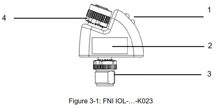
- Status LED: Supply, Communication
- Label
- 10-Link interface
- Analogue input port
3.2. Mechanical connection
To avoid long, shielded analogue cables, the FNI IOL-712/714-000-K023 modules should be attached to the analogue unit which has to be connected. No further mechanical attachment is required.
3.3. Electrical connection
The FNI IOL-712/714-000-K023 modules require no separate supply voltage connection. Power is provided through the I0-Link interface by the superordinate |0-Link Master Assembly.
3.4. 10-Link interface
10-Link (M12, A-coded, male)
| Pin | Signal | |
| 1 | Supply voltage, +24V | |
| 2 | – | |
| 3 | GND, reference potential | |
| 4 | C/Q, IO-Link Data transmission channel |
Connecting the module
» Connect the FNI IOL-…-K023 either to an 10-Link Master directly or to an analogue sensor.
» Connect the male plugs unconnected by using cables.
![]() Note
Note
A standard 3 wire sensor cable is used for connection to the host 10-Link master.
![]() Note
Note
A shielded 4 wire sensor cable is used for connection to the analog actuator.
Getting started
Module versions
| Module versions | Analogue port |
| FNI IOL-712-000-K023 | Current input(4-20mA) |
| ENIIOL-714-000-K023 | Voltage input (0-10V) |
3.5. Sensor interface
Analogue input port (M12, A-coded, female)
 |
Pin | Signal |
| 1 | +24V, mA* | |
| 2 | Voltage input 0-10V2 | |
| 3 | GND | |
| 4 | Current input 0-20mA” |
- Only in case of FNI 10L-712-000-K023
- Only in case of FNI 10L-714-000-K023
* Depending on the I0-Link master, but max. 2A.
lO-Link interface
4.1. 10-Link data
FNIIOL-712-000-K023
| Data transmission rate | COM2 (38,4 k Baud) |
| Frame type | 2.2 |
| Minimal cycle time | 3ms |
| Process data cycles | 3 ms, at minimal cycle time |
| Prozess data length | 2 byte input |
FNIIOL-714-000-K023
| Data transmission rate | COM2 (38,4 k Baud) |
| Frame type | 2.2 |
| Minimal cycle time | 3ms |
| Process data cycles | 3 ms, at minimal cycle time |
| Prozess data length | 2 byte input |
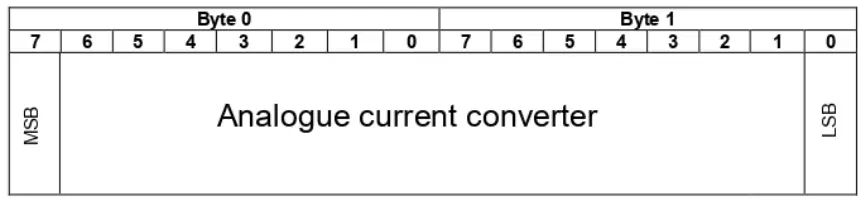
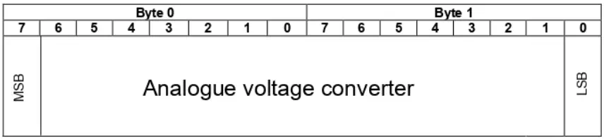
4.2. Process data / input data
FNI IOL-712-000- K023
FNI IOL-714-000- K023
![]() Note
Note
The measuring range from 0 —21.15 mA (for FNI IOL-712-000-K023) will be shown in 16384 steps.
![]() Note
Note
The measuring range from 0 – 10 Volt (for FNI IOL-714-000-K023) will be shown in 16384 steps.
4.3. Parameter data/ Request data
| DPP | SPDU | Object name | Length | Range | Default value | ||
| Index | Index | Sub- Index | |||||
| Identification Data | 0x07 | Vendor ID | 2 Byte | read only | 0x0454 | ||
| 0x08 | |||||||
| 0x09 | Device ID | 3 Byte | 0x099BE2 0x099BE1 |
||||
| 0x0A | |||||||
| 0x0B | |||||||
| 0x10 | 0 | Vendor name | 18 Byte | FAS(Fujian)Co.,LTD | |||
| 0x11 | 0 | Vendor text | 16 Byte | www.fas-elec.com | |||
| 0x12 | 0 | Product name | 19 Byte | FNI IOL-712-000-K023 FNI IOL-714-000-K023 |
|||
| 0x13 | 0 | Product ID | 7 Byte | 0AC021 0AC001 |
|||
| 0x14 | 0 | Product text | 18 Byte | IO-Link 1AI 0…20mA IO-Link 1AI 0…10V |
|||
| 0x16 | 0 | Hardware Revision | 1 Byte | 1.0 | |||
| 0x17 | 0 | Firmware Revision | 23 Byte | 1.0 | |||
| Parameter Data | – | ||||||
4.4. Errors
| Error Code | Additional Code |
| Device application error | Index not available |
| 0x80 | 0x11 |
| Device application error | Subindex not available |
| 0x80 | 0x12 |
| Device application error | Value out of range |
| 0x80 | 0x30 |
4.5. Events
| Class / Qualifier | Code ( high + low) | |||||
| Mode | Type | Instance | ||||
| Appears | Error | AL | Device Hardware | Supply | Supply low voltage | U2 = Supply + 24V |
| 0xC0 | 0x30 | 0x03 | 0x5000 | 0x0100 | 0x0010 | 0x0002 |
| 0xF3 | 0x5112 | |||||
| Disappears | Error | AL | Device Hardware | Supply | Supply low voltage | U2 = Supply + 24V |
| 0x80 | 0x30 | 0x03 | 0x5000 | 0x0100 | 0x0010 | 0x0002 |
| 0xB3 | 0x5112 | |||||
Technical data
5.1. Dimensions

5.2. Mechanical data
| Housing materials | Plastic, Macromelt 6208 |
| IO-Link port | M12, A-coded, male |
| I-port | M12, A-coded, female |
| Enclosure rating per IEC 60529 | IP 67 (only when plugged in and threaded in) |
| Dimensions (W x H x D in mm) | 40 x 50.4 x 14.2 |
| Weight | ca. 50 g |
5.3. Electrical data
| Operating voltage | 18. 30.2 V DC, per EN 61131-2 |
| Ripple | < 1% |
| Current draw without load | <= 30 mA |
| Resolution | 12bit |
| Sampling rate | 3ms |
5.4. Operating conditions
| Operating temperature | -5 °C … 70 °C |
| Storage temperature | -25 C … 70 °C |
5.5. LED indicators

Status LED
FNI IOL-71x-000-K023
| LED | Indicator | Function |
| LED 1 | Green / Green flashing | Communication error / Communication ok |
| LED 2 | Green / Green flashing | Supply sensor & module ok / Undervoltage |
Appendix
6.1. Product ordering code

6.2. Order information
| Order code | Material number | Product ordering code | Label color | Printing IN or OUT |
| 0AC021 | 213978 | FNI IOL-712-000-K023 | Red (RAL5015) | I |
| 0AC001 | 213979 | FNI IOL-714-000-K023 | Blue (RAL3020) | I |
6.3. Scope of delivery
FNI IOL-…-K023 consists of the following components:
- 10-Link module
- User’s guide
![]()
www.fas-elec.com
FAS Electronics
Room 05, Floor 18,
Wangneng Building,Keji East
Road, Shangjie Town, Fuzhou
Tel. +86 591 2278 1506
Fax +86 591 2278 1506
sales@fas-elec.com
” www.fas-elec.com
Nr. 920741-726 E °03,.126846 eEdition G18 eReplaces Edition F18 «Subject to modification.
Documents / Resources
 |
FAS ELECTRONICS IOL-712 IO-Link Analog Adapter [pdf] User Guide IOL-712 IO-Link Analog Adapter, IOL-712, IO-Link Analog Adapter, Analog Adapter, Adapter |