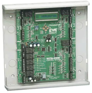
EWC UT3000 Zone Control System
Product Specifications
- Zone Capacity: Control 2 or 3 air zones with 24vac Power Open/Close EWC zone dampers. Twinning two UT3000’s together allows for 4 or 5 zones.
- Compatible HVAC Systems: Communicating HVAC systems based on the ClimateTalkTM communicating open protocol. Also compatible with any 24volt legacy 2 Heat / 1 Cool Gas/Electric system or 2 Heat / 1
Cool conventional or DF Heat Pump. - Compatible Thermostats: Works with Daikin One+ smart thermostat, ComfortNet CTK04 thermostat, typical 24v single stage Heat/Cool thermostat, and typical 2 Heat/1Cool Heat Pump thermostats.
- Automatic Heat / Cool Changeover: Supports automatic changeover thermostat settings for individual zone comfort from the HVAC system..
Frequently Asked Questions (FAQ):
Q: Which thermostats are compatible with the UT3000?
A: The UT3000 is compatible with Daikin One+, ComfortNet CTK04, typical single stage Heat/Cool thermostats, and typical 2 Heat/1Cool Heat Pump thermostats.
Forced Air Zone Controls
The patented UT3000 Zone Control System has been enhanced to provide intelligent zone control of the Daikin FIT™ and ComfortNet™ communicating HVAC systems or 24volt legacy HVAC systems. Create 2 or 3 air zones with a single panel or “twin” two UT3000’s together to create a 4 or 5 zone system. Use EWC 24volt motorized dampers and any off-the-shelf 24volt thermostat or compatible communicating thermostats. Features like Automatic Equipment Recognition, Modulating and Staged BTU capacity control, Dual Fuel functions, Energy Saving features and Precise Control of Supply Air Target & Limit set-points still come standard. Even the LCD display has been enhanced to include easy to read “System Status” messages. EWC Controls raises the bar again and sets another new standard for Residential HVAC Air Zoning.
- Zone Capacity
Control 2 or 3 air zones with 24vac Power Open/Close EWC zone dampers. Twinning two UT3000’s together, allows 4 or 5 zones. - Compatible HVAC Systems
Control Communicating HVAC systems based on the ClimateTalk™ communicating open protocol. Or any 24volt legacy 2 Heat / 1 Cool Gas/Electric system or 2 Heat / 1 Cool conventional or DF Heat Pump. - Compatible Thermostats
The UT3000 is compatible with the Daikin One+ smart thermostat and the ComfortNet CTK04 thermostat. The UT3000 is also compatible with any typical 24v single stage Heat/Cool thermostat and typical 2 Heat/ 1Cool Heat Pump thermostats. - Automatic Heat / Cool Changeover
The UT3000 is compatible with “automatic changeover” thermostat settings, which allows for individual zone comfort from the HVAC system. 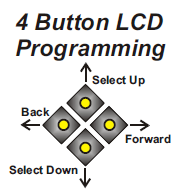 Status LCD System COOL 25%
The Liquid Crystal Display scrolls to show each zone thermostat demand input and the HVAC system demand output. The outside & supply air temperatures are also displayed. In addition, all UT3000 menu programming is performed at the LCD.Four buttons are provided just below the LCD screen. The buttons are used to scroll thru the Menu on the LCD and make your selections. Program the UT3000 and select the features you like. Non-volatile memory maintains your settings even after a long power failure.
System LED’s- In addition to the LCD, a total of 5 colored LED’s provide visual indication of the HVAC system status & mode of operation.
- Damper LED’s
A total of 3 green LED’s labeled Zone 1 thru Zone 3, are also provided to indicate which zone dampers are energized to Open.
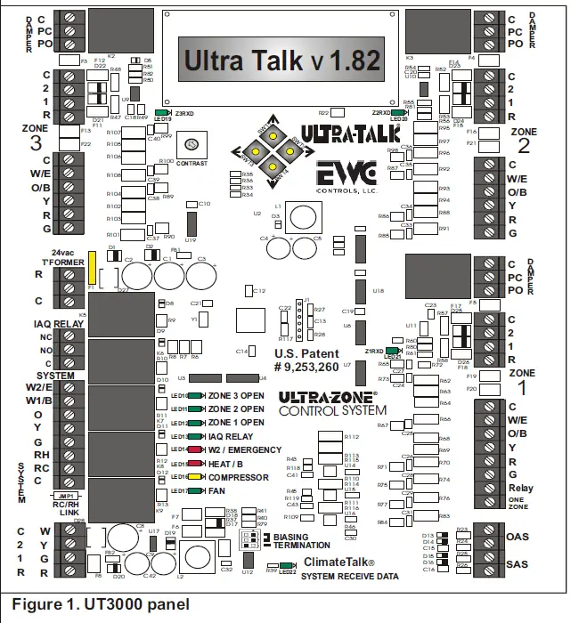
Communicating LED’s
A total of 4 green Pulsing LED’s are provided to indicate a Comm Link has been established with each Communicating T-stat and/or the Communicating HVAC system. A series of Rapid & Random Pulses indicate successful comm-link and data transmission. Otherwise, each Tstat Comm LED will remain Off for non-communicating T-stats.
Fault Free Programming & Intuitive Temperature Control
The UT3000 comes pre-loaded with Default Operating Parameters (See Page 2, Table 1) for Zoned HVAC Systems. The Default Programing means less work for the Installer, but also allows Fine Tuning of the System to Optimize Performance and Personal Preference. The UT3000 operates in Staged and Modulating mode at all times. Multi-Stage and Modulating Equipment will be operated in a manner that maximizes efficiency, maximizes temperature control & improves system performance.
The UT3000 includes a SPDT Indoor Air Quality Dry Relay (IAQ Relay), with a digital & 24v Input Trigger. It can be used to interlock and control Ancillary IAQ functions:
Ancillary IAQ Dry Relay Provided
The UT3000 includes a SPDT Indoor Air Quality Dry Relay (IAQ Relay), with a digital & 24v Input Trigger. It can be used to interlock and control Ancillary IAQ functions:
* Fresh Air Damper * Whole House Humidifier
* Energy Recovery Ventilator
The UT3000 must detect a Fan, Heat or Cool demand from one or more communicating zone thermostats or legacy non-communicating zone thermostats, before the IAQ relay will energize.
INSTALLATION INSTRUCTIONS – See Start-up Guide #090376A0194
- MOUNTING: Choose a suitable location to mount the UT3000 housing. Suitable locations are on the Return Duct, a Nearby Wall or Convenient Studs where plywood can be installed to support the housing. Avoid mounting the UT3000 on the Supply duct. Do not mount the UT3000 directly to any Air-Handler, Furnace, Hot Water Cabinet or Evaporator Cabinet to avoid damaging these devices. Unless code permits, Do not mount the UT3000 in the “open” return air stream. Follow all National and/or Local Mechanical & Building Codes.
- POWER SUPPLY: The UT3000 requires a dedicated 24vac transformer. 40va minimum – 60va maximum. Follow National Electrical Code and/or Local Electrical Code.
WIRING: In most cases standard 18awg solid copper multi-conductor cable works fine. In rare cases 18awg (4 wire) cable may be needed on long outdoor wire runs (= > 100ft) or short wire runs picking up electrical interference. Use two wires for each data circuit, rather than one. Connect the 24vac Power Supply to the - UT3000 and wire-up thermostats and dampers. Use the knock-outs provided on the housing as the wire entry-way. Stripping the cable’s jacket back to the point where the cable enters the housing, reduces bulk and allows easy routing of the individual wires for a professional looking installation.
4 Wire Communicating Network: - Whenever possible, adhere to the Climate Talk™ Color code. RED, GREEN, YELLOW, WHITE. Doing so reduces the possibility of miswiring components.
- PROGRAM: The UT3000 will automatically identify the HVAC system and start running as soon as thermostat demands are detected. Allow 8 – 10 minutes for all Thermostats and the zoned HVAC system to fully configure, depending on the number of zones. The Default Supply air Sensor temperature Targets and off-set
- Limits will be used. You can adjust the menu default settings to the values you prefer.
- When connected to a Conventional 24v HVAC system, scroll thru the LCD menu and select the type of HVAC system you have and the type of thermostats you want to use. Accept the default settings or adjust them as you prefer.
- FINISH: When the Installation is complete, it may be necessary to operate the system in “Test Mode” or “Charging Mode” first! Afterwards, run the system thru it’s paces and observe the HVAC system in all possible modes of operation. Check the Zone Dampers and the Bypass Damper for proper operation. Balance the duct work and adjust the Menu Settings as you prefer.

UT3000 Version 1.82 SPECIFICATIONS and MENU ITEMS
NUMBER OF ZONES: 2 or 3 zones per control panel. 4 or 5 zones by twinning. See Addendum #090376A0180 Rev V.
COMPATIBLE EQUIPMENT
Climate Talk™ based HVAC systems – ComfortNet™& Daikin™ communicating HVAC systems. Up to 4 stages of heat & up to 2 stages of cooling. (Inverter driven AC or HP) (Modulating Gas). Non-Comm. Gas/Electric/Hydronic systems – Up to 2 Stage Heating and 1 Stage Cooling. Non-Comm. Heat Pump or Dual Fuel systems – Up to 2 Stage Heating and 1 Stage Cooling.
COMPATIBLE THERMOSTATS
Climate Talk™based Communicating (Daikin One+ smart thermostat or CTK04ae thermostat. Any 24vac single stage Heat/Cool Thermostat.
Any 24vac 2 Stage Heat, 1 Stage cool Heat Pump Thermostat.
COMPATIBLE DAMPERS
EWC® Ultra-Zone® Models URD, ND, and SID with MA-ND5 or MA-15S motors
Spring Type Dampers (2 or 3 wire) are not compatible due to high current draw.
MAX. DAMPERS PER ZONE:
Up to 3 ND, URD, or SID Dampers Per Zone @ 26mA per damper. Total 9
OVER-CURRENT (Auto-Reset) PROTECTION:
- 2.5Amp main circuit board protection.
- 100mA on each Damper Motor Terminal Block.
- 350mA on each Communicating Thermostat Terminal Block.
- 140mA on each Regular 24v Thermostat and HVAC System Terminal Block.
- UT3000 MAXIMUM CURRENT DRAW = 1.75 Amp.
- POWER REQUIREMENT = 24Vac min.40Va max.60Va 50/60 Hz.
- AMBIENT OPERATING CONDITIONS:
- TEMPERATURE: -4° to 158°F (-20° to 70°C).
- HUMIDITY: 0% – 95% Rh Non-Condensing.
ANCILLARY IAQ DRY RELAY FUNCTIONS
- Control a Whole House Humidifier.
- Interlock an ERV or HRV.
- Interlock a Fresh Air Damper.

ACCESSORIES
Model SAS – Supply Air Sensor (Included/ Required for proportional equipment control). Model OAS – Outdoor Air Sensor (Optional) Unnecessary for communicating outdoor units. Model CPLS – Coil Protection Lockout Switch (Optional/Recommended).
TABLE 1
| FEATURE | DEFAULT | RANGE TO SELECT |
| System Type | Heat/Cool | Heat Pump or Heat/Cool |
| HP Type | NONDual Fuel | Dual Fuel or Non-Dual Fuel |
| T-Stat Type | Heat/Cool | Heat Pump or Heat/Cool |
| Rev Valve | RV ‘O’ | ‘O’ Type RV or ‘B’ Type RV |
| Fan Mode | Gas | GAS or HYDRO (Electric) |
| OAS SP | OFF | OFF or 7° to 42° F |
| O.T. Offset | 8° F | 5° to 20° F |
| U.T. Offset | 7° F | 5° to 12° F |
| SAS HP TGT | 112° F | 90° to 120° F |
| SAS Gas TGT | 142° F | 120° to 170° F |
| SAS Cool TGT | 47° F | 40° to 60° F |
| SAS RSP DLY | 22s | 10seconds – 180seconds |
| W2 Threshold | 95% | 65% – 99% (Adj. in 5 point increments) |
| PURGE FAN | 50% | 25% – 100% (Adj. in 25 point increments) |
| Zone 1 Weight | 70% | 0% to 100% |
| Zone 2 Weight | 15% | 0% to 100% |
| Zone 3 Weight | 15% | 0% to 100% |
| Total Zones | 3 | 2 or 3 zones per panel |
| Limit SAS PID | N | Yes or No |
| DMP DFLT | Open | Open or Close |
| W2 lockout | 99° F | 5°F to 99°F |
LCD Screen Programming
Remember, if you are installing a Communicating HVAC system, this programming is done for you! There is no need to perform the Programming steps below. You can still program certain detail functions ie. (24v T-stat Type). Select only the functions you want or need. Your changes will take effect in real time and the UT3000 will remember your settings even after a power failure. When the power is restored, the UT3000 will re-configure the network automatically.

Use the Forward & Back buttons to navigate thru the Menu Features. Use the Up & Down buttons to change or adjust the options available in that feature. Place a check mark next to each selection in the box for future reference!
- Select either Heat Pump or regular Heat/Cool system. If you have a Heat Pump and a Gas/Oil Furnace, you should still select Heat Pump.

- If you selected a Heat Pump system in Step 1, select whether your Heat Pump has a Furnace back-up system or Electric Heat back-up. You can still operate any Heat Pump in a restricted mode by using the OAS-SP feature.

- Select the type of 24v (Non-Communicating) thermostat you want to use.You may have a Communicating thermostat in Zone 1 and Regular 24v thermostats in the other zones.
So you must select which type are in the other zones. - You cannot mix non-communicating HP and HC type thermostats. All 24v T-stats must be Wired and/or Programmed for HC or HP Operation. Conflicting Zone Demands due to mis-wiring or incorrect programming will not be recognized!

- If you selected Heat Pump Thermostats in Step 3, then select the type of Reversing Valve Operation.

- Select how you want the Indoor Fan to operate during Heating Operations. Select HYDRO if you have an Air-Handler with Hot Water Coil or an Electric Furnace. Select GAS if your system is a Gas/Oil Furnace with A/C.
If you have communicating equipment, this feature is set for you automatically 
- If you are using the Outside Air Data to Lock-Out the Heat Pump, select that Set-Point Temperature right here. If you do not want to use Outside Air Data to lock-out the heat Pump, adjust the OAS SP (Set-Point) value down to the OFF position.

- If the Supply Air Temperature exceeds any Target Set-Point, (Plus or Minus the Off-Set), the resulting value becomes the Over Temperature Condition. Choose an Off-Set value that will provide a safe operating limit for your HVAC equipment. The UT3000 will cycle the system off-line for 3 minutes, allowing the discharge air temperature to moderate while displaying the Over or Under Temp Condition (OTC or UTC) screen, depending on the mode of operation.


The UT3000 wants to match the Actual Supply Air temperature to the Cool or Heat Target Set-point. The SAS Response Delay determines how fast the UT3000 will ramp the HVAC system. Via the UT3000’s advanced staging logic, (see the next pages) the UT3000 will ramp (add points) to the System output demand (increasing BTU capacity) in an effort to match the Actual Supply Air temperature to the Cool or Heat Target Set-point. Ramping will stop if the point adding process triples the sum of the zone weight multiplied by the zone demand, regardless of the supply air temperature.
Use the Forward & Back buttons to navigate thru the Menu Features. Use the Up & Down buttons to change or adjust the options available in that feature. Place a check mark next to each selection or write the value in the box for future reference!
- Select the desired HP Heating Supply Air Sensor Temperature Target that the UT3000 will demand from the HVAC system. The UT3000 will automatically stage the HVAC system Up or Down to maintain this value.
- Select the desired GAS Heating Supply Air Sensor Temperature Target that the UT3000 will demand from the HVAC system. The UT3000 will automatically stage the HVAC system Up or Down to maintain this value.
- Select the desired COOLING Supply Air Sensor Temperature Target that the UT3000 will demand from the HVAC system. The UT3000 will automatically stage the HVAC system Up or Down to maintain this value.
- Select how fast the UT3000 will “Add Points” to achieve the calculated “HVAC system” BTU capacity level. The screen above specifies that the UT3000 will add one point (to the active system demand ) every 22seconds. This determines how fast the UT3000 will increase the BTU output of the HVAC system.
- The point adding process starts after the UT3000 calculates the sum of one or more zone weight values, multiplied by the observed demand value from each active zone thermostat.
- Points are also added if the PID loop is enabled. Note: The PID loop is enabled by default. The PID Loop is allowed to boost (triple) the sum of one or more zone weight values, multiplied by each active zone thermostat’s (momentary) demand value.
- Note: The point adding process will stop, if the UT3000 detects a condition where the actual supply air temperature matches the “active” target set-point (+ – 1°F). (Cool Target, Gas Target or HP Target).
- Example: The UT3000 will stop adding points if the actual supply air temperature is 49°F, 50°F or 51°F, and the Cool Target has been set to 50°F. Continued on the next column.

- COOL MODE: If the Cooling Supply Air Temperature is above the Cooling Target (> 1°F), the UT3000 will increase the SYS Cool output by 1 point every 22 seconds. If the Cooling Supply Air Temperature is below the Cooling Target (< 1°F), the UT3000 will decrease the SYS Cool output by 2 points every 22 seconds.
- HEAT MODE: If the Heating Supply Air Temperature is below the Heating Target (< 1°F), the UT3000 will increase the SYS Heat output by 1 point every 22 seconds. If the Heating Supply Air Temperature is above the Heating Target (> 1°F), the UT3000 will decrease the SYS Heat output by 2 points every 22 seconds.
- No points will be added if the actual supply air temperature matches the “active” supply air temperature target (+ – 1°F). The point adding/deducting process will stop under this condition.

- Select the value at which the Auxiliary (W2) or Back-up system energizes. The Range is 65% – 99% and the default value is 95% of System (SYS) Output. Setting the value low means the Auxiliary system will operate more often. Setting a high value means the Auxiliary system operates less often. There is a 5% differential added to the value selected which prevents short cycling. Setting the W2 threshold to 99% effectively turns it OFF. The reason for this is the differential. So, a value of 94% actually trips at 99%. Thus, a value of 99% would require the System Output to reach 104% which is impossible. Set the W2 Threshold to 99%, if you want the Auxiliary system to energize on the Outside Air set-point (OAS SP) only! If desired, you can use the Outside Air Set-point and set the W2 Threshold to maximum 95%. That would require the System (SYS) Output Percentage to reach 100% demand or the Outside Air temperature drop low enough, to energize Auxiliary heat.

- Select how fast you want the Indoor Fan to run at the end of a cycle, to Purge the last of the hot or cool air into the last zone calling. You may select 25%, 50%, 75% or 100%.The default value is 50%. Note 1: Typically, the HVAC system’s own purge function (speed and duration) supercedes the zone system’s purge function. Note 2: Fan Only speed demands from communicating T-stats can be changed by the end user (Low, Medium or High). Fan Only speed demands from Non-communicating T-stats are interpreted as High. Note 3: Fan Only speed demands are multiplied by that zone’s assigned weight value before being sent on to the HVAC system. Important Note: Review all Programming Features carefully and call EWC Controls if you have questions. With years of experience Zoning HVAC systems, we have plugged in default values that should work fine for the majority of the jobs you will encounter. If desired, you can adjust the settings to your own preference. When doing so, wait patiently and observe the effect of those changes before changing them again. The UT3000’s SYS output (PI Control) to the HVAC equipment will vary depending on factors such as the Internal & External Load, SAS Response Delay Setting, Supply Air Target set-point, Thermostat type and the Thermostat demand value.
The UT3000 utilizes a zone weighting feature. You can select the weight for each zone independently. For example, if zone 1 has more heat loss/gain than zone 2 or zone 3, you can now assign it more weight. Three zone default weight values are 70/15/15. Two zone default weight values are 60/40.
- Select the Weight value that will be applied to Zone 1 Thermostat. You may select from a range of 0% to 100%. The factory default value is 70%. The sum of all the zones weights can add up to 100% or less.
- Select the Weight value that will be applied to Zone 2 Thermostat. You may select from a range of 0% to 100%. The factory default value is 15%. The sum of all the zones weights can add up to 100% or less.
- Select the Weight value that will be applied to Zone 3 Thermostat. You may select from a range of 0% to 100%. The factory default value is 15%. The sum of all the zones weights can add up to 100% or less.
- Select the total number of zones (thermostats) you have connected to each UT3000. You may select 2 zones or 3 zones. The factory default value is 3 zones. It may be necessary to assign very low weight values to some or all zones zones, in order to avoid air noise issues. The total assigned weight values do not have to equal 100%, but going above 100% is not permitted.

- Select “N” for NO, if you want the UT3000 to boost the BTU capacity of the HVAC system, above the active zone(s) calculated demand. See page 16. The PID Loop is allowed to boost (triple) the sum of one or more zone weight values, multiplied by the observed demand value of each active zone. The UT3000 System (SYS) demand output value, is based on the sum of one or more zone assigned weight values, multiplied by the observed demand values of each active zone. This is the recommended setting for Daikin communicating Inverter AC/HP & gas Modulating systems. Note: The PID boost process (point adding) can be interrupted. See page 4, Step 11.

- Select “Y” for YES, if you do not want the UT3000 to boost the BTU capacity of the HVAC system, above the active zone(s) calculated demand. See page 17. This will limit the UT3000 System (SYS) demand output value, to the base sum of one or more zone weight values, multiplied by the observed demand value of each active zone. Basically, the UT3000 will not boost (triple) the sum of the zone demands. This is the recommended setting for communicating two stage systems.
 Change the default position of the zone dampers when the HVAC system is idle. The factory default is to “OPEN” all zone dampers when idle. Select “CLOSE” if desired and make sure the HVAC system’s purge cycle is set for no longer than 90 seconds. Setting “CLOSE” on a sub-panel will only apply to the zone dampers connected to that specific sub-panel.
- W2 Lockout feature allows the installer to prevent Auxiliary Heat from energizing above a selected outside temperature. An energy saving code requirement in some states.

- The final program screen displays the code version of your UT3000. It may be different than shown above. No further action is required. Leave the buttons alone for 10 seconds and the LCD screen will resume scrolling. The programming is complete and the UT3000 will store all settings into permanent memory.

LCD System Messages
Once the programming is complete and the System is running, the LCD screen will scroll and display the following data screens continuously. The HVAC system mode of operation is displayed including Supply Air and Outdoor Air temperature, Auxiliary and Emergency mode including IAQ Functions. The UT3000 LCD will continuously Scroll data as to which Zones are actively calling for a Heating, Cooling or Fan Operation. By watching the LCD display you can observe all system functions as they occur. If desired, you can lock the LCD on a single screen by pushing the Program Up button one time. Then select the screen you want to watch using the Up or Down button. The LCD will stay locked on that screen for 10 minutes then resume scrolling, or you can unlock the screen by pushing the Forward button one time. Below are typical LCD data screen examples:
- This screen is displayed when there are no demands from any zones.
- Communicating Thermostats are capable of providing a proportional heat or cool demand signal.
- Zone 1 is calling for Heat @30%. This indicates the presence of a Communicating Thermostat in Zone 1 whose demands are given a weighted value due to it’s proportional capability. (0% – 30% – 60% – 85% – 100% – etc.)
- 24v HP Thermostats cannot provide a proportional heat or cool demand signal. ie:Heat demand = 50% -100% (Y with Aux) Cool demand = 100% (Y alone)
Zone 2 is calling for Heat @50%. This indicates the presence of a Regular 24v HP T-stat (Calling for 1st stage heat) in Zone 2. - 24v HC Thermostats cannot provide a proportional heat or cool demand signal. Heat demand = 100% (W) Cool demand = 100% (Y)

Zone 3 is calling for Cooling @100%. This indicates the presence of a Regular 24v H/C Thermostat in Zone 3.
IMPORTANT NOTE: You cannot mix 24V HP Thermostats with 24V Heat/Cool Thermostats. A Typical installation may have a Communicating T-stat in Zone 1 and the rest may be 24v Legacy type.
Acceptable UT3000 Thermostat Combinations
- Zone 1 = Communicating
- Zone 2 = Communicating
- Zone 3 = Communicating
- Zone 1 = Communicating NOTE: The Comm T-stat should be in Zone 1.
- Zone 2 = 24v H/C
- Zone 3 = 24v H/C
- Zone 1 = Communicating NOTE: The Comm T-stat should be in Zone 1.
- Zone 2 = 24v HP
- Zone 3 = 24v HP
- Zone 1 = 24v H/C
- Zone 2 = 24v H/C
- Zone 3 = 24v H/C
- Zone 1 = 24v HP
- Zone 2 = 24v HP Refer to Page 14 for Sample Thermostat Diagrams
- Zone 3 = 24v HP
 This screen displays the SYSTEM (SYS) Output percentage to the HVAC Equipment. In this Heat Pump Example, the UT3000 is demanding 35% heating capacity and 15% fan capacity. That means 1st stage heat (Y1) is active. If the HP Target set-point is not satisfied before reaching 51% SYS Output, Y2 will energize. If the HP target set-point is still not satisfied before reaching the W2 threshold value, W2 will energize.
- 01% – 50% Output = Y1HP or Y1A/C or W1Gas
- 51% – 65% Output = Y2HP or Y2A/C or W2Gas
- W2 Threshold 65% – 95% = W2HP
Note: The UT3000 may interpret a Zone Thermostat input as 100% demand but it may not Output a 100% System Demand. The UT3000 will demand only as much System Capacity as is necessary, to satisfy the Active Supply Air Target Set- Point or, it stops staging due to the zone weighting system.
This screen displays the System Percentage demand from the Auxiliary and/or the Emergency system. The Aux will display a value during Auxiliary mode. Both screens will display values during Emergency mode. The next screen displays the System Percentage demand to Humidify or De-humidify. Humidify/IAQ demands may come from a Communicating thermostat or a 24v device like a conventional Humidistat. The UT3000 honors De-Humidify demands from Communicating thermostats only. The Dehumidify function is the AC system (cool mode) with low speed fan. 
This screen is displayed at the end of a heating or cooling call. The damper(s) in the last zone to satisfy are held open while others remain closed, allowing the purge function. The purge cycle is fixed at 210 seconds. 
NEW LCD System Messages

This screen displays the SYSTEM (SYS) Output percentage to the HVAC Equipment. In this example, the UT3000 is demanding 75% cooling capacity. That means 2nd stage cool (Y2) is active, or the outdoor Inverter is operating at 75% BTU cooling capacity.
NOTE: During Cooling & Heating operations, delivered CFM is controlled by the HVAC system! The only time the indoor fan operates at the UT3000’s demand is during Fan Only. 
- This screen shows the duct temperature at the location of the supply air sensor in real time. The UT3000 monitors and compares the Actual Supply Air Temperature to the selected HP Target, Cooling Target or Gas Target Set-points.
- If the Supply Air Sensor is disconnected or fails, the UT3000 will display the “Bad Sensor” screen and will default to “Timed Mode” staging until the Zone T-stat demands are satisfied.
- If the UT3000 observes the supply air temperature exceed any Target set-point plus or minus the OT or UT off-set value, the UT3000 will display the screens shown below.

- This screen shows the outside air temperature in real time, at the location of the outside air sensor. This OA value could be from the Communicating outdoor unit or from a sensor (#OAS) connected to the UT3000.
- If the OAS sensor fails or is disconnected, the UT3000 will display the “Bad Sensor” screen and will default to emergency mode or high heat for all heating demands.
- NOTE: The !OAS Sensor Bad! screen is also a reliable indication that the UT3000 is not communicating with the outdoor HP or AC unit! Review the troubleshooting chart for corrective action.

- This screen displays the SYSTEM (SYS) Output percentage to the HVAC Equipment. In this example, the UT3000 is demanding 30% Fan Only capacity.
- NOTE: The only time the indoor fan operates at the UT3000’s demand is during Fan Only functions. During Cooling & Heating operations, delivered CFM is controlled by the HVAC system!

- The Zone 1 & Zone 2 screens above (left) each show heating demands of 50% and 100% respectively.
- The Zone 3 screen above (right) shows a cooling demand of 30%. All calls are active at the same time but the Zone 1 & Zone 2 heating calls were detected first, so the UT3000 honored Zone 1 & Zone 2 by running the heating system and closing the Zone 3 damper.
- The UT3000 will delay (postpone) the Zone 3 cooling demand until Zone 1 & 2 satisfy OR the 20 minute
“Opposite Mode” clock expires. - The 20 minute “Opposite Mode” clock has now expired because both heating demands did not satisfy during the allotted 20 minutes. Zone 1 and/or Zone 2 heating demands may still be present, but the UT3000 will now service the cool demand in Zone 3, and restart the 20 minute “Opposite Mode” clock again.
- The UT3000 will display one of the screens above, depending on whether the change-over is from Heat to Cool (HC) or from Cool to Heat (CH). The display is your indication that “Opposing Demands” from the zone thermostats are occurring.

TIMER DEFINITIONS

The Diagrams shown below reflect different ways to utilize the IAQ Dry Relay to your advantage. Other wiring is not shown for clarity.
The communicating thermostat can send a digital signal to humidify, but the wiring method shown above is now preferred (best practice) and works consistently! You must have at least one spare wire!
Powered (Steam) Humidifiers just need a dry contact to start. Connect the H & H humidifier terminals to “C” and “NO” at the IAQ relay terminal block as shown above. Refer to Wiring diagram 090512A0519-A if your humidifier is not self-powered or call EWC Tech Support.
It is advised to use Zone 1 as the “only” humidifier control. However, other zone thermostats can be wired in the same manner resulting in two or three wires connected to the “relay” terminal.
- Access the thermostat’s advanced menu (Dealer Edit)
- “Add” the humidifier to the Equipment Folder of the thermostat.
- Select “On with Heat” or “On with Heat and Hum”.
- Select Fan speed at 75% to 100% in order to move sufficient airflow to properly humidify.

NOTE: If the IAQ relay is used for fresh air, it cannot be used for humidifier control.  NOTE: If the IAQ relay is used for fresh air, it cannot be used for humidifier control.
UT3000 Features at a Glance

2 – 3 Zones Fully Communicating Application

WIRING INSTRUCTIONS
WARNING: THESE PANELS ARE DESIGNED FOR USE WITH 24VAC. DO NOT USE OTHER VOLTAGES! USE CAUTION TO AVOID ELECTRIC SHOCK OR EQUIPMENT DAMAGE. ALL WORK SHOULD BE PERFORMED TO LOCAL AND NATIONAL CODES AND ORDINANCES. USE 18 AWG SOLID COPPER, COLOR-CODED, MULTI-CONDUCTOR THERMOSTAT CABLE.
Thermostat Wiring
EWC highly recommends using Daikin ONE communicating thermostats in all zones! Enhanced de-humidification (via the FIT HVAC system) cannot be achieved without a communicating thermostat. Communication LEDs (LED19, 20, 21 & 22) are provided at each “communicating terminal block” to indicate that a “link” has been established with each communicating network. (Z1, Z2, Z3 & SYSTEM). Each Comm LED will pulse (at random intervals) to indicate the “link” is active. Otherwise, the Comm LED will blink slowly to indicate “no network detected”. The Comm LED will remain OFF (by zone) when non-communicating thermostats have been detected. Be patient and allow sufficient time (10 – 15 minutes) for the UT3000 to discover the HVAC network, and for all communicating thermostats to finish their configuration process, which includes equipment identification, menus and outside temperature conditions. Ideally, all zone thermostats should be set to OFF during this process.
Figure 2a
For a detailed commissioning and installation video, including further instructions on the Daikin One+ smart thermostat, please visit the thermostat website at https://daikinone/smart_thermostats/oneplus/pros/
Figure 2c
Typical thermostat wired and programmed for 1 heat & 1 cool. Refer to Mfr’s instructions.
Figure 2b
Typical Heat Pump Thermostat configured for 2 heat & 1 cool. Refer to Mfr’s instructions.
Figure 2d
WiFi thermostat configured for 1 heat & 1 cool. Refer to Mfr’s instructions. Nest or Ecobee brand Thermostats are also compatible.
NOTE: The UT3000 allows the user to install Communicating Thermostats in all zones! EWC highly recommends using communicating thermostats in all zones! System commissioning & maintenance functions are accessed via the zone 1 communicating thermostat only! Enhanced de-humidification is achieved via the communicating thermostats. The Daikin One+ thermostat MUST be connected to Zone 1 for “Daikin Cloud Inverter Menu” access. Communicating thermostats can be used in combination with 24v non-communicating thermostats if desired.
NOTE: Regardless of the type of thermostats used, the W2 Threshold feature, W2 Lockout feature and/or the OAS Set-Point feature, will control the Auxiliary/Backup heat in non-emergency mode. Once the W2 Threshold is crossed, the W2 Lockout set-point is reached or the Outdoor Air Set-Point is reached, Auxiliary Heat will energize. Auxiliary demands from each thermostat simply increase the observed (input) demand from that zone, which may or may not activate Auxiliary heat operations, based on the use and settings of the above mentioned features.
NOTE: High fire (W2) on a 2 stage communicating furnace occurs at 51% system demand, similar to Y2 HP Heating or Cooling. The W2 Threshold setting has no affect on a 2 stage or modulating furnace. The W2 Threshold setting only affects Auxiliary/Backup on heat pump systems.
Daikin Communicating Inverter System “FIT”

Contact EWC Controls Technical Support for assistance on these and other Equipment Wiring Solutions.
System Wiring
The UT3000 panel was designed to be Plug and Play! We have provided several typical field wiring diagrams for your reference. Your actual field wiring may vary but in most cases will match these diagrams. In full communicating mode, four wires are all that is required from each thermostat and to the HVAC system. The UT3000 will “Talk” to the HVAC system and “Talk” to the thermostats in order to automatically setup and start operating the HVAC system. Your new communicating heat pump may have a non-communicating backup/auxiliary system, or your new communicating furnace still uses the non-communicating condensing unit outside. In all of these cases, the UT3000 is compatible. Other non-communicating application wiring diagrams and solutions are available. Contact EWC Controls Technical Support for .
“Daikin or ComfortNet” communicating 2 Stage Heat Pump or A/C System
Four wires are required to each component. Plug & Play 
“Daikin or ComfortNet” communicating INVERTER Heat Pump or A/C system
Two or four wires are required to each component. Plug & Play 
Existing Boiler with New HP System
You may have a new Communicating Heat Pump but want to use your Boiler (Hot Water Coil) as the Auxiliary backup rather than electric resistance heat. Connect the T&T circuit from your boiler control panel to a field relay installed in the Air handler. Wire as shown.
Note: You must specify the KW electric heat rating (HW coil BTU equivalent) in the Air Handler’s “ClimateTalk User Menu” (or Dip Switch settings) to achieve the correct/desired airflow! 
Communicating Furnace with 24v Legacy Air Conditioner
Four wires are required from the UT3000 to the Communicating furnace. Two wires are required to the 24v air conditioner.
Note: You must specify the tonnage of the non-communicating outdoor unit, inside the Furnace equipment User Menu, in order to achieve the correct airflow! 
DAMPER WIRING
- Note: The 100mA Damper Auto-Reset Circuit Breaker (protecting each zone damper output) may trip, if too many dampers are connected to a single zone! In particular if the UT3000 is located in a hot attic.
- You can connect up to three (3) Model ND, URD, or SID type dampers to a single terminal block without tripping the breaker, regardless of the ambient temperature.
- Note: You can select all zone dampers to default
- “OPEN” or “CLOSE” during IDLE periods.
Idle periods are defined as
- The HVAC system is idle and not running.
- Caution: Inverter based “Oil Return “mode runs without a zone thermostat demand!
- All Fan/Purge functions have timed out.
- All zone thermostat demands are satisfied.
- No zone thermostat demands are detected. Zone thermostat demands are defined as:
- Heating
- Cooling
- Fan Only / Circulate
- Humidification / De-humidification

PARALLEL versus SERIES wiring Resist the urge to wire damper motors in series, jumping from motor to motor to motor. Wiring multiple motors in parallel (as shown below in Figures 5b and 5c) reduces the possibility of loose connections, high resistance and voltage drop.
On these dampers and most older style dampers, always wire up number to number or by terminal designations.
PAY ATTENTION TO YOUR WIRING!
(C to Com)(PO to PO)(PC to PC) (C=1) (PO=4) (PC=6) 

ZONE WEIGHTING FEATURE
The HVAC system’s momentary BTU capacity level, is determined by multiplying one or more zone weight assignment values by the proportional (or fixed) thermostat demand value, coming from each respective zone. If the PID loop is active, the UT3000 will “boost” the HVAC system’s BTU capacity above the base sum of zone weight(s) multiplied by zone demand(s). 
The HVAC system’s momentary BTU capacity level, is determined by multiplying one or more zone weight assignment values by the proportional (or fixed) thermostat demand value, coming from each respective zone. If the PID loop is inactive, the UT3000 will not “boost” the HVAC system’s BTU capacity above the base sum of zone weight(s) multiplied by zone demand(s). 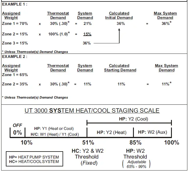
TROUBLESHOOTING
| SYMPTOM
Cooling will not run at all. Zone thermostat displays E11 fault code. LCD & LED’s are responding properly. |
SOLUTIONS
Some HVAC systems require a “System Test” prior to normal operation. Access the Zone 1 thermostat and perform the System Startup Test. Clear all fault codes in the Outdoor and Indoor unit diagnostic menu folders. Access the Zone 1 thermostat and initiate System Charge mode. |
|||
| HVAC system does not always respond properly. Periodic faults are displayed on thermostats. Cannot achieve 0.6vdc BIAS on the system data wires. | Check BIAS DC voltages: Data 1 to C = 2.8 & Data 2 to C = 2.2 or Data 1 to C = 1.9 & Data 2 to C = 1.3 Combination of CAPE coil and 2 stage furnace will read Data 1 to C = 2.3 & Data 2 to C = 1. BIAS dip switches (#1 & #2) at the bottom of the UT3000, should be set to ON. Clear all fault codes in the Outdoor and Indoor unit diagnostic menu folders. | |||
| Check damper motor wiring for proper connections. Too many or (incompatible) dampers connected to a single zone. Check damper motor 24volt output. Test wires for Continuity/Shorts. Check damper motor wiring for shorts/miswiring.
Refer to Page 15 of the Technical Bulletin for Damper Wiring. |
||||
| LCD & LED’s function and HVAC system functions normally but dampers do not respond. | ||||
| LCD & LED’s do not function and | Check HVAC & UT3000 system transformer supply voltage. | |||
| HVAC system does not respond. | Check HVAC & UT3000 system 24vac transformer voltage/fuse/breakers.
Test all wires for Continuity, shorts to 24v Common or shorts to earth ground. |
|||
| Time Delay is Active and won’t allow Heat |
Back |
Forward |
Check HVAC & UT3000 system wiring for shorts and miswiring. | |
| When Troubleshooting, Simultaneously Press the Back & Forward buttons for 1 | ||||
| or Cool to Function. | second to Bypass any Active Time Delay. | |||
CHECK YOUR WIRING
| DETECTING 24vac SHORTS | SYMPTOM: Entire Panel or a Single Zone appears to be dead! |
| HVAC system not responding and UT3000 LED’s are off. | If 24vac short has occurred, 24vac will be present at the UT3000 24v Input terminals R & C, but 24vac will not be present at any thermostat R&C terminals. |
| One or more thermostats will not power up and/or show a display. | SOLUTIONS: Remove wires from thermostat terminal blocks and allow 140 or 350mA circuit breaker to cool! Find and repair short(s) in thermostat field wiring. Restore 24 vac power. |
| ISOLATING 24vac SHORTS
140mA, 350mA & 100mA circuit breakers protect the UT3000 and react to a short in the Thermostat or Damper Motor field wiring. |
SOLUTIONS: Disconnect the wire(s) from the ‘R’ terminals on the UT3000 thermostat terminal blocks , and the “C/PO/PC’’ terminals on the UT3000 damper motor terminal blocks. Restore power. If the short is no longer present, Ohm out the thermostat and damper field wiring for continuity, shorts to common and/or shorts to earth ground. Replace or repair wires as necessary. Restore power. |
Detecting 24v shorts to common or shorts to earth ground
When the 2.5A (F1)breaker is tripped it will get hot to the touch! The LCD and the LED’s will not illuminate!
To reset the breaker, locate the short by removing each hot wire connected to the panel, one at a time. When the shorted wire is removed, the panel will resume normal functions. Now you must repair or replace the shorted wire. If one or more 140mA, 350mA or 100mA breakers trip, only the device(s) connected to that block will be affected. Remove each hot wire connected to that block until the voltage is restored. Find and repair the shorted wires or device before re-connecting the wires. If there is a short between the Data 1 & 2 wires or if the Data wires are shorted to 24v or earth ground, the communicating thermostat on that zone will alert you by displaying “Call for Service”. If a non- communicating thermostat is connected and a short occurs on the 24v wires, the thermostat will not power up and that zone will not function. Find and repair the short using the methods described above.
TECHNICAL SUPPORT
EWC Controls provides superior toll free Troubleshooting Support for the UT3000 when you are on the job site!
Call 1-800-446-3110 Monday – Friday 8am to 5pm EST. Otherwise call 1-732-446-3110 for information on the UT3000 and other ULTRA-ZONE® products. Visit our web site to download this Technical Bulletin and other related information at www.ewccontrols.com
When calling for Technical Support from the job-site, please have a good quality multi-meter, pocket screwdriver, and wire cutters/strippers on hand.
JOB NOTES:
For an easy start-up using the UT3000 to commission the HVAC system, see Start-Up & Commission guide #090376A0194.
This Technical Bulletin and Addendum sheet are available for download at www.ewccontrols.com
For installation guidance and wiring diagrams on “twinning” applications ( 4 and 5 zone) systems, see Addendum sheet #090376A0180 Rev V.
P/N 090375A0280 REV. A Copyright © July 10, 2024 EWC Controls, LLC ALL Rights Reserved www.ewccontrols.com
If you have questions pertaining to this product, contact EWC Technical Support at 800-446-3110. You can also Email us at tech@ewccontrols.com
EWC Controls provides superior toll free Troubleshooting Support for the UT3000 when you are on the job site!
Call 1-800-446-3110 Monday – Friday 8am to 5pm EST. Otherwise call 1-732-446-3110 for information on the UT3000 and other ULTRA-ZONE® products. Visit our web site to download this Technical Bulletin and other related information at www.ewccontrols.com
When calling for Technical Support from the job-site, please have a good quality multi-meter, pocket screwdriver, and wire cutters/strippers on hand.
This Technical Bulletin and Addendum sheet are available in Spanish. Download #090375A0249 rev E and #090376A0188 rev C at www.ewccontrols.com
Documents / Resources
 |
EWC UT3000 Zone Control System [pdf] User Manual UT3000 Zone Control System, UT3000, Zone Control System, Control System, System |


