![]()
 User’s Manual
RFID-PBA1
Ver. 1.00
Copyright © 2025 by EVERINT, all rights reserved.
Overview
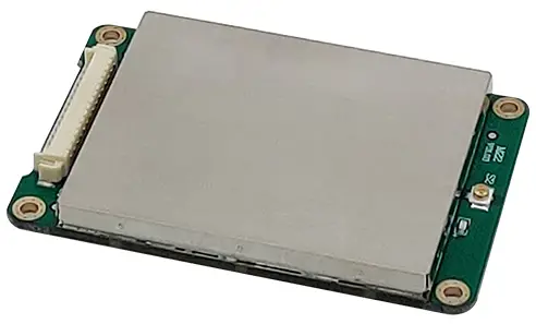
RFID-PBA1 is a UHF RFID module that uses 900MHz radio frequency.
Composition
 Module Pin Details
| Pin No | Pin name | Description |
| 1 | VCC | DC Power |
| 2 | GND | Ground |
| 3 | NC | Not Connection |
| 4 | NC | Not Connection |
| 5 | NC | Not Connection |
| 6 | NC | Not Connection |
| 7 | ISP_MODEb | Mode settings |
| 8 | CSE | Chip select enable |
| 9 | NC | Not Connection |
| 10 | NC | Not Connection |
| 11 | NC | Not Connection |
| 12 | NC | Not Connection |
| 13 | NC | Not Connection |
| 14 | NC | Not Connection |
| 15 | GND | Ground |
| 16 | GND | Ground |
| 17 | GND | Ground |
| 18 | RF IO | Rx Input / Tx Output |
| 19 | GND | Ground |
| 20 | VCC | DC Power |
| 21 | VCC | DC Power |
| 22 | GND | Ground |
| 23 | GND | Ground |
| 24 | GND | Ground |
| 25 | GND | Ground |
| 26 | GND | Ground |
| 27 | GND | Ground |
| 28 | NC | Not Connection |
| 29 | NC | Not Connection |
| 30 | NC | Not Connection |
| 31 | NC | Not Connection |
| 32 | NC | Not Connection |
| 33 | NC | Not Connection |
| 34 | TXD0 | UART Output |
| 35 | RXD0 | UART Input |
Operation Description
 ANT1 Info
– Model part No.: U.FL-R-SMT-1
– Connector type: Coaxial Micro-Receptacle
– Manufacturer: HIROSE
3-1 Power Supply
3.3V DC power is supply to the VCC (Pin1, 20, 21).
3-2 Interface
The serial interface is assigned with two pins. RXD0 assigned to Pin35 is the pin for receiving commands from the host, and TXD0 assigned to Pin34 is the pin for transmitting responses from the host. Pin connection is shown as below figure. 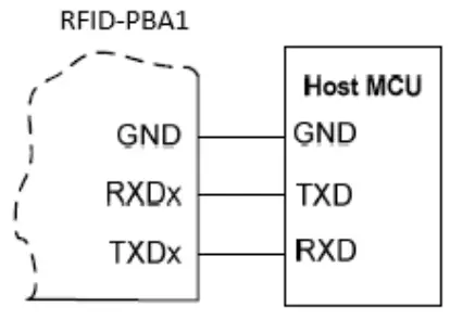 3-3 RF IO
The RF I/O assigned to Pin18 is optimized at 50ohm impedance.
3-4 CSE (Chip select enable)
CSE assigned to Pin8 is ‘1’: Operation / ‘0’: Not Operation
3-5 Mode settings
ISP_MODEb assigned to Pin7 is set to logic ‘1’. (Use pull-up resistor)
Specifications
| No. | Item | Unit | Specification | ||
| Min | Typ. | Max | |||
| 1 | Frequency Range | MHz | 903. | 927. | |
| 2 | Operating Temperature | °C | -20 | 70 | |
| 3 | Operating Humidity | % | 0 | 90 | |
| 4 | DC Power | V | 3. | 4. | |
| 5 | Host Interface | UART (Tx, Rx) | |||
| 6 | RF Output | dBm | 23 | ||
| 7 | RF 10 Impedance | ohm | 50 | ||
- FCC ID: 2AKMF-RFID-PBA1
- IC: 22266- RFID-PBA1
FCC Statement
This device complies with Part 15 of the FCC Rules. Operation is subject to the following two conditions:
- This device may not cause harmful interference.
- This device must accept any interference received, including interference that may cause undesired operation.
Caution
- Any changes or modifications not expressly approved by the party responsible for compliance could void the user’s authority to operate the equipment.
- A minimum separation distance of 20 cm must be maintained between the antenna and any person to satisfy RF exposure requirements.
Radio Frequency Interference
This device generates, uses, and can radiate radio frequency energy. If not installed and used in accordance with the instructions, it may cause harmful interference to radio communications. There is no guarantee that interference will not occur in a particular installation. If this equipment does cause harmful interference to radio or television reception, the user is encouraged to try to correct the interference by one or more of the following measures:
- Reorient or relocate the receiving antenna.
- Increase the separation between the equipment and receiver.
- Connect the equipment into an outlet on a circuit different from that to which the receiver is connected.
- Consult the dealer or an experienced radio/TV technician for help.
OEM Integration Requirements
General Conditions
This device is intended only for OEM integrators under the following conditions:
- The module must be installed such that a minimum separation distance of 20 cm is maintained between the radiator (antenna) and all persons.
- The module is limited to installation in mobile or fixed applications.
- The transmitter module must not be co-located or operating in conjunction with any other antenna or transmitter, except in accordance with FCC multi-transmitter product procedures.
- The module must only be used with the included onboard antenna or antennas approved by the manufacturer (EVERINT CO., LTD.). Use of unauthorized antennas is strictly prohibited.
- Ensure that the power supply to the module is clean, regulated 3.3V DC.
- Use appropriate decoupling capacitors near the VCC pins to minimize noise.
Installation and End-User Manual
- The OEM integrator is responsible for ensuring that the end-user manual does not contain instructions on how to install or remove the RF module.
- The OEM integrator must include the required FCC statements (per Part 15.19 and 15.21) in the user manual of the host device.
- The user manual for the host product must clearly indicate the operating requirements and conditions to ensure compliance with current FCC RF exposure guidelines.
Labeling Requirements
Module Labeling
The module is labeled with its own FCC ID. If the FCC ID is not visible when the module is installed inside another device, the outside of the device must also display a label referring to the enclosed module:
Example:
“Contains FCC ID: 2AKMF-RFID-PBA1 or “Contains Transmitter Module FCC ID: 2AKMF-RFIDPBA1” End Product Labeling To satisfy FCC exterior labeling requirements, the final product must include the above statement in a visible location.
Additional Compliance
- As long as the above conditions are met, further transmitter testing will not be required.
- However, the OEM integrator is still responsible for testing the final product for any additional compliance requirements (e.g., digital device emissions under Part 15B).
- If the module is used in configurations not covered by the original certification (e.g., portable use, different antennas), separate FCC authorization is required.
Power Supply Requirements for FCC/IC Compliance
- This module has to install the input the 3.3V, cause there is no regulator in the device.
- The host system must ensure that a regulated 3.3V DC is supplied to the module.
- Since the module lacks an onboard voltage regulator, the responsibility for voltage regulation lies entirely with the host system.
This device may only operate using an antenna of a type and maximum (or lesser) gain approved by (EVERINT CO., LTD.). Antenna types not included in the list, having a gain greater than the maximum gain indicated for that type, are strictly prohibited for use with this transmitter.
Note
| No. | Antenna model | Peak gain | Type |
| 1 | KSA-920MS4510A | -35.44dBi | PCB Antenna |
| 2 | KSA-875MS1008A | -8.68dBi | PCB Antenna |
Canada IC approval statement
This device contains licence-exempt transmitter(s)/receiver(s) that comply with Innovation, Science and Economic Development Canada’s licence-exempt RSS(s). Operation is subject to the following two conditions: (1) This device may not cause interference. (2) This device must accept any interference, including interference that may cause undesired operation of the device.
Revision History
| Ver. | Date | Page | Description |
| 1 | 6/23/2025 | – | New |
![]()
Documents / Resources
 |
EVERINT RFID-PBA1 UHF RFID Reader Module [pdf] User Manual RFID-PBA1, RFID-PBA1 UHF RFID Reader Module, UHF RFID Reader Module, RFID Reader Module, Reader Module |