EVEREST NETWORKS AP750NRe Wireless Access Point Installation Guide

Safety Warnings
The AP750NRe Wireless Access Point installation must be performed by certified technicians only and in compliance with all local/state/federal safety requirements. All warnings and information in this manual should be read and understood before proceeding with installation. Any noncompliance by the user voids the warranty of the product.
![]() General Safety
General Safety
You can be killed or injured if performing antenna installation near electrical power lines. Carefully read and follow all instructions in this guide. Ensure that there are no high voltage or electrical fields nearby.
![]() Working Aloft Warning
Working Aloft Warning
When working on tower or roof, individuals must wear safety belts. Tools must be tied to the individual using them. Workers below must wear safety helmets.
![]() Lightning Activity Warning
Lightning Activity Warning
Make sure not to connect or disconnect cables during periods of lightning activity. A surge protective device should be installed to prevent potential damage from very high surges, for instance, the peak surges caused by lightning.
![]() Explosive Device Proximity Warning
Explosive Device Proximity Warning
Do not operate network devices close to explosive merchandise or in explosive environments, for example, in the vicinity of a gas station.
![]() Antenna Placement Warning
Antenna Placement Warning
Do not install any antenna near overhead power lines or other electric light, or where the antenna can come into contact with such circuits.
![]() Grounding Warning
Grounding Warning
Protect your AP750NRe Wireless Access Point by installation of grounding lines. The ground connection must be complete before connecting power to the AP750NRe Wireless Access Point enclosure. The requirement of grounding is to make sure the resistance is less than 5 ohm between the ground termination point to grounding tier.
![]() Power Installation Warning
Power Installation Warning
The installation of the power switch must be performed by a certified technician. The power switch is not supplied with the AP750 Wireless Access Point. The power cord must be assembled by a certified technician, and the final assembly must comply with related requirements.
![]() Solar Irradiation and High Temperature Protection
Solar Irradiation and High Temperature Protection
Pay attention to the level of sunlight, which can increase the working temperature of the AP750NRe Wireless Access Point to higher than specifications allow.
Chapter 1: Overview
This document provides information and procedures required to install and configure the AP750NRe Wireless Access Point into a WLAN installation and is intended for certified system installers, system administrators, and network operators.
The WLAN system is designed for high density deployments. It comprises of the following main components:
- AP750NRe Wireless Access Point (AP)
- Access Controller (AC)
- BaseCamp™ Wireless Management System
Dependencies
The installation and configuration of the AP750NRe AP depends on the following components:
- Access Controller
- Everest Networks Wireless Management System
- DHCP Server
AP750 Package Contents
The AP750NRe package contains the following item:
- One AP750NRe access point
- One GPS antenna
- Set of 4 mounting screws
- QR card
![]() The professional installer is responsible for procuring the wall/ceiling/anchors, and safety systems, as required by the local/state/ federal authorities, governing the installation of the AP750NRe Wireless Access Point.
The professional installer is responsible for procuring the wall/ceiling/anchors, and safety systems, as required by the local/state/ federal authorities, governing the installation of the AP750NRe Wireless Access Point.
Additional Item
The following additional item is to be purchased separately:
- Access Controller
The Everest Networks Wireless Management System is bundled along with the Access Controller.
Item Identification
The following photos show the mounted side view of the AP750NRe access point.
Figure 1: AP750NRe AP ‐ Side view

Connector and Cabling Options
In both indoor and outdoor installations, an approved compatible Ethernet RJ45 plug must be used to connect the AP750NRe cable gland to maintain the IP67 rating.
Figure 2: RJ45 Plug Assembly on IP67 cable gland

Chapter 2: Installing AP750NRe
This section provides information required to install the AP750NRe access point.
![]() Professional Installation
Professional Installation
- This AP750NRe product is designed for specific application and must be installed by a qualified personal who has RF and related rule knowledge. The general user shall not attempt to install or change the setting.
- Proper grounding and surge protectors may be required in outdoor installations.
- This AP750NRe product should not be connected to an Ethernet network with outside plant routing.
Installation Location
- The product shall be installed at a location where the radiating antenna can be kept 71 cm from nearby person in normal operation condition to meet regulatory RF exposure requirement.
- The installation applies to outdoor operation.
- Please carefully select the installation position and make sure that the final output power does not exceed the limit set force in relevant rules. The violation of the rule could lead to serious federal penalty.
Antennas
- Use only the antenna(s) that have been approved by the manufacturer. The non-approved antenna(s) may produce uwanted spurious or excessive RF transmitting power that may lead to the violation of FCC limit and is prohibited.
- For an outdoor access point operating in the band 5150 – 5250 MHz, the maximum e.i.r.p at any evelation angel above 30 degree from the horizon must not exceed 21 dBm.
![]() WARNING: Please carefully select the installation position and make sure that the final output power does not exceed the limit set force in the relevant rules. The violation of the rule could lead to serious federal penalty.
WARNING: Please carefully select the installation position and make sure that the final output power does not exceed the limit set force in the relevant rules. The violation of the rule could lead to serious federal penalty.
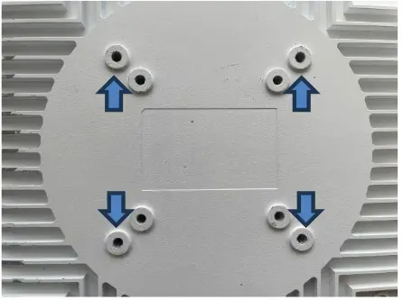
The AP750NRe AP has two sets of primary mounting holes and one set of secondary mounting holes at the bottom of the chassis for attaching third‐party mounting systems:
Third‐Party Mounting System Installation
![]() The installer or user assumes all liabilities unless the installation methods are explicitly stated in a warranty agreement between Everest Networks, Inc. and the third‐party installer.
The installer or user assumes all liabilities unless the installation methods are explicitly stated in a warranty agreement between Everest Networks, Inc. and the third‐party installer.
![]() The network coverage depends on the location and position of the AP750 access point.
The network coverage depends on the location and position of the AP750 access point.
The AP750NRe AP has two sets of primary mounting holes and one set of secondary mounting holes at the bottom of the chassis for attaching third‐party mounting systems:
![]() For added safety, use one set of the primary mounting holes and one set of secondary mounting holes for installing a third‐party mounting system.
For added safety, use one set of the primary mounting holes and one set of secondary mounting holes for installing a third‐party mounting system.
The inner set of primary mounting holes are 75 mm apart in both the horizontal and vertical directions and are tapped with a M4 x 0.7 mm thread pattern to a depth of 10 mm.
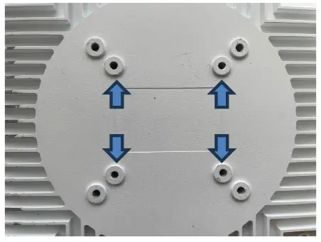
The outer set of primary mounting holes are 100 mm apart in both the horizontal and vertical directions and are tapped with a M6 x 1.0 mm thread pattern to a depth of 10 mm.
Installing GPS antenna
The external GPS antenna must be installed using standard SMA torque NRench. Use a 5⁄16 inch torque NRench is required for this antenna, set to 3–5 in·lbf (0.3 to 0.6 N·m).

Connectin g AP750NRe
Perform this procedure to connect the AP750NRe to the network.
A. Network supports PoE++ power (802.3bt)
- Attach one RJ45 plug to RJ45 receptacle (10GbE or 5GbE port) on the AP750NRe AP chassis.

- Connect the opposite end of the Ethernet cable to a PoE++ (802.3bt) source ▢ (PoE++ injector/midspan/switch).
When injector in midspan is used, connect the data port to an Ethernet switch port.
- Verify PoE++ source is providing power and Ethernet switch port has established link with the port.
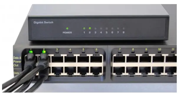
B. Network supports PoE+ power (802.3at)
- Attach the two RJ45 plugs to RJ45 receptacle on the AP750NRe AP chassis.

- Connect the opposite ends of both the Ethernet cables to a PoE+ (802.3at) source ▢ (PoE+ injector/midspan/switch).
When injectors in midspan are used, connect the data port to an Ethernet switch port.
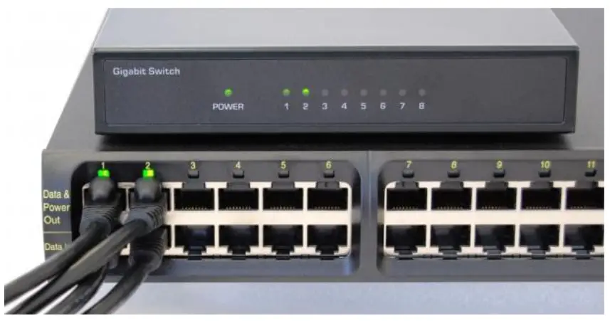
- Verify PoE+ source is providing power and Ethernet switch port has established link with both ports.
Chapter 3: Configuring AP750NRe
This section provides information and procedures required to configure the AP750NRe series AP.
Logging into BaseCamp
Perform this procedure to log into BaseCamp.
- Log into BaseCamp URL, https://<AC IP address> using the following credentials:
• Username: admin@admin.com
• Password: admin
Welcome to BaseCamp page is displayed.
Configuring AP750NRe Access Point
Perform this procedure to configure the AP750 series AP.
- Configure the POE+/++ ports of the L2/L3 switch as access ports with untagged PVID.
The PoE+/++ source must identify itself as PoE+/++ capable using the 2‐event classification method. For more information on configuring the AP750 series APs that are connected to POE+/++ sources that support a discovery protocol, see Configuring AP750 series AP to Work with Discovery Protocol. - Connect the AP750NRe Access Point to a POE+/++ source.
Once powered up, the AP750NRe Access Point requests an IP address from the DHCP server. This process may take up to 90 seconds. - Verify if the AP750NRe was assigned an IP address by doing one of the following:
• Review the DHCP logs on the DHCP server
• Log into BaseCamp to review the status in the Access Points page
Along with the IP address, the AP750NRe receives the IP address of the Access Controller and establishes a connection with it.

- The AP750NRe is manufactured with a default country code. During the discovery phase of the AP750 NRe, the Access Controller verifies the country code of the AP750 NRe before allowing it to join the network.
• If the country code registered in the non‐volatile memory of the AP750NRe and the country code locked into the Access Controller software match, the AP750NRe is allowed to join the network.
• If an AP750NRe is detected with a generic country code, the Access Controller registers the AP750NRe by overwriting the generic country code with the locked country code from the BaseCamp configuration. After updating the country code, the AP750 NRe is automatically rebooted allowing it to join the network.
• If the AP750NRe is set with a different country code, the AP750NRe is quarantined and not allowed to join the network.
 The transmitters on the radio modules in the AP750NRe are disabled when the country code is in generic state, or when the AP750NRe is quarantined.
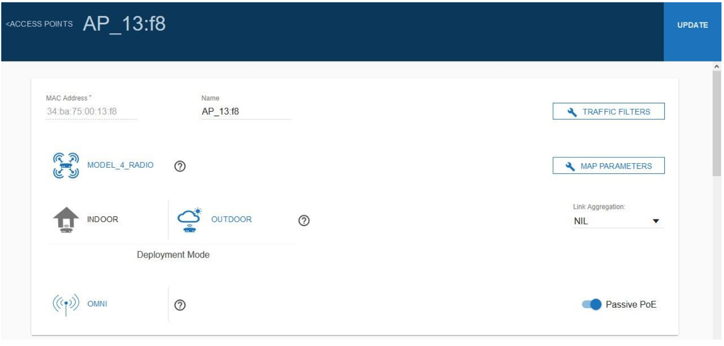
 - The default mode of operation for the AP750NRe is Outdoor. BaseCamp allows certified technicians with the appropriate privileges provided by the manufacturer to reconfigure the mode of operation to Indoor when the AP750NRe is installed in indoor locations.
a. From the BaseCamp navigation pane, click Access Points.
b. From the list of Access Points, click the Configure icon of the AP750NRe.
c. Modify the Deployment Mode:
• Indoor
• Outdoor
d. Click UPDATE.
Configuring AP750NRe to Work with Discovery Protocol
In some cases, a POE+/++ ethernet switch requires a Discovery Protocol such as LLDP and CDP to request additional power above the 15.4 W PoE PSE limit. In such cases, the POE+/POE++ PSE source must be configured to override the Discovery Protocol and force the PoE+/POE++ PSE source to provide at least 22.5 W/51W of PoE+/POE++ power.
Perform this procedure to configure the AP to work with Discovery Protocol.
![]() Use extreme caution. This is a manual mode of operation. There is no action taken by the AP750NRe, if PoE+ power is interrupted. Even a single port losing PoE+ power may result in an overload on the port.
Use extreme caution. This is a manual mode of operation. There is no action taken by the AP750NRe, if PoE+ power is interrupted. Even a single port losing PoE+ power may result in an overload on the port.
- In the WMS Access Point menu, set the Forced POE+ Power selection to flag the AP750NRe access point to ignore the POE+ status.
The AP750NRe AP automatically resets when the new Forced POE+ Power selection configuration is saved. All the AP750NRe hardware resources are available after rebooting the AP750NRe.
Chapter 4: AP750NRe Coverage
This section provides information on deployment options for optimal coverage from the AP750NRe access point.
AP750NRe Radiation Pattern
The unique design of the AP750NRe provides flexibility for various mounting positions and coverage footprints for all bands including UNII-1/2A/2C/3/5/7. With coverage distances up to 75ft, the AP750NRe provides ubiquitous coverage via its omni-directional radiation pattern with the unique ability to customize specific coverage footprints based on RF or venue requirements. In addition, custom narrow-band filtering is available to provide complete band-to-band RF isolation.
The following figure shows the radiation pattern for AP750NRe AP.
![]() For outdoor installation, the antenna must be positioned at least 45° downward from the vertical position.
For outdoor installation, the antenna must be positioned at least 45° downward from the vertical position.
Figure 3: AP750NRe AP Radiation Pattern

Regulatory Declarations
Federal Communication Commission Interference Statement
This equipment has been tested and found to comply with the limits for a Class B digital device, pursuant to Part 15 of the FCC Rules. These limits are designed to provide reasonable protection against harmful interference in a residential installation. This equipment generates, uses and can radiate radio frequency energy and, if not installed and used in accordance with the instructions, may cause harmful interference to radio communications. However, there is no guarantee that interference will not occur in a particular installation. If this equipment does cause harmful interference to radio or television reception, which can be determined by turning the equipment off and on, the user is encouraged to try to correct the interference by one of the following measures:
- Reorient or relocate the receiving antenna.
- Increase the separation between the equipment and receiver.
- Connect the equipment into an outlet on a circuit different from that to which the receiver is connected.
- Consult the dealer or an experienced radio/TV technician for help.
This device complies with Part 15 of the FCC Rules. Operation is subject to the following two conditions: (1 This device may not cause harmful interference, and (2 this device must accept any interference received, including interference that may cause undesired operation.
This device and its antennas must not be co‐located or operating in conjunction with any other antenna or transmitter.
Important Note:
FCC Caution: Any changes or modifications not expressly approved by the party responsible for compliance could void the user’s authority to operate this equipment.
Important Note:
Country Code selection feature are disabled for products marketed to the US/Canada.
IMPORTANT NOTE:
FCC Radiation Exposure Statement:
This equipment complies with FCC radiation exposure limits set forth for an uncontrolled environment. This equipment should be installed and operated with a minimum distance of 71 cm between the radiator & your body.
Appendix: Technical Specifications
This section provides technical specifications of the AP750 AP.
Mechanical Specifications
The following table provides mechanical specifications of the AP750 AP.
Table 1: Mechanical Specifications

Operational Requirements
The following table provides operational requirements of the AP750 AP.
Table 2: Operational Requirements

¹All power or Ethernet limits are defined as a per pair limit.
²Some frequency bands may not be operational in power limited operations.
Environmental Requirements
The following table provides environmental requirements of the AP750 AP.
Table 3: Environmental Requirements

© Copyright 2015 ‐ 2024 by Everest Networks, Inc., USA. All Rights Reserved.
Statement of Conditions
In the interest of improving internal design, operation function, and/or reliability, Everest Networks, Inc. reserves the right to make changes to products described in this document without notice. Everest Networks, Inc. does not assume any liability that may occur due to the use or application of the product(s) described herein.
Document Number: IG-AP750NRe-000
Revision: 1.x
Date: June 2024
AP750NRe Installation Guide
![]()
Documents / Resources
 |
EVEREST NETWORKS AP750NRe Wireless Access Point [pdf] Installation Guide 2AGMR-AP750NRE, 2AGMRAP750NRE, ap750nre, AP750NRe Wireless Access Point, AP750NRe, Wireless Access Point, Access Point |