![]()
EPcolor | Hardware Manual ver. 2.0 | Code 144PCOLORE204
EVCO S.p.A.
EPcolor
Code 144PCOLORE204
Programmable remote user interfaces (with Gui-PRO graphic tool)


PLEASE READ CAREFULLY and save this document
CONSIDER THE ENVIRONMENT
 Read this document carefully before installation and before using the device and take all the prescribed precautions. Keep this document with the device for future reference. Only use the device in the ways described in this document.
 The device must be disposed of according to local regulations governing the collection of electrical and electronic equipment.
INTRODUCTION
The color series is an elegant range of programmable remote user interfaces. The 3.5 inch (EPcolor S), 5 inches (EPcolor M) or 7 inch (EPcolor L) TFT graphic display is fully touch-screen. The color series is ideal for setting up user interfaces for applications developed on c-pro 3 programmable controllers. Thanks to the MODBUS protocol, they can also interact with third-party devices. Highly evolved user interfaces can be set up using a wide range of predefined library graphics and templates. Moreover, the ability to automatically import fonts, load bitmaps, and text translation files from a USB flash drive simplifies the human-machine interface personalization process.
N FEATURES OF THE MODELS AVAILABLE AND PURCHASING CODES
| PURCHASING CODES | EPCJ01X4 | – | EPCJ04X4V | EPCJ04T4V | EPCM01X4 | EPCM00X4 | EPCL00X4 | EPCL01X4 |
| Series | EPcolor S | EPcolor M | EPcolor L | |||||
| DISPLAY | ||||||||
| 3.5 inch TFT touch-screen colour graphic display | • | • | • | |||||
| 5 inch TFT touch-screen colour graphic display | • | • | ||||||
| 7 inch TFT touch-screen colour graphic display | • | • | ||||||
| INSTALLATION | ||||||||
| Panel-mounted | • | • | • | |||||
| From behind | • | • | ||||||
| Wall-mounted | • | • | ||||||
| POWER SUPPLY | ||||||||
| 24 VAC/12… 30 VDC not insulated | • | 0 | • | • | • | • | • | • |
| COMMUNICATIONS PORTS | ||||||||
| RS-485 MODBUS master | • | • | • | • | ||||
| RS-485 MODBUS slave | • | • | • | • | ||||
| RS-485 MODBUS master/slave | • | • | • | |||||
| CAN | • | • | • | • | • | • | • | |
| USB | • | • | • | • | • | • | • | |
| OTHER STANDARD FEATURES | ||||||||
| RTC | • | • | • | • | • | • | • | • |
| Alarm buzzer | • | • | • | • | • | • | • | • |
| Incorporated temperature sensor | • | |||||||
MEASUREMENTS AND INSTALLATION
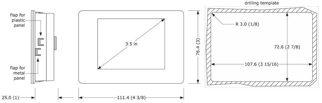
Measurements and installation of models in the color S series
Measurements are expressed in mm (inches).
Models to be fitted to a panel (with elastic holding flaps).
|
N.B. The metal panel must be between 0.8 and 1.5 mm (1/32 and 1/16 in) thick, while the plastic panel must be between 0.8 and 3.4 mm (1/32 and 1/8 in). |
Models to be mounted on the wall (with fixing screws and plugs) or in regular built-in boxes (with fixing screws).
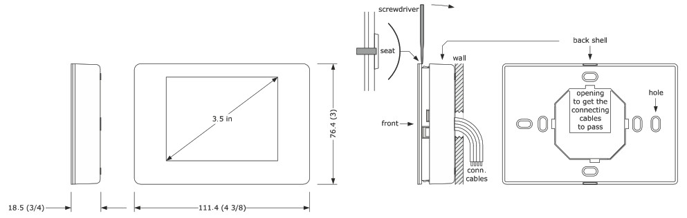
- Disengage the back cover from the front and the housing using a screwdriver.
- 2.1 Wall installation:
2.1.1 Rest the back cover on the wall in a place suitable for allowing the connection cables to feed through the opening.
2.1.2 Use the slots in the back cover as a guide for drilling the 4 holes with a diameter suitable for the plug.
We recommend using 5 mm (3/16 inch) diameter plugs.
2.1.3 Insert the plugs into the holes drilled in the wall.
2.1.4 Fit the back cover to the wall with 4 screws.
We recommend using flat countersunk screws.
2.2 Installation in a built-in box: fit the back cover to the box with 4 screws.
We recommend using flat countersunk screws. - Make the electrical connection as shown in the section ELECTRICAL CONNECTION, without powering up the device.
- Fit the front of the device to the back cover.
Measurements and installation of models in the color M series
Measurements are expressed in mm (inches).

Models to be installed from behind (using threaded studs).

Measurements and installation of models in the EPcolor L series
Measurements are expressed in mm (inches).
Models to be fitted to a panel (with elastic holding flaps).

Models to be installed from behind (using threaded studs).

INSTALLATION PRECAUTIONS
– ensure that the working conditions are within the limits stated in the TECHNICAL SPECIFICATIONS section
– do not install the device close to heat sources, equipment with a strong magnetic field, in places subject to direct sunlight, rain, damp, excessive dust, mechanical vibrations or shocks
– in compliance with safety regulations, the device must be installed properly to ensure adequate protection from contact with electrical parts. All protective parts must be fixed in such a way as to need the aid of a tool to remove them
ELECTRICAL CONNECTION
|
N.B. – use cables of an adequate section for the current running through them – to reduce any electromagnetic interference, connect the power cables as far away as possible from the signal cables and, if necessary, connect to an RS485 MODBUS network and/or a CAN network by using a twisted pair – for the CAN port of EPcolor S and EPcolor M use a ferrite (for example Essentra RKCF-08-A5) to which the conductors of the shielded cable must be wound with two coils |
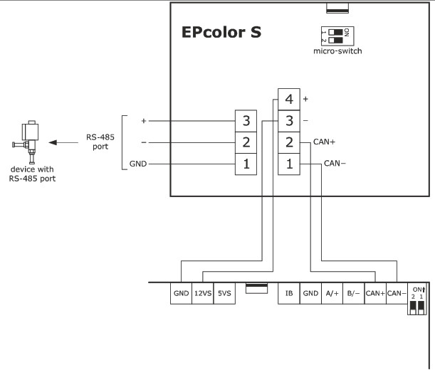
Electrical connection for models in the EPcolor S series
Connectors
Models to be fitted to a panel.

Connector 1
| CONN. | DESCRIPTION |
| 1 | RS-485 MODBUS port GND reference |
| 2 | signal – RS-485 MODBUS port |
| 3 | signal + RS-485 MODBUS port |
Connector 2
| CONN. | DESCRIPTION |
| 1 | signal – CAN port |
| 2 | signal + CAN port |
| 3 | device power supply (24 VAC/ 12… 30 VDC); if the device is powered by direct current connect the negative terminal |
| 4 | device power supply (24 VAC/ 12… 30 VDC); if the device is powered by direct current connect the positive terminal |
Connector 3
USB port to program the device.
Micro-switch
– to fit the termination resistor of the RS-485 MODBUS port
– to fit the termination resistor of the CAN port.
Models to be mounted on the wall.

Connector 1
| CONN | DESCRIPTION |
| 1 | signal – CAN port |
| 2 | signal + CAN port |
| 3 | device power supply (24 VAC/ 12… 30 VDC); if the device is powered by direct current connect the negative terminal |
| 4 | device power supply (24 VAC/ 12… 30 VDC); if the device is powered by direct current connect the positive terminal |
| 5 | RS-485 MODBUS port GND reference |
| 6 | signal – RS-485 MODBUS port |
| 7 | signal + RS-485 MODBUS port |
Connector 2
USB port to program the device.
Micro-switch
– to fit the termination resistor of the RS-485 MODBUS port
– to fit the termination resistor of the CAN port.
Example of electrical connection
Models to be fitted to a panel with an independent power source.
|
N.B. Do not power another device with the same transformer |

Models for panel installation powered by another device.
|
N.B. Make sure the current generated by the controller is enough to power the device |
Fitting the termination resistor of the RS-485 port and the CAN port
To fit the termination resistor of the RS-485 MODBUS port, place micro-switch 1 in the ON position.
To fit the termination resistor of the CAN port, place micro-switch 2 in the ON position.
The micro-switch is on the back of the device (first remove the back cover from the front).
Models to be fitted to a wall with an independent power source.
|
N.B. Do not power another device with the same transformer |

|
N.B. Make sure the current generated by the controller is enough to power the device |

Electrical connection for models in the color M series
Connectors

Connector 1
| CONN | DESCRIPTION |
| PE | appliance earthing |
| PE | appliance earthing |
Connector 2
| CONN. | DESCRIPTION |
| 36 | device power supply and RS-485 MODBUS master port GND reference |
| 35 | signal – RS-485 MODBUS master port |
| 34 | signal + RS-485 MODBUS master port |
| 33 | device power supply (24 VAC/12… 30 VDC) |
Connector 3
| CONN | DESCRIPTION |
| 30 | RS-485 MODBUS slave port GND reference |
| 31 | signal – RS-485 MODBUS slave port |
| 32 | signal + RS-485 MODBUS slave port |
Connector 4
| CONN. | DESCRIPTION |
| 27 | CAN port GND reference |
| 28 | signal – CAN port |
| 29 | signal + CAN port |
Connector 5
USB port to program the device.
Micro-switch 1
– to fit the termination resistor of the RS-485 MODBUS master port
– to fit the termination resistor of the RS-485 MODBUS slave port.
Micro-switch 2
To fit the termination resistor of the CAN port.
Example of electrical connection
|
N.B. Do not power another device with the same transformer |

Fitting the termination resistor of the RS-485 ports and the CAN port
To fit the termination resistor of the RS-485 MODBUS master port, place dip 1 of micro-switch 1 in the ON position.
To fit the termination resistor of the RS-485 MODBUS slave port, place dip 2 of micro-switch 1 in the ON position.
To fit the termination resistor of the CAN port, place micro-switch 2 in the ON position.
Electrical connection for models in the color L series
Connectors
Connector 1
USB port to program the device
Connector 2
| CONN. | DESCRIPTION |
| 27 | CAN port GND reference |
| 28 | signal – CAN port |
| 29 | signal + CAN port |
Connector 3
| CONN | DESCRIPTION |
| 30 | RS-485 MODBUS slave port GND reference |
| 31 | signal – RS-485 MODBUS slave port |
| 32 | signal + RS-485 MODBUS slave port |
Connector 4
| CONN. | DESCRIPTION |
| 33 | device power supply and RS-485 MODBUS master port GND reference |
| 34 | signal – RS-485 MODBUS master port |
| 35 | signal + RS-485 MODBUS master port |
| 36 | device power supply (24 VAC/12… 30 VDC) |
Connector 5
| CONN | DESCRIPTION |
| PE | appliance earthing |
| PE | appliance earthing |
Micro-switch 1
To fit the termination resistor of the CAN port.
Micro-switch 2
To fit the termination resistor of the RS-485 MODBUS slave port.
Micro-switch 3
To fit the termination resistor of the RS-485 MODBUS master port.
Example of electrical connection
|
N.B. Do not power another device with the same transformer |

Fitting the termination resistor of the RS-485 ports and the CAN port
To fit the termination resistor of the CAN port, place micro-switch 1 in the ON position.
To fit the termination resistor of the RS-485 MODBUS port, place micro-switch 2 in the ON position.
To fit the termination resistor of the RS-485 MODBUS port, place micro-switch 3 in the ON position.
PRECAUTIONS FOR ELECTRICAL CONNECTION
– if using an electrical or pneumatic screwdriver, adjust the tightening torque
– if the device is moved from a cold to a warm place, humidity may cause condensation to form inside. Wait for about an hour before switching on the power – make sure that the supply voltage, electrical frequency, and power are within the set limits. See the section TECHNICAL SPECIFICATIONS
– disconnect the power supply before carrying out any type of maintenance
– do not use the device as a safety device
– for repairs and further information, contact the EVCO sales network
TECHNICAL SPECIFICATIONS
Technical specifications of models in the EPcolor S series
| Purpose of the control device | Function controller |
| Construction of the control device | Built-in electronic device |
| Housing | Black, self-extinguishing |
| Category of heat and fire resistance | D |
| Measurements | |
| 111.4 x 76.4 x 25.0 mm (4 3/8 x 3 x 1 in) for panel installation models | 111.4 x 76.4 x 18.5 mm (4 3/8 x 3 x 3/ 4 in) for wall installation models |
| Mounting methods for the control device | According to the model, panel (with elastic holding flaps), wall (with fixing plugs and screws) or in regular built-in boxes (with fixing screws) |
| Degree of protection provided by the casing | IP30 (IP65 in the event of panel installation) |
| Connection method | |
| Plug-in screw terminal blocks for wires up to 1 mm² for panel installation models | Fixed screw terminal blocks for wires up to 1 mm² for wall-mounted models |
| The maximum permitted length for connection cables | |
| Power supply: 10 m (32.8 ft) | RS-485 MODBUS port: 1,000 m (3,280 ft) |
| CAN port: – 1,000 m (3,280 ft), baud rate: 20,000 baud – 500 m (1,640 ft), baud rate: 50,000 baud – 250 m (820 ft), baud rate: 125,000 baud – 50 m (164 ft), baud rate: 500,000 baud Over 10 m (32.8 ft) use a screened cable |
USB port: 1 m (3.28 ft) |
| Operating temperature | From -10 to 55 °C (from 14 to 131 °F) | ||
| Storage temperature | From -20 to 70 °C (from -4 to 158 °F) | ||
| Operating humidity Pollution status of the control device |
Relative humidity without condensate from 5 to 95% | ||
| 2 | |||
| Compliance | |||
| RoHS 2011/65/EC | WEEE 2012/19/EU | REACH (EC) Regulation no. 1907/2006 | |
| EMC 2014/30/EU | LVD 2014/35/EU | ||
| Power supply | 24 VAC (±15%), 50/60 Hz (±3 Hz), max. 4 VA not insulated or 12… 30 VDC, max. 2 W not insulated (independent power source or power generated by a controller) | ||
| Earthing methods for the control device | None | ||
| Rated impulse-withstand voltage Over-voltage category | 330 V | ||
| I | |||
| Software class and structure Clock | A | ||
| Built-in secondary lithium battery | |||
| Clock drift | S 55 s/month at 25 °C (77 °F) | ||
| Clock battery autonomy in the absence of a power supply Clock battery charging time |
> 6 months at 25 °C (77 °F) | ||
| 24 h (the battery Is charged by the power supply of the device) | |||
| Displays | 3.5-inch capacitive TFT touch-screen graphic display, 320×240 px, 256 colours | ||
| Alarm buzzer | Built-in | ||
| Incorporated sensors | Temperature (according to the model) | ||
| Incorporated sensors working range | From 0 to 40 °C (from 32 to 104 °F) | ||
| Program memory | 1 MB | ||
| For communications ports | |
| 1 RS-485 MODBUS master/slave port | 1 CAN port |
| 1 USB port | |
Technical specifications of models in the EPcolor M series
| Purpose of the control device | Function controller |
| Construction of the control device | Built-in electronic device |
| Housing | Black, self-extinguishing |
| Category of heat and fire resistance | D |
| Mounting methods for the control device | According to the model, to be installed from behind using threaded studs or to a panel with elastic holding flaps |
| Degree of protection provided by the casing | 1P40 (1P65 in the event of panel installation) |
| Connection method | Plug-in screw terminal blocks for wires up to 1 mm2 |
| Power supply: 10 m (32.8 ft) | RS-485 MODBUS ports: 1,000 m (3,280 ft) |
| CAN port: – 1,000 m (3,280 ft), baud rate: 20,000 baud – 500 m (1,640 ft), baud rate: 50,000 baud – 250 m (820 ft), baud rate: 125,000 baud – 50 m (164 ft), baud rate: 500,000 baud Over 10 m (32.8 ft) use a screened cable |
USB port: 1 m (3.28 ft) |
| Operating temperature | From 0 to 55 °C (from 32 to 131 °F) |
| Storage temperature | From -20 to 70 °C (from -4 to 158 °F) |
| Operating humidity | Relative humidity without condensate from 5 to 9 |
| Pollution status of the control device | 2 |
| Compliance | |
| RoHS 2011/65/EC | WEEE 2012/19/EU | REACH (EC) Regulation no. 1907/2006 |
| EMC 2014/30/EU | LVD 2014/35/EU | |
| EMC 2014/30/EU | LVD 2014/35/EU | |
| Power supply | 24 VAC (&15%), 50/60 Hz (+3 Hz), max. 6.5 VA not insulated or 12… 30 VDC, max. 3 W not insulated | |
| Earthing methods for the control device | None | |
| Rated impulse-withstand voltage | 330 V | |
| Over-voltage category | I | |
| Software class and structure | A | |
| Clock | Built-in secondary lithium battery | |
| Clock drift | 5 55 s/month at 25 °C (77 °F) | |
| Clock battery autonomy in the absence of a power supply | > 6 months at 25 °C (77 °F) | |
| Clock battery charging time | 24 h (the battery is charged by the power supply of the device) | |
| Displays | 5-inch capacitive TFT touch-screen graphic display, 800×480 px, 65K colours | |
| Alarm buzzer | Built-in | |
| Programme memory | 1 MB | |
| Communications ports | ||
| 1 RS-485 MODBUS master port | 1 RS-485 MODBUS slave port | |
| 1 CAN port | 1 USB port | |
Technical specifications of models in the EPcolor L series
| Purpose of the control device | Function controller |
| Construction of the control device | Built-in electronic device |
| Housing | Black, self-extinguishing |
| Category of heat and fire resistance | D |
| Measurements | |
| 216.0 x 156.0 x 50.0 mm (8 1/2 x 6 1/8 x 2 in) for models to be installed from behind | 192.95 x 131.95 x 47.0 mm (7 5/8 x 5 3/16 x 1 7/8 in) for panel installation models |
| Mounting methods for the control device | According to the model, to be installed from behind using threaded studs or to a panel with elastic holding |
| Degree of protection provided by the casing | IP40 (IP65 in the event of panel installation) |
| Connection method | Plug-in screw terminal blocks for wires up to 1 mm² |
| Maximum permitted length for connection cables | |
| Power supply: 10 m (32.8 ft) | RS-485 MODBUS ports: 1,000 m (3,280 ft) |
| CAN port: – 1,000 m (3,280 ft), baud rate: 20,000 baud – 500 m (1,640 ft), baud rate: 50,000 baud – 250 m (820 ft), baud rate: 125,000 baud – 50 m (164 ft), baud rate: 500,000 baud Over 10 m (32.8 ft) use a screened cable |
USB port: 1 m (3.28 ft) |
| Operating temperature | From 0 to 55 °C (from 32 to 131 °F) |
| Storage temperature | From -20 to 70 °C (from -4 to 158 °F) |
| Operating humidity | Relative humidity without condensate from 5 to 95% |
| Pollution status of the control device | 2 |
| Compliance | |
| RoHS 2011/65/EC | EE 2012/19/EU | REACH (EC) Regulation no. 1907/2006 |
| EMC 2014/30/EU | LVD 2014/35/EU | |
| Power supply | 24 VAC (±15%), 50/60 Hz (±3 Hz), max. 10 VA not insulated or 12… 30 VDC, max. 4.6 W not insulated |
| Earthing methods for the control device | None |
| Rated impulse-withstand voltage | 330 V |
| Over-voltage category | I |
| Software class and structure | A |
| Clock | Built-in secondary lithium battery |
| Clock drift | ≤ 55 s/month at 25 °C (77 °F) |
| Clock battery autonomy in the absence of a power | > 6 months at 25 °C (77 °F) |
| Clock battery charging time | 24 h (the battery is charged by the power supply of the device) |
| Displays | 7-inch capacitive TFT touch-screen graphic display, 800×480 px, 65K colours |
| Alarm buzzer | Built-in |
| Program memory | 1 MB |
| Communications ports | |
| 1 RS-485 MODBUS master port | 1 RS-485 MODBUS slave port |
| 1 CAN port | 1 USB port |
EVCO S.p.A.
EPcolor
Programmable remote user interfaces (with Gui-PRO graphic tools – 14/21
Code 144PCOLORE204
This document and the solutions contained therein are the intellectual property of EVCO and thus protected by the Italian Intellectual Property Rights Code (CPI). EVCO imposes an absolute ban on the full or partial reproduction and disclosure of the content other than with the express approval of EVCO. The customer (manufacturer, installer or end-user) assumes all responsibility for the configuration of the device. EVCO accepts no liability for any possible errors in this document and reserves the right to make any changes at any time without prejudice to the essential functions and safety features of the equipment.
EVCO S.p.A.
EPcolor | Hardware Manual ver. 2.0 | Code 144PCOLORE204
![]()
EVCO S.p.A.
Via Feltre 81, 32036 Sedico (BL) ITALY
phone +39 0437 8422 fax +39 0437 83648
email info@evco.it web www.evco.it
Documents / Resources
 |
EVCO EPcolor Programmable Remote Advanced Controllers [pdf] User Manual EPcolor, Programmable Remote Advanced Controllers, EPcolor Programmable Remote Advanced Controllers, Advanced Controllers, Controllers |