ESAB Mechtrac 1730 Mechtrac Sub Arc System
INSTRUCTION MANUAL
Mechtrac 1730/2100/2500/3000
Valid for: serial no. 0947-xxx-xxxx, LX644-xxxx-xxxx, LX416-xxxx-xxxx
EU DECLARATION OF INCORPORATION
FOR PARTLY COMPLETED MACHINERY
According to
Machine Directive 2006/42/EC, entering into force 17 May 2006
The Low Voltage Directive 2014/35/EU, entering into force 20 April 2016 The EMC Directive 2014/30/EU, entering into force 20 April 2016
The RoHS Directive 2011/65/EU, entering into force 2 January 2013

1. SAFETY
1.1 Meaning of symbols
As used throughout this manual: Means Attention! Be Alert!

DANGER!
Means immediate hazards which, if not avoided, will result in immediate, serious personal injury or loss of life.
![]()
WARNING!
Means potential hazards which could result in personal injury or loss of life.
![]()
CAUTION!
Means hazards which could result in minor personal injury.

WARNING!
Before use, read and understand the instruction manual and follow all labels, employer´s safety practices and Safety Data Sheets (SDSs).
1.2Safety precautions
Users of ESAB equipment have the ultimate responsibility for ensuring that anyone who works on or near the equipment observes all the relevant safety precautions. Safety precautions must meet the requirements that apply to this type of equipment. The following recommendations should be observed in addition to the standard regulations that apply to the workplace.
All work must be carried out by trained personnel well-acquainted with the operation of the equipment. Incorrect operation of the equipment may lead to hazardous situations which can result in injury to the operator and damage to the equipment.
1. Anyone who uses the equipment must be familiar with:
- its operation
- location of emergency stops
- its function
- relevant safety precautions
- welding and cutting or other applicable operation of the equipment
2. The operator must ensure that:
- no unauthorised person is stationed within the working area of the equipment when it is started up
- no-one is unprotected when the arc is struck or work is started with the equipment
3. The workplace must:
- be suitable for the purpose
- be free from drafts
4. Personal safety equipment:
- Always wear recommended personal safety equipment, such as safety glasses, flame-proof clothing, safety gloves
- Do not wear loose-fitting items, such as scarves, bracelets, rings, etc., which could become trapped or cause burns
5. General precautions:
- Make sure the return cable is connected securely
- Work on high voltage equipment may only be carried out by a qualified electrician
- Appropriate fire extinguishing equipment must be clearly marked and close at hand
- Lubrication and maintenance must not be carried out on the equipment during operation
WARNING!
Arc welding and cutting can be injurious to yourself and others. Take precautions when welding and cutting.

ELECTRIC SHOCK – Can kill
- Install and ground the unit in accordance with instruction manual.
- Do not touch live electrical parts or electrodes with bare skin, wet gloves or wet clothing.
- Insulate yourself from work and ground.
- Ensure your working position is safe

ELECTRIC AND MAGNETIC FIELDS – Can be dangerous to health
Welders having pacemakers should consult their physician before welding. EMF may interfere with some pacemakers.
Exposure to EMF may have other health effects which are unknown.
Welders should use the following procedures to minimize exposure to EMF:
- Route the electrode and work cables together on the same side of your body. Secure them with tape when possible. Do not place your body between the torch and work cables. Never coil the torch or work cable around your body. Keep welding power source and cables as far away from your body as possible.
- Connect the work cable to the workpiece as close as possible to the area being welded.

FUMES AND GASES – Can be dangerous to health
- Keep your head out of the fumes.
- Use ventilation, extraction at the arc, or both, to take fumes and gases away from your breathing zone and the general area.

ARC RAYS – Can injure eyes and burn skin
- Protect your eyes and body. Use the correct welding screen and filter lens and wear protective clothing.
- Protect bystanders with suitable screens or curtains.

NOISE – Excessive noise can damage hearing
Protect your ears. Use earmuffs or other hearing protection.

MOVING PARTS – Can cause injuries

- Keep all doors, panels, guards, and covers closed and securely in place.
- Have only qualified people remove covers for maintenance and troubleshooting as necessary.
- Keep hands, hair, loose clothing and tools away from moving parts.
- Reinstall panels or covers and close doors when service is finished and before starting the unit.

FIRE HAZARD
- Sparks (spatter) can cause fire. Make sure that there are no inflammable materials nearby.
- Do not use on closed containers.

HOT SURFACE – Parts can burn
- Do not touch parts bare handed.
- Allow cooling period before working on equipment.
- To handle hot parts, use proper tools and/or insulated welding gloves to prevent burns.
![]()
CAUTION!
This product is solely intended for arc welding.
![]()
WARNING!
Do not use the power source for thawing frozen pipes.
![]()
CAUTION!
Class A equipment is not intended for use in residential locations where the electrical power is provided by the public low-voltage supply system. There may be potential difficulties in ensuring electromagnetic compatibility of class A equipment in those locations, due to conducted as well as radiated disturbances.


NOTE!
Dispose of electronic equipment at the recycling facility!
In observance of European Directive 2012/19/EC on Waste Electrical and Electronic Equipment and its implementation in accordance with national law, electrical and/or electronic equipment that has reached the end of its life must be disposed of at a recycling facility.
As the person responsible for the equipment, it is your responsibility to obtain information on approved collection stations.
For further information contact the nearest ESAB dealer.

ESAB has an assortment of welding accessories and personal protection equipment for purchase. For ordering information contact your local ESAB dealer or visit us on our website.
2. INTRODUCTION
2.1 INTRODUCTION
Mechtrac is a motor driven gantry for use together with ESAB’s A2 welding equipment and power sources (LAF/TAF/Aristo 1000).
The control of the travel motor takes place over the PEK control unit where the desired speed can be set.
For more information regarding the PEK, refer to relevant instruction manuals and spare parts lists for the A2, A6 PEK Control Panel and the A2, A6 PEK Control Unit.
3. TECHNICAL DATA
| Travel speed | 0.2 – 2.0 m/min | ||||||||||||||||||
| Maximum load | 220 kg | ||||||||||||||||||
| Standard rail length | 3 m | ||||||||||||||||||
Equivalent continuous A-weighted noise pressure is below 70 dB (A).
| Drive motors (VEC) on the bogies: (both motors with conical shaft ends) |
0147 018 892 (right version) | ||||||||||||||||||
| 0147 018 902 (left version) | |||||||||||||||||||
| Gear ratio | 672:1 | ||||||||||||||||||
| Speed | 4000 rpm at 42 V | ||||||||||||||||||
| Wheel Ø | 100 mm (3.94 in.) | ||||||||||||||||||
| Wheel circumference | 314.16 mm (12.37 in.) | ||||||||||||||||||
4. INSTALLATION
4.1 General
NOTE!
The installation must be executed by a professional.
Read the separate instruction manuals supplied with the different modules that are to be fitted on the gantry.
For installation of:
- welding head A2SFE1/ A2 SGE1, refer to relevant instruction manual.
- welding head A2SF J1/ A2SF J1 Twin/ A2SG J1/ A2SG J1 4WD, refer to relevant instruction manual.
- welding power source LAF 631, refer to relevant instruction manual.
- welding power source LAF 1001/ 1000M, refer to relevant instruction manual.
- • welding power source TAF 801, refer to relevant instruction manual.
• welding power source Aristo 1000, refer to relevant instruction manual.
Voltage supply
• Disconnect the voltage supply before starting the installation!
4.2 Assembly/ Disassembly
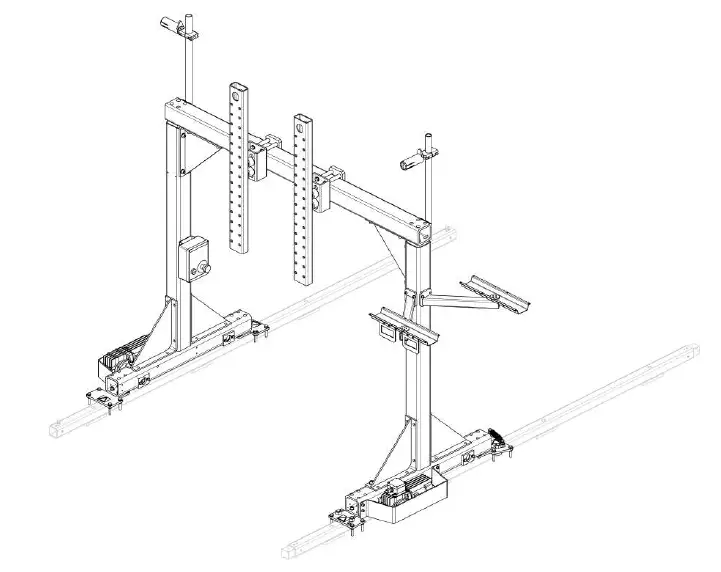
The picture below shows an example of how to attach an A2 welding head, flux container, wire bobbin and slide to the gantry.
1. Gantry
2. Welding head
3. Flux container
4. Wire bobbin
5. Slide
6. Bracket

The graphic below presents recommended location of the PEK and PAV/GMH units. The welding power sources (Aristo 1000 in the example below) should be placed on the floor, outside the Mechtrac working area, beside the Mechtrac gantry, approximately in the middle of the total travel length.

1. PEK 1
2. PEK 2
3. PAV/GMH 1
4. PAV/GMH 2
5. Power source 1
6. Power source 2
7. Emergency stop box
8. VEC motor
Make sure all the comprised modules are properly fastened. Loose parts falling off can involve danger and even unbalance when lifting.
NOTE!
The maximum weight allowed on the gantry is 220 kg.

When necessary use a lifting strap for lifting the different modules.
Use a lifting device when dismounting the bracket. The lifting device is to be mounted in the holes (7) on top of the bracket.
4.3 External emergency stop
For connection of the emergency stop placed on the gantry leg, refer to the connection instructions in the “DIAGRAM” section of this manual.
4.4 Emergency stop circuit
For connection of the emergency stop circuit between the PEK and the welding power source (LAF/TAF or Aristo 1000), refer to the connection instructions applicable to LAF/ TAF or Aristo 1000, in the “DIAGRAM” section.
5. CONFIGURATION
After installation, PEK must be configured with correct parameter (gear ratio and diameter of feed rollers) for the welding head and also travel motor on Mechtrac (gear ratio and wheel diameter). In the “Machine configuration” section of the A2, A6 PEK Control Panel manual, the procedure is described.
Wire feed axis
| USER DEF. AXIS | |||||||||||||||||||
| Motor | VEC 4000 | ||||||||||||||||||
| Gear 1 | Gear ratio to be found in the manual for the welding head in question | ||||||||||||||||||
| Gear 2 | 1:1 | ||||||||||||||||||
| Diameter feed rollers | Feed roller diameter to be found in the manual for the welding head in question | ||||||||||||||||||
| Pulse sensor | 32 ppr | ||||||||||||||||||
| Low manual speed | 150 cm/min | ||||||||||||||||||
| Hign manual speed | 300 cm/min | ||||||||||||||||||
Travel axis
| USER DEF. AXIS | |||||||||||||||||||
| Motor | VEC 4000Par | ||||||||||||||||||
| Gear 1 | 672:1 | ||||||||||||||||||
| Gear 2 | 1:1 | ||||||||||||||||||
| Diameter feed rollers | 100 mm | ||||||||||||||||||
| Pulse sensor | 32 ppr | ||||||||||||||||||
| Hign manual speed | 200 cm/min | ||||||||||||||||||
6. OPERATION AND MAINTENANCE
6.1 General
CAUTION!
Have you read and understood the safety information?
You must not operate the machine before then!
General safety regulations for handling the equipment can be found in the “SAFETY” chapter of this manual. Read it through before you start using the equipment!
CAUTION!
All warranty undertakings from the supplier cease to apply if the customer attempts any work to rectify any faults in the product during the warranty period.
Voltage supply
Disconnect the voltage supply before carrying out any maintenance work!
For operation and maintenance, refer to each manual for PEK, A2 welding equipment and power sources (LAF/TAF/Aristo 1000) respectively.
6.2 Emergency Stop
Mechtrac is provided with an emergency stop (E).
Resetting after Emergency Stop:
1. Find and eliminate the cause of the emergency stop.
2. Pull out the emergency stop button.
3. ○ If the gantry is used together with a LAF power source, press “Reset”.
○ If the gantry is used together with an Aristo 1000 power source, press the power button on the Aristo power source.
If the gantry is used together with two Aristo 1000 power sources, then also press the power button on Aristo power source number two.
NOTE!
An emergency stop must not be reset until the cause for the abnormal function or signal has been defined and remedied.

Test and Check of Emergency Stop
CAUTION!
The function of all emergency and safety devices is to be checked regularly, at least once every month, as well as after any work has been carried out on the equipment.
NOTE!
Any abnormal function or signal must be defined and remedied before the Mechtrac unit is put into operation.
7. ORDERING SPARE PARTS
Spare parts and wear parts can be ordered through your nearest ESAB dealer, see esab.com. When ordering, please state product type, serial number, designation and spare part number in accordance with the spare parts list. This facilitates dispatch and ensures correct delivery.
ORDERING NUMBERS

Technical documentation is available on the Internet at: www.esab.com
DIMENSION DRAWING

Rail foundation
The rails must be attached to the ground e.g. with expansion anchor bolts size M8. The foundation must be of good quality, concrete C25 or better.
Use metal sheets of different thickness to adjust the rail according to dimensions.
DIAGRAM
Mechtrac single welding head with PAV/GMH and LAF

Mechtrac dual welding heads with PAV/GMH and LAF

Mechtrac single welding head with PAV/GMH and Aristo 1000

Mechtrac dual welding heads with PAV/GMH and Aristo 1000

Mechtrac dual travel motor

Connections when using LAF power sources
Mount XT80 in an appropriate place in LAF/ TAF

Connections when using Aristo 1000 power sources
Mount XT80 in an appropriate place in Aristo 1000.

ACCESSORIES
| A2 GMAW (Gas Metal Arc Welding) | ||||||||||||
| 0414 191 881 | Cooling unit OCE 2H | |||||||||||
| 0190 270 102 | Gas hose | |||||||||||
| 0190 315 104 | Water hose | |||||||||||
| A2 SAW (Submerged Arc Welding) | ||||||||||||
| 0413 541 882 | Conversion kit Twin | |||||||||||
| 0461 248 880 | Conversion kit A2 SAW→ MIG/MAG | |||||||||||
| 0153 872 880 | Plastic wire reel | |||||||||||
| 0416 492 880 | Steel wire reel | |||||||||||
| 0148 140 880 | Flux recovery unit A6 OPC | |||||||||||
| 0190 343 102 | Air hose | |||||||||||
| 0145 221 881 | Flux funnel | |||||||||||
| 0443 570 880 | Air drying unit A6 CRE 30 | |||||||||||
| 0153 143 886 | Pilot lamp | |||||||||||
| 0457 788 880 | Laser lamp | |||||||||||

For contact information visit esab.com
ESAB AB, Lindholmsallén 9, Box 8004, 402 77 Gothenburg, Sweden, Phone +46 (0) 31 50 90 00

Documents / Resources
 |
ESAB Mechtrac 1730 Mechtrac Sub Arc System [pdf] Instruction Manual 1730, 2100, 2500, 3000, Mechtrac 1730 Mechtrac Sub Arc System, Mechtrac 1730, Mechtrac Sub Arc System, Sub Arc System, Arc System, System |


