![]() Low Bay Ruggedized Radio
Low Bay Ruggedized Radio
Module, 8-pin
Install Guide Low Bay Ruggedized Radio Module
RM-6E Low Bay Ruggedized Radio Module
Shipped Components
- Low Bay Ruggedized Radio Module (RM-6E-8W-LR)
Supplemental Components
- Enlighted Sensor Cable
- Enlighted Control Unit
Tools you will Need
- Locknut (Optional)
- Flat blade screwdriver
Caution
A qualified electrician must perform installation and maintenance under local, state, and national electrical codes (NEC) and requirements. For installations outside of North America, qualified personnel must conform to appropriate standards when installing and maintaining products powered by FELV circuits, such as some DALI installations.
 DO NOT use an HCMC to mount the Radio Module to a ceiling tile. The module needs to be secured with a locknut.
DO NOT mount the Radio Module if the mounting accessory has the following defects: - Knockout hole has a ridge inside that prevents the Radio Module from going all the way in.
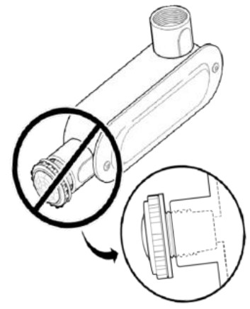
- The mounting accessory faceplate does not have a large flat surface area for the Radio Module to fit snugly against.

- The Radio Module lens protrudes out and does not fit securely into the knockout hole.
- A gap exists between the washer and the surface of the mounting accessory.

![]() WARNING: When the Radio Module are installed incorrectly, it can cause water leakage, electrical shock, and the unit to fail.
WARNING: When the Radio Module are installed incorrectly, it can cause water leakage, electrical shock, and the unit to fail.
To avoid the possibility of exceeding the FCC and ISED radio frequency exposure limits, human proximity to the radiator shall not be less than 20cm during normal operation.
Installation Procedure
Before proceeding with the Radio Module
installation, make sure to de-energize the luminaire.
Note: The black bezel will be attached with the O-ring in place when you receive it. When using the white bezel, make sure that the O-ring is in place under the bezel.
Fixture Mount Radio Module Installation
Step 1: Identify an outdoor fixture that has an industry standard ½” (12.7 mm) -13 threaded mounting hole to which the Radio Module is to be mounted.
 Step 2: Insert the Radio Module through the mounting hole and thread the module until the washer makes contact with the fixture surface.
 Step 3: Continue to tighten the Radio Module with a ¼ turn to make sure that the module fits in snugly to prevent water leakage.
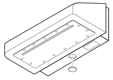
Sheet Metal Radio Module Installation
Step 1: Drill a 7/8″ (22mm) knock-out hole in the sheet metal.
Note: For sheet metal mounting, the ½” Lock nut must be ordered separately.
Step 2: Insert the Radio Module through the knock out hole with the lens facing down.
 Step 3: Thread the locknut tightly from behind the sheet metal to secure the Radio Module to prevent water leakage.
Connecting the Radio Module Cable to the Control Unit
Step 1: Connect one end of the Radio Module cable to the Control Unit (CU). For wiring connections from the Control Unit to the module, refer to the Control Unit Installation Guide.
Step 2: Connect the luminaire and confirm that the LED status is solid green with two brief blinks.
LED Description
Note: The purpose of wiring test is to serve as a sanity check regarding connectivity to the Radio Module. However, the overall responsibility of the quality of the device must meet the QC criteria for the light fixture manufacturer.
| LED Status | Description/Solution |
| LED not ON | • In uncommission state: The Radio Module is not powered ON. Check power and wiring. • In commission state: Radio Module is commissioned and running normally. |
| Solid Green with two brieblinks | The uncommissioned Radio Module has powered up successfully and completed the wiring test with no unexpected conditions – waiting for discovery. |
| BlinkingRed | The uncommissioned Radio Module has powered up and completed the wiring test with one or more conditions unexpected of a typical LED fixture – waitingfor discovery. |
| Solid Red | Faulty Radio Module – replace the Radio Module. |
| Solid Blue | Radio Module receiveda request to identify itself. |
| Blinking Blue | The uncommissioned Radio Module powered up successfully, but the module is unable to detect an energy measurement device (Control unit), waiting for discovery. |
| Blinking Magenta | When the Radio Module is connected to the control unit that is currently in the process of an emergency test or an emergency test pending. |
Copyright © 2024 Enlighted Inc. All rights reserved.
All other brand or product names are trademarks of their respective companies or organizations.
Company Contact Information
Location: 3979 Freedom Circle, #210,
Santa Clara, CA 95054
Phone: +1.650.964.1094
Web: enlightedinc.com
DoCs: https://www.enlightedinc.com/eu-docs/
Support Portal: support.enlightedinc.com
Model No. RM-6E
Product Code: RM-6E-8W-LR
Power: : 180mW
FCC ID: AQQ-SU6E
IC: 10138A-SU6E

This device complies with Part 15 of the FCC Rules and Innovation, Science and Economic Development Canada’s license-exempt RSS standard(s). Operation is subject to the following two conditions: (1) This device may not cause harmful interference, and (2) This device must accept any interference received, including interference that may cause undesired operation of the device.
Changes or modifications not expressly approved by Enlighted could void the user’s authority to operate the equipment.
![]()
Documents / Resources
 |
Enlighted RM-6E Low Bay Ruggedized Radio Module [pdf] Installation Guide RM-6E, RM-6E-8W-LR, RM-6E Low Bay Ruggedized Radio Module, RM-6E, Low Bay Ruggedized Radio Module, Ruggedized Radio Module, Radio Module, Module |