EMS TSD019-99 Loop Module User Guide

Iphone: https://apple.co/3WZz5q7
Android: https://goo.gl/XaF2hX
Step 1 – Install panel & loop module
The control panel and loop module require installation into their proposed locations. See the Fusion loop module installation guide (TSD077) for more information.
Once the control panel and loop module are installed and power is applied, the loop module will show the following default screen:
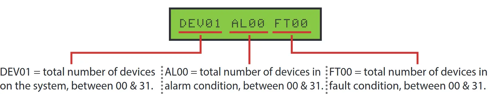
Note: As default, the loop module will be set to device address 001. This can be changed if required. For further details download the Fusion loop module programming manual (TSD062) from www.emsgroup.co.uk
Step 2 – Power up the devices
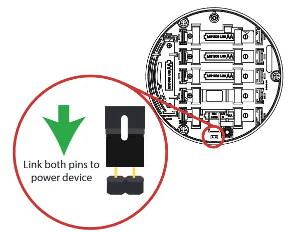
Detectors, sounders, call points and input/ output units have power jumpers as shown:
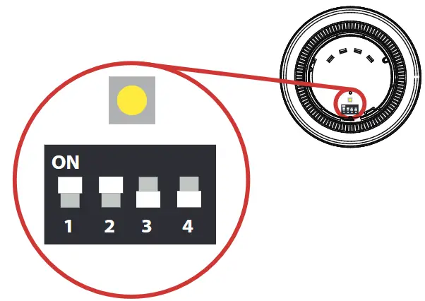
Combined sounder detectors are powered by changing the orientation of switch 1 as shown:
Switch 1 on = POWER ON
Step 3 – Add & install devices
To log on the devices; the loop module must be in the correct operating menu and then the device log on button pressed until the red confirmation led lights next to the button (note on the call point the alarm led is utilised for this feature).
From front display![]() Add New Device
Add New Device ![]() screen displays Press Dev Log On followed by Add Dev 03456 Y?
screen displays Press Dev Log On followed by Add Dev 03456 Y?![]() select required address
select required address ![]() Detector Added.
Detector Added. ![]() to exit.
to exit.
The device now requires installation to its location. (See associated device installation guide for more information).
Step 4 – Add devices to control panel
The devices will now require adding to the connected control panel, ensuring consistency of device addresses with the loop module. Note: combined sounder/detectors will hold two loop addresses. (The first for it’s sounder and the next for it’s detector).
Step 5 – Check device signal levels
Device signal levels can be found in the Signal Level menu:
From front display ![]() Device Status
Device Status ![]() select desired device
select desired device![]() Signal Level
Signal Level
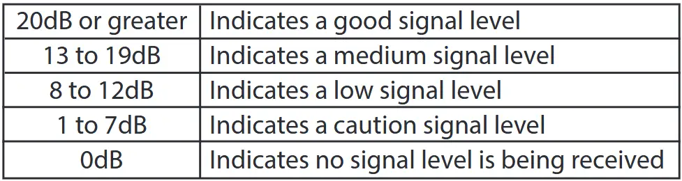
This menu shows information on the two signalling channels used by the loop module. The displayed signal levels range from 0 to 45dB, with 45 being the highest signal and 0 being the lowest (where no signal is being seen). All signal levels are shown below:
![]() to exit.
to exit.
Step 6 – Test devices
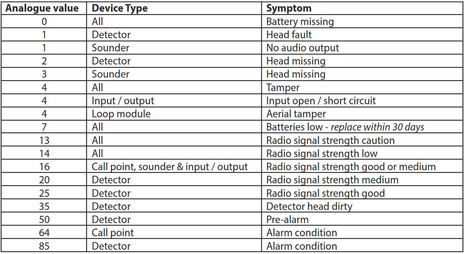
The system can now be tested to ensure correct operation. Available analogue values are listed below:
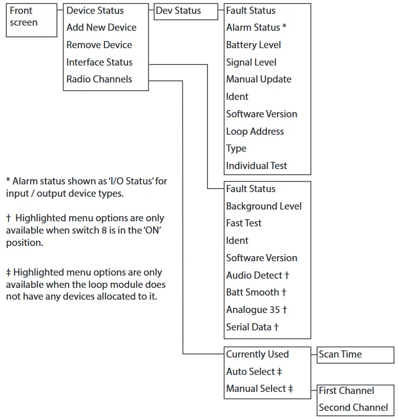
Menu structure
The information contained within this literature is correct at time of publishing. EMS reserves the right to change any information regarding products as part of its continual development enhancing new technology and reliability. EMS advises that any product literature issue numbers are checked with its head office prior to any formal specification being written.

http://www.emsgroup.co.uk/contact/
Documents / Resources
 |
EMS TSD019-99 Loop Module [pdf] User Guide TSD019-99, TSD077, TSD062, TSD019-99 Loop Module, TSD019-99, Loop Module, Module |