elvaco CMi4140 LoRaWAN Module External Antenna Kit

Specifications
- Mechanics:
- Dimensions (w x h x d)
- Weight
- Mounting
- External antenna connector
- Electrical Connections:
- Supply voltage
- Electrical characteristics:
- Nominal voltage
- Power consumption (max)
- Power consumption (sleep mode)
- Environmental Specifications:
- Operating temperature
- Operating humidity
- Operating altitude
- Pollution degree
- Usage environment
- Storage temperature
Product Usage Instructions
- Pulse inputs In A and In B allow connecting adjacent pulse meters.
- Power connector and MCX antenna connector are provided.
- Grab the device by the outer edges and gently press it into the module slot.
- Connect the power connector to the meter power supply.
Module Activation via Elvaco OTC App
- Open Elvaco OTC app (available for Android and iOS).
- Scan the module (ensure NFC is activated on the phone).
- Go to Apply mode, set power mode to Active, and select Apply settings.
- Scan the module again to apply new settings.
Verifying Module Activation
To verify activation, go to Inspect, scan the module, and ensure the power mode is set to Active.
Additional Tips and Cautions
If using an external antenna, ensure it is mounted at least 0.5 meters away from the meter to prevent interference.
Introduction
- CMi4140 is a meter connectivity module mounted inside a Kamstrup MULTICAL 403/603/803 heating/cooling meter to deliver meter data to a receiving server via a LoRaWAN® network. The module is energy-efficient and offers 11 years of battery lifetime with EcoMode enabled. It can be retrofitted into deployed meters and is ideal for applications where long-range is required. CMi4140 is easily configured through Elvaco OTC mobile app, or via downlink commands.
- With CMi4140, Elvaco offers a meter connectivity module designed for customers who require a user-friendly and cost-effective solution.
- For a complete description of the product, or for information in other languages, visit the Elvaco AB support website, http://support.elvaco.com.
Parts overview

- Pulse inputs In A and In B (allowing to connect adjacent pulse meters)
- Power connector
- MCX antenna connector
Mounting the product
CMi4140 can be used in either a Kamstrup MULTICAL® 403, MULTICAL® 603a, or a MULTICAL® 803 heat/cooling meter. If the module is not mounted in the meter upon delivery, it is easily inserted and installed:
- Grab the device by the outer edges.
- Gently press it into position in the module slot.
- Connect the power connector to the meter power supply.
CAUTION
This is an electrostatic-sensitive product. Observe the necessary ESD protective measures when installing the product.
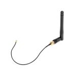
Connection of the LoRaWAN® antenna
CMi4140 has an option for using either an internal or an external LoRaWAN® antenna. Since both antennas are using the MCX connector, they are interchangeable.
- Connect the internal or external or antenna with MCX connector to the module in the meter.
- Route the antenna cable (if using an external antenna)
- Push the connector gently into the socket on the module.
CAUTION
If using an external antenna, make sure to mount it at least 0.5 meters away from the meter in order not to cause interference.
Activating the module
NOTE: Before activating the module, and trying to join a LoRaWAN® network, make sure the LoRaWAN® network server of use is prepared with necessary device and security-related information. Security keys for Elvaco devices can be accessed in Elvaco EVO, Elvaco EVO Login.
Upon delivery, the module is set to inactive mode, which means no messages will be transmitted from the module before being activated. The module can be activated either via the buttons on the meter, or via the Elvaco OTC App:
Module activation via meter buttons
- On MULTICAL® 403, press and hold both buttons on the front of the meter until “CALL” is displayed.
- On MULTICAL® 603 and MULTICAL® 803, press down the two arrow buttons on the front of the meter until “CALL” is displayed.
Module activation via Elvaco OTC App
- Open Elvaco OTC app (available for Android and iOS).
- Scan the module (make sure NFC is activated on the phone).
- Go to Apply mode.
- Set the power mode to Active.
- Select Apply settings.
- Scan the module to apply new settings.
To verify that the module has been activated, go to Inspect, scan the module, and make sure that power mode is set to Active.
TIP
- If the module is mounted inside a MULTICAL® 403, the NFC field is easiest accessible if placing your phone in the middle of the higher part of the back.
- MULTICAL® 603 has two module slots. If mounted in the left module slot, the NFC field is easiest accessible if placing your phone in the middle of the higher part of the back. If the module is mounted in the right module slot, place your phone to the right of the higher part of the back.
- If the module is mounted in MULTICAL® 803, the meter needs to be open to access the NFC field. Place your phone close to the CMi4140 when making the NFC scan.
Joining the LoRaWAN® network
- When activated, the module will attempt to join the LoRa-WAN® network. If the module fails to join the LoRaWAN® network it will perform retries until it succeeds. The time be-tween each attempt will increase for every attempt until it’s performed once every day. A new join attempt cycle can be manually started anytime by deactivating and activating the module using the Elvaco OTC App.
- When the module has joined the LoRaWAN® network, me-ter data will initially be transmitted from the module every minute (regardless of transmit interval settings) in order to set the right data rate. After three minutes of calibration, the module will start to deliver meter data using its configured settings. By using the Elvaco OTC App, you can easily verify that the module is successfully communicating with the meter (“Meter communication”) and is connected to the LoRaWAN® network (“Network joined”).
LoRaWAN® network end-device activation
Before being able to transmit data over a LoRaWAN® net-work, the module must be personalized and activated. This can be done in two different ways for LoRaWAN®, Over-the-air activation (OTAA) or Activation by Personalization (ABP). For security reasons, Elvaco strongly recommends using OTAA, where all network keys are generated each time the module joins the LoRaWAN® network. In contrast, for ABP, all keys are set manually and stay constant over time.
In OTAA mode
Before the module is able to transmit messages via the LoR-aWAN® network, device information needs to be added to the network server. More specifically, the following parame-ters needs to be registered in order to enable the network server to receive messages from the module:
Device EUI 16 digit module unique identification number. It is not configurable.
Application key
The application key of each device is generated by Elvaco and used in OTAA mode to generate network keys when the module joins the LoRaWAN® network.
Keys are managed in a secure way using Elvaco’s
- OTC (One Touch Commissioning) solution which includes the mobile application for configuration.
- JoinEUI Sets the identification number of the join server. The identification number is set to a default value in all devices.
- The default value is presented in Elvaco OTC configuration options.
In ABP mode
If the activation mode is set to ABP, the application key does not need to be added to the network server. Instead the following information will be needed:
Network session key
Used by both the module and the network server.
Application session key
- Used for payload encryption and decryption.
- Device address Unique identifier of the module.
Simplified Declaration of Conformity Hereby, Elvaco declares that CMi4140 is in compliance with the following directives:
EU UK
- 2014/53/EU (RED) 2017 No. 1206 (RED)
- 2014/30/EU (EMC) 2016 No. 1091 (EMC)
- 2014/35/EU (LVD) 2016 No. 1101 (LVD)
- 2011/65/EU + 2015/863 (RoHS) 2012 No. 3032 (RoHS)
- See EU Declaration of Conformity for a complete EU DoC.
- See UK Declaration of Conformity for a complete UK DoC
Technical specifications
- Mechanics Value
- Dimensions (w x h x d) 90 x 12 x 35 mm
- Weight 33 g
- Mounting In module slot of Kamstrup MULTICAL® 403/603/803
- External antenna connector MCX
- Electrical connections Value
- Supply voltage Internal meter battery (up to 11 years lifetime, having EcoMode enabled, using Kamstrup’s D-Cell meter battery).
- Electrical characteristics Value
- Nominal voltage 3.0 VDC
- Power consumption (max) 50 mA
- Power consumption (sleep mode) 2.5 μA
- Environmental specifications Value
- Operating temperature +5 – +55 ºC
- Operating humidity 0 – 93 % RH, no condensation
- Operating altitude 2000 m
- Pollution degree Degree 1
- Usage environment Indoors
- Storage temperature -20 – 60 ºC
- Radio characteristics Value
- Frequency 868 MHz
- Output power 14 dBm
- Receiver sensitivity -135 dBm
- LoRaWAN® characteristics Value
- Device class Class A, bi-directional
- LoRaWAN® version 1.0.2
- Activation OTAA or ABP
- Data rate DR0 – DR5 (250 bit/s-5470 bit/s)
- User interface Value
- Push button Start-up/reboot / switch off module
- Configuration NFC via Elvaco OTC app or downlink data
- Approvals Value
- LoRa Alliance® LoRaWAN CertifiedCM
- EMC EN 301489-1, EN 301489-3
FAQ
In OTAA Mode vs. ABP Mode
In OTAA mode, the device EUI, application key, and JoinEUI are essential. In ABP mode, network session key, application session key, and device address are required.
Declaration of Conformity
The product complies with EU directives including RED, EMC, LVD, and RoHS. Refer to the Declaration of Conformity for detailed information.
Documents / Resources
 |
elvaco CMi4140 LoRaWAN Module External Antenna Kit [pdf] Instruction Manual CMi4140, CMi4140 LoRaWAN Module External Antenna Kit, LoRaWAN Module External Antenna Kit, Module External Antenna Kit, External Antenna Kit, Antenna Kit |