EchoStar Mobile EM2050 Hardware Module User Guide

Version History

Index of Figures

Index of Tables

Copyright © 2022 by EchoStar Mobile Limited. All rights reserved. No part of the contents of this guide may be or transmitted in any form or by any means without the written permission of the publisher.
This guide is for the use of technology partners of EchoStar Mobile. Part of the contents of this guide may be transmitted to partner’s subcontractor under confidential agreement between partner and partner’s subcontractor. It is provided “as is” and without warranty of any kind.
EchoStar Mobile, the EchoStar Mobile logo are trademarks or registered trademarks of the EchoStar group of companies. All other marks are property of their respective owners.
List of Abbreviations

1 Introduction
This document serves to act as a developer’s guide for solution integrators looking to integrate the EM2050 module as part of their new or existing products. It provides an overview of the module and includes all relevant information to allow them to develop solutions with it as the core wireless transmission module. This simplifies the process of partners and system integrators in utilising the EchoStar Mobile Satellite LoRa network as part of their IoT Solutions and allowing them to deliver value to partners and customers.
2 EM2050 Hardware Module Overview
2.1 Features
- Designed for operation on EchoStar Mobile’s Pan European Licensed S-Band LoRa Network
- Single CPU Multi Region Application Module
- Low Power Consumption: Typical 320mA Active Transmit, 80mA Receive and 25μA Sleep
- Small Single Board form factor: 32 x 47 x 4mm Including RF Shield
- Multi LoRaWAN and LoRa Frequency Support: EU 868MHz, USA 915MHz ISM and Licensed S-Band
- LoRaWAN Class A and C compatible
- TX Power of 27dBm in Licensed S-Band
- TX Power of 14/22dBm in 868/915MHz ISM Bands
- 50 Byte Payload size utilising SF12 and LR-FHSS
- Built in temperature and supply voltage sensing
- Fully Compliant with local certification requirements
2.2 EM2050 Hardware Architecture
The EM2050 Module incorporates several components in addition to the Semtech LR1120 to enable a complete system in module. This allows the Module to operate on EchoStar Mobile’s S-Band LoRa Network as well as the 868/915MHz ISM Bands. This approach allows a simplified product design process for system integrators allowing the module to handle the complexities of the Satellite S-Band Network.
2.3 Hardware Variants
There is currently only one variant of the EM2050 module available, this is outlined below. The options available will evolve long term based on customer feedback and demand.
- EM2050-0 – Base version not equipped with U.FL antenna connectors and utilising STM32WB15 MCU
2.4 Software Revisions

2.5 Applications
The EchoStar Mobile OEM Module is a perfect fit for many industries and use cases, its wide range of operation, flexible operating structure and low power consumption allow it to be utilised in a wide range of use cases such as below.
- Remote Asset Tracking
- Fixed Asset monitoring
- Battery Powered remote devices
3 Regulatory Certification
The EM2050 module is a regulatory approved transceiver that meet CE, FCC and ISED requirements according to the following table:

Certification and Declaration of Conformity can be shared on demand.
3.1 FCC warning statement
This device complies with part 15 of the FCC Rules. Operation is subject to the following two conditions:
- this device may not cause harmful interference
- this device must accept any interference received, including interference that may cause undesired operation.
This equipment has been tested and found to comply with the limits for a Class B digital device, pursuant to part 15 of the FCC Rules. These limits are designed to provide reasonable protection against harmful interference in a residential installation. This equipment generates, uses and can radiate radio frequency energy and, if not installed and used in accordance with the instructions, may cause harmful interference to radio communications. However, there is no guarantee that interference will not occur in a particular installation. If this equipment does cause harmful interference to radio or television reception, which can be determined by turning the equipment off and on, the user is encouraged to try to correct the interference by one or more of the following measures:
– Reorient or relocate the receiving antenna.
– Increase the separation between the equipment and receiver.
– Connect the equipment into an outlet on a circuit different from that to which the receiver is connected.
– Consult the dealer or an experienced radio/TV technician for help.
The module complies with FCC radiation exposure limits for uncontrolled environment.
Note:
The modular transmitter is only FCC and ISED authorized for FCC Part 15C and 25 and ISED RSS-GEN, RSS-247 and RSS-170. The host product manufacturer is responsible for compliance to any other FCC rules or ISED standards that apply to the host not covered by the modular transmitter grant of certification.
Additional Testing, Part 15 Subpart B Disclaimer:
the final host product still requires Part 15 Subpart B compliance testing with the modular transmitter installed.
3.1.1 EMI Consideration
A host manufacture is recommended to use D04 Module Integration Guide recommending as “best practice” RF design engineering testing and evaluation in case non-linear interactions generate additional non-compliant limits due to module placement to host components or properties For standalone mode, reference the guidance in D04 Module Integration Guide and for simultaneous mode7; see D02 Module Q&A Question 12, which permits the host manufacturer to confirm compliance.
3.2 Industry Canada warning statement
This device contains license-exempt transmitter(s)/receiver(s) that comply with Innovation, Science and Economic Development Canada’s license exempt RSS(s). Operation is subject to the following two conditions: (1) This device may not cause interference. (2) This device must accept any interference, including interference that may cause undesired operation of the device.
This radio transmitter has been approved by Innovation, Science and Economic Development Canada to operate with the antenna types listed below, with the maximum permissible gain indicated. Antenna types not included in this list that have a gain greater than the maximum gain indicated for any type listed are strictly prohibited for use with this device.
ICES-003 Class B Notice -Avis NMB-003 Classe B:
This Class B digital device complies with Canadian ICES-003
CAN ICES-3(B) / NMB-3(B)
4 Mechanical Characteristics
4.1 Module Dimensions and Weight
The OEM Module is assembled on a single sided 1mm thick PCB with castellated pins, ready to be soldered on an existing PCB developed by the system integrator. The mechanical drawings, step file and footprint to be imported into Altium can be found in this document’s complementary components. A summary of the mechanical characteristics can be found below in Table 1 – Mechanical Characteristics


4.2 Environmental Conditions
The module conforms to the following environmental conditions

4.3 Reflow Profile and Soldering Process
The EM2050 module is designed to be surface mounted with castellated terminations utilising gold plated solder lands, the module employs a lead-free manufacturing process with lead free soldering paste. EM2050 module is compatible with the industrial reflow profile for common SAC type RoHS solders and a No-clean soldering paste is recommended.
As with any reflow profile it is dependent on the thermal mass over the entire area of the host PCB, the heat transfer from the oven and the type of solder paste utilised. The optimal soldering profile must be tweaked slightly depending on the PCB layout and specific soldering process.
The parameter values shown in the table below are guidelines that we recommend for mounting the EM2050 modules to your PCBs using a Pb-free process.


5 Electrical Characteristics
5.1 Pinout
The table below defines the module pinout available at the castellated connections surrounding the PCB.


There are two configurations possible for breaking out the RF signal paths, by default the paths are connected to the OEM Module pinouts as described below in Table 3 – Default RF Signal Paths. In this configuration the RF path must be broken out to the antenna by the system integrator along a 50-ohm impedance trace.

It is also possible to remove the 0 Ohm resistors and solder U.FL connectors on the OEM module board to take advantage of alternative RF signal paths as seen in Table 4 – Alternative RF Signal Paths.

5.2 Power Requirements
The OEM Module requires a stabilised 3.3V DC Power Supply capable of delivering 500mA for 2 second intervals when operating at full power. If powered via a battery with a high internal resistance it is recommended that stabilisation of the supply voltage is implemented to ensure stable operation of the EM2050 Module.
The table below provides some examples of typical current draw of the EM2050 module during normal modes of operations.

In Figure 3 – Transmit and Receive Window at Full Power (27dBm) you can see the EM2050 Module’s typical power consumption during the transmission of a packet and then the power consumption during the RX window after this. Further detailed information and a whitepaper on the power consumption of the EM2050 module will be available in due course across a range of power levels. Only approved Antenna designs should be used, the module’s current consumption is highly dependent on the exact implementation of these.

6 Radio Frequency Overview
6.1 S-Band RF Characteristics
There are two discrete S-Band RF ports on the OEM module to allow narrowband antennas to be utilised for the TX and RX of signals as they operate on different frequencies.
6.1.1 S-Band TX P35
In the default configuration the S-Band TX Port is broken out on P35 or J5(non-default config) and has a typical maximum output power of +27dBm with a frequency range of 1980-2010MHz, an antenna centred on this frequency should be used for optimal performance. EchoStar Mobile will provide a list of approved antennas for use with the module. The output power can be reduced if sufficient link budget is available and detected by the application MCU using the ADR feature of the EM2050 Module.
6.1.2 S-Band RX P41
In the default configuration the S-Band RX Port is broken out on P41 or J4(non-default config) and includes all necessary circuitry for external noise rejection on the frequency range of 2170-2200MHz, an antenna centred on this frequency should be utilised for optimal performance. EchoStar Mobile will provide a list of approved antennas for use with the module.
6.2 ISM-Band RF Characteristics
When operating in the ISM 868/915MHz bands there is a single signal path broken out from the OEM Module on P44 in default configuration or J3 if a U.FL connector is utilised. This input is then multiplexed internally by an RF switch to ensure that the signal path is connected to the relevant RF port on the LR1120 based on the current action being performed. The OEM module incorporates all relevant filtering necessary to meet harmonic and emissions limits when operating in the 868 and 915MHz bands at the relevant legal power levels. These power levels are 14dBm in the 868MHz band and 22dBm in the 915MHz bands.
6.3 RF working mode
The heart of the EM2050 module is the LR1120 radio transceiver from Semtech. It is a very powerful chip with the following features:
– A high frequency PA (HF PA), optimized for +13dBm operation in the 2.4GHz band and used for S-Band operation (2.1Ghz) in LoRa® and LoRa-FHSS up to 11.5dBm
– A low power PA (LP PA), optimized for +14dBm operation working on Sub-GHz operation on 868 / 915MHz ISM bands
– High power PA path +22dBm in the Sub-GHz band, only available when operating in the 915MHz ISM band
– GNSS reception of raw pseudo-range data for low-power position determination
– SPI interface to MCU
The following figure shows the LR1120 block diagram:

LR1120 has one single transmitter modulator that can be used in one of the following 3 RF output ports (one at a time, not simultaneously):
- the RFO_HF port has been enabled in TX and operates in the S-Band: 1980-2010MHz for TX. Operation up to 2020MHz for US band is supported.
- The RFO_HP_LF port is the high-power sub-GHz TX port, connected to the sub-GHz TX switch U4, port 2. This port is able to operate up to +22dBm power output (US 915MHz only).
- The RFO_LP_HF port is the low-power sub-GHz TX port, connected to the sub-GHz TX switch U4, port 3. This port is able to operate up to +14dBm power output.
LR1120 has also 3 RF input ports used in Rx:
- the RFI_HF port is available but is not used in RX mode.
- The RFI_LF0 port is the sub-GHz RX input port and is connected to the sub-GHz RF switch matrix U5. This port is used to receive from ISM band or from S-Band through a Fixed IF downconverter (U10 PLL + U7 Mixer).
- The RFI_LF1 port is connected to the internal GNSS antenna and is therefore capable of autonomous, low-power geolocation in addition or in alternative to an external GNSS receiver (if provided by the system integrator).
Note for more details on LR1120 please refer to Semtech LR1120 user manua
Echostar has developed a dedicated firmware for EM2050, derived by Semtech, to configure and control the frequency band in use, identified in LoRaWAN as Region;
Below the details of AT command to be used to set the active LoRa Region to use
AT+REGION LoRaWAN Region Select: sets the active LoRaWAN region.
AT+REGION=? displays
AT+REGION: Show/set current LoRaWAN Region. Supported regions: MSS-S, EU868, US915
AT+REGION? displays current value
AT+REGION?
Current Default Region: MSS-S
OK
To change the active region enter AT+REGION=<region> which can be one of the following values: MSS-S, EU868, US915; The device will automatically save the new configuration in Flash and restart a new Join procedure with the new regional parameters, e.g.:
AT+REGION=MSS-S
New Default Region: MSS-S
Saving and applying new configuration…
OK
INFO: LoRaMac stack initialized @ 01/01/1970 02:21:43
WARNING: Restarting LoRaWAN stack with new region MSS-S, rejoining network. @ 01/01/1970 02:21:43
As shown in the commands above, only one region can be active at a time, therefore the device cannot operate simultaneously on more than one band.
6.4 Antenna characteristics
For FCC Max allowed antenna gain for sub-GHz Band is 10dBi and max allowed antenna gain for S-Band is 7.5dBi with a Duty cycle 100%, as reported in the filing.
For ISED Max allowed antenna gain for sub-GHz Band is 10dBi and max allowed antenna gain for S-Band is 6.7dBi with a Duty cycle 100%, as reported in the filing.
Recommended antenna for S-Band is the PCB omnidirectional antenna type EMAS100 made by EchoStar Mobile Ltd. with a transmission gain of 0 dBi
Recommended antenna for terrestrial ISM bands are any commercially available antennas with gain lower than 10dBi and impedance 50 Ohm.
7 Operating the OEM Module
7.1 LED Indicators
The EM2050 Module is equipped with two LED indicators to provide visual feedback on the current state of the EM2050 Module Radio MCU, these can be disabled if required to further reduce the power consumption of the EM2050 Module by issuing the command AT+LED=0.

Table 6 – LED Behaviour
7.2 Communicating with the OEM Module
By default, the application MCU should communicate with the OEM Module via P1 for RX and P3 for TX utilising the following serial port parameters as defined below.
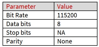
Table 7 – Serial Port Parameters
In addition to the RX and TX lines there are two additional handshake lines used for communicating with the OEM module available on P19 and P20, these are used to signal to the application MCU that the OEM module is asleep and cannot receive or send commands, this also works in reverse from the application MCU to the OEM module.
7.2.1 Communication Flow
RTS is a signal from the Application MCU to the OEM board. It must be configured as an open-drain I/O with internal pullup on the Application MCU.
When the Application MCU is in active mode and ready to receive data, RTS signal P20 must be driven LOW, and the pullup may be switched off to reduce power consumption.
When the Application MCU is in sleep mode, this signal must be configured as an interrupt-generating input with internal pullup. The Radio MCU will wake up the Application MCU by driving P20 signal LOW for approx. 10 usec, then the signal will be floated and pulled up by the Application MCU.
When the Application MCU has woken up and is ready to receive data, it will drive RTS LOW.
On the opposite side, the CTS signal P19 behaves in the same way.
CTS is a signal from the OEM board to the Application MCU. It is configured as an open-drain I/O with internal pullup R11 on the OEM Board.
When the OEM Board is in active mode and ready to receive data, CTS signal P19 will be driven LOW.
When the OEM Board is in sleep mode, this signal is configured as an interrupt-generating input with internal pullup R11. The Application MCU will wake up the OEM Board by driving the CTS/P19 signal LOW for at least 10 μsec, then the signal must be floated and will be pulled up by the OEM Board, R11.
When the OEM Board has woken up and is ready to receive data, it will drive CTS/P19 LOW.
EchoStar Mobile EM2050 Hardware Module Developers Guide V1.3.docx.
EchoStar Mobile Limited – We reserve the right to make changes to improve the product without prior notification at any time.
Read More About This Manual & Download PDF:
Documents / Resources
 |
EchoStar Mobile EM2050 Hardware Module [pdf] User Guide 2A8O9-EM2050, 2A8O9EM2050, em2050, EM2050 Hardware Module, EM2050, Hardware Module, Module |