DirectOut RAV2 Module Audio Network Module
RAV2 Module
Specifications:
- Software Manual Version: 2.8
- Audio network module for RAVENNA / AES67
- Browser-based interface (HTML5 / JavaScript)
- Resizable window and zoom level
- Organized in tabs, pulldown menus, and hyperlinks
- Supports input fields for parameter values (e.g., IP address)
- Two independent network interfaces (NICs)
- Port 1 is fixed assigned to NIC 1
Product Usage Instructions
Connecting Audio Network:
Before connecting the audio network, ensure that NIC 1 and NIC 2 are configured to different subnets. Follow the steps below:
- Access the “Network Settings” on page 7 of the user manual
- Configure NIC 1 and NIC 2 with different subnets
Status – Overview:
The “STATUS” tab provides an overview of various sections:
- Monitoring sync state, clock selection, links to I/O settings
- Display network info, link to network settings
- Monitoring device info, link to device settings, phones level control
- Links to input stream settings and output stream settings
Hyperlinks open a popup window for adjusting related settings. Most settings are updated immediately without further notification.
To exit a popup window, click the button in the top right corner.
Mouse overs display additional information, such as the connection speed of the network link.
Status – Sync:
The “Sync” section on the “STATUS” tab displays the following information:
- Clock source and state for the main frame
- Pulldown menu to select clock source of the main frame (PTP, extern)
- Pulldown menu to adjust sample rate of the main frame (44.1 / 48 / 88.2 / 96 / 176.4 / 192 kHz)
- State of PTP (Master / Slave)
- PTP-clock jitter per second
- Offset relative to PTP-clock master
- Status of packet processing (OK, Error*)
- State of module’s audio engine – receiving (ON / blinking)
- State of module’s audio engine – sending (ON / blinking)
*Error: packet time stamps are out of bounds. Possible reasons: stream offset may be too small or transmitter or receiver are not synced properly to the Grandmaster.
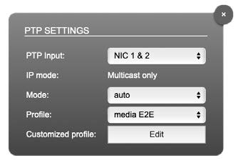
PTP Settings:
The “PTP Settings” section allows you to configure PTP input:
- NIC selection for PTP clock input. “NIC 1 & 2” means input redundancy.
- PTP via multicast, unicast, or in hybrid mode*
- PTP-clock master / slave configuration is auto-negotiated between devices in the network. The module’s master / slave state may change automatically.
- PTP profile selection (default E2E, default P2P, media E2E, media P2P, customized)
- Edit opens the “ADVANCED” tab to adjust the custom profile.
FAQs
Q: What is RAV2 Module?
A: RAV2 Module is an audio network module for RAVENNA / AES67.
Q: How can I access the device settings?
A: Access the “STATUS” tab and click on the corresponding links to access device settings.
Q: How can I adjust the clock source and sample rate?
A: On the “STATUS” tab, use the pulldown menus to select the desired clock source and adjust the sample rate.
Q: What does the blinking state indicate for the audio engine?
A: The blinking state indicates that not all received packets can be processed or not all packets can be sent to the network.
Introduction
RAV2 is an audio network module for RAVENNA / AES67.
All functions of the device are accessible through a browser based interface
(hmtl5 / javascript). The size of the window and the zoom level can be varied. The page is organized in tabs, pulldown menus or hyperlinks offer access to the values of a parameter. Some values use an input field (e.g. IP address).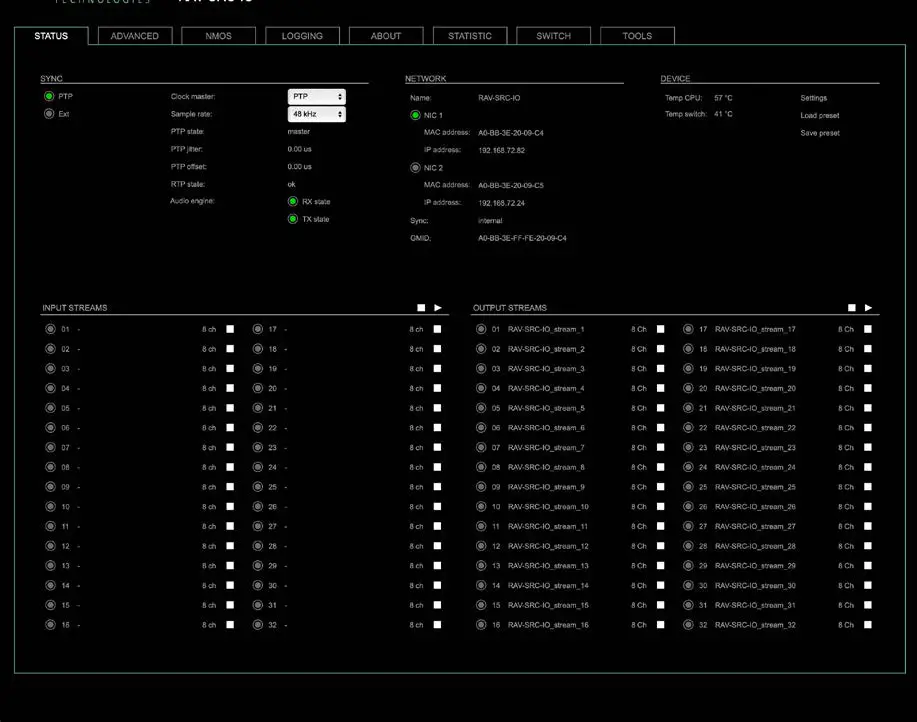
Connecting Audio Network
To access the control page:
- connect the network with one port
- enter http://<IP Address> (default IP @ PORT 1: 192.168.0.1) in the navigation bar of your browser
Two independent network interfaces (NICs) can be configured in the switch configuration. Port 1 is fixed assigned to NIC 1.
NOTE
If NIC 1 and NIC 2 are connected to the same switch, they must be configured to different subnets – see “Network Settings” on page 7.
Status – Overview
The tab ‘STATUS’ is divided into several sections:
- SYNC – monitoring sync state, clock selection, links to I/O settings
- NETWORK – display network info, link to network settings
- DEVICE – monitoring device info, link to device settings, phones level control
- INPUT STREAMS – monitoring and control input streams, link to input stream settings
- OUTPUT STREAMS – monitoring and control output streams, link to output stream settings
Hyperlinks open a popup window to adjust related settings. Most settings are updated immediately without further notification. To exit a popup window click the button in the top right corner.
Mouse overs are used to display further information (e.g. connection speed of network link).
NOTE
The web user interface updates itself when changes are applied by other instances (other browsers, external control commands).
Status – Sync
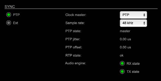
| PTP, Ext | Displays clock source and state for the main frame:
|
| Clock master | Pulldown menu to select clock source of the main frame (PTP, extern) |
| Sample rate | Pulldown menu to adjust sample rate of the main frame (44.1 / 48 / 88.2 / 96 / 176.4 / 192 kHz). |
| PTP state | State of PTP (Master / Slave). |
| PTP jitter | PTP-clock jitter per second |
| PTP offset | Offet relative to PTP-clock master |
| RTP state | Status of packet processing (OK, Error*) |
| Audio engine RX state | State of module’s audio engine- receiving
|
| Audio engine TX state | State of module’s audio engine- sending
|

 (blinking) = not all received packets can be processed
* Error: packet time stamps are out of bounds.
Possible reasons: stream offset may be too small or transmitter or receiver are not synced properly to the Grandmaster.
Hyperlinks:
PTP / PTP state (p 5)
PTP Settings
| PTP Input | NIC selection for PTP clock input. ‘NIC 1 & 2’ means input redundancy. |
| IP Mode | PTP via multicast, unicast or in hybrid mode. * |
| Mode | PTP-clock master/slave configuration is auto-negotiated between devices in the network. Module’s master/slave state may change automatically. |
| Profile | PTP profile selection (default E2E, default P2P, media E2E, media P2P, customized) |
| Customized profile | Edit opens the tab ‘ADVANCED’ to adjust the custom profile. |
See „Advanced – PTP Clock Setting“ on page 31 for more details.
Status – Network
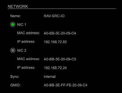
| Name | Module’s name in the network. Used e.g. for mDNS service. The name needs to be unique throughout the network. |
| NIC 1 / NIC 2 | Monitoring state of network interface controller
|
| MAC address | Hardware identification of network interface controller. |
| IP address | IP address of device |
| Sync | Selected NIC for PTP sync |
| GMID | Grand Master ID (PTP) |
Hyperlinks
Name / IP address (p 7)
Mouse over:
- LED NIC 1 – indicating link state and connection speed
- LED NIC 2 – indicating link state and connection speed
NOTE
If NIC 1 and NIC 2 are connected to the same switch, they must be configured to different subnets – see “Network Settings” on page 7.
Network Settings
The two network interface controllers (NIC 1 / NIC 2) are configured individually.
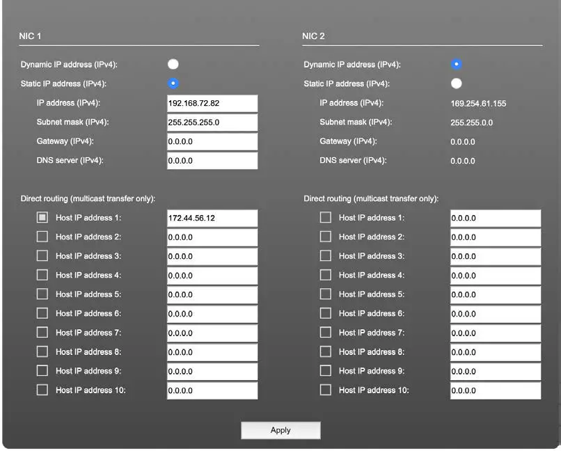
| Device name | Input field – Module’s name in the network. Used
e.g. for mDNS service. The name needs to be unique throughout the network. |
| Dynamic IP address (IPv4) | Switch to enable the device’s DHCP client.
IP address is assigned by DHCP server. If no DHCP is available the IP address is determined via Zeroconf. |
| Static IP address (IPv4) | Switch to disable the device’s DHCP client. Manual configuration of network parameters. |
| IP address (IPv4) | Module´s IP Address |
| Subnet mask (IPv4) | Module’s subnet mask |
| Gateway (IPv4) | IP address of gateway |
| DNS server (IPv4) | IP address of DNS server |
| Apply | Button to confirm changes. Another popup window will appear to confirm a reboot of the module. |
| Direct routing | IP addresses of devices outside the subnet, to enable multicast traffic; e.g. Grandmaster or IGMP querier.
Mark checkbox to activate. |
Status – Device
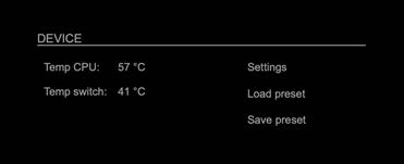
| Temp CPU | Display temperature of CPU core in degree Celsius. It may reach 95 ºC without effecting the performance of the device. |
| Temp switch | Display temperature of network switch in degree Celsius |
| Settings | Opens a popup window to configure the device. |
| Load preset | Opens a dialog to store the device settings to a file. Filetype: .rps |
| Save preset | Opens a dialog to restore the device settings from a file.
Filetype: .rps |
Hyperlinks:
- Settings (p 8)
- Load preset (p 9)
- Save preset
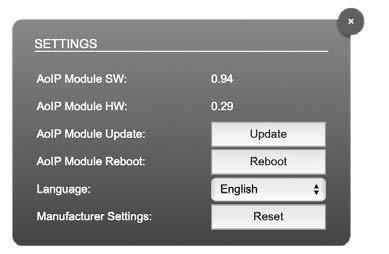
Settings
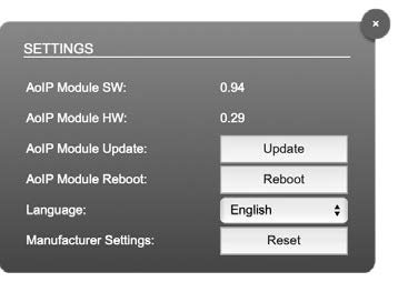
| AoIP Module SW | Module´s software version. It is updated together with hardware version via network. |
| AoIP Module HW | Module´s bitstream version. It is updated together with software version via network. |
| AoIP Module Update | Opens a dialog for selection of the update file – see “RAV2- Firmware Update” on page 43. |
| AoIP Module Reboot | Restart of the AoIP module. Confirmation required. Audio transmission will be interrupted. |
| Language | Menu language (english, german). |
| Manufacturer Settings Reset | Restore device settings to factory defaults. Confirmation required. |
Load Preset
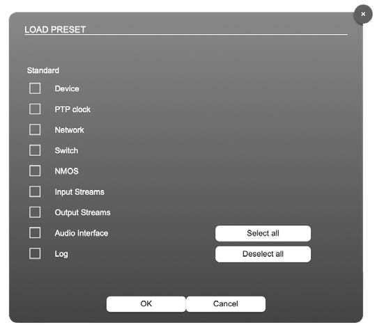
The device configuration can be stored to a single file (.rps).
Restoring the configuration a dialog prompts for selection of individual settings. This enhances flexibility at setup changes when a particular adjustment shall be preserved or just a single adjustment shall be restored.
Status – Input Streams
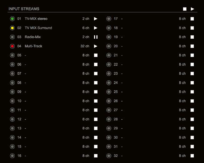 The module can subscribe up to 32 streams. The overview displays the basic information of each stream. The input stream name can be set manually
(discovery protocol: manually, see page p 19) overriding the SDP’s stream name information.
A backup stream can be defined as source after an adjustable timeout. A central active / inactive switch allows to toggle the stream state of all input streams at once.
| 01 to 32 | State of incoming streams
(unicast, connection not established) |
| 01 to 32 Name | Name of stream gathered from SDP or set manually in the stream settings dialog. |
| 01 to 32 xx ch | Number of audio channels transported by the stream |

| 01 to 32
|
Click to activate or deactivate single stream.
|
| INPUT STREAMS
|
Click to activate or deactivate all streams.
|


Backup Streams
 Example:
Backup stream (input 3) that will act as source in the audio matrix if the current session (input 1) fails. Switch-over occurs after the defined timeout (1s). Stream 3 is marked accordingly in the status view
 Input 1 failed and Input 3 becomes active after the timeout.
NOTE
In case the main input fails the main stream is stopped (IGMP LEAVE) before the backup stream is being activated. This behaviour ensures that the required network bandwidth does not increase in case of a failure.
 Hyperlinks:
- Name (p 14)
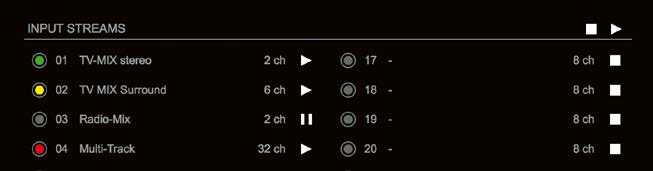
Mouse over:
- LED – indicating stream state
NOTE
Source-Specific Multicast (SSM) support for IGMP v3, v2 and v1 (SSM via protocol only in IGMP v3, SSM via internal filtering is applied for IGMP v2 and v1) – see “Source Specific Multicast” on page 19.
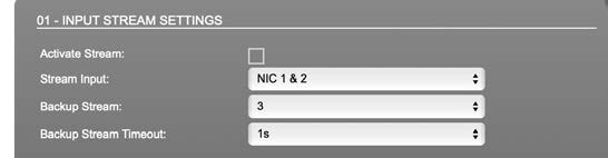
Input Stream Settings
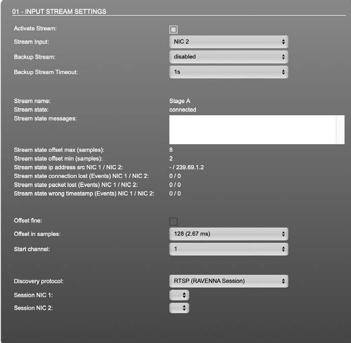 Up to 32 input streams can be subscribed. Each stream is organized in a
‘RAVENNA session’ (SDP = Session Description Protocol) that describes the stream parameters (audio channels, audio format, etc.).
The stream settings allow to adjust the processing of the received audio data (offset, signal routing). The receiving of stream data starts once the stream has been enabled.
The settings displayed vary depending on the selected discovery protocol.
TIP
A sample offset of at least doubled packet time (samples per frame) is recommended
Example: Samples per frame = 16 (0.333 ms) ➭ Offset ≥ 32 (0.667 ms)
It may be helpful to alter the stream discovery protocol if an expected stream can’t be discovered by the device.
| Activate stream | Stores parameters and activates or deactivates the receiving of audio data. (Unicast: additionally the negotiation of the connection) |
| Stream input | Selects one or both NICs used for stream input. Both NICs means input redundancy. |
| Backup Stream | Selects a backup stream that will act as source in the audio matrix if the current session fails. Switch-over occurs after the defined timeout. |
| Backup Stream Timeout | Defines timeout [1 s to 120 s] before switch-over to backup stream. |
| Stream name | Name of stream gathered from SDP |
| Stream state | Information about stream state: connected
not connected receiving data read successfull error |
| Stream state message | Status info related to stream state. |
| Stream state offset max | Measured value (maximum). A high value indicates that the media offset of the source might not match the adjusted media offset of the device. |
| Stream state offset min | Measured value (minimum). The offset should not become negative. |
| Stream state ip address src NIC 1 / NIC 2 | Multicast address of input stream subscribed at NIC 1 / NIC 2.
Unicast transmission: IP address of sender. |
| Stream state connection lost NIC 1 / NIC 2 | counter indicates the number of incidents where the network connection was lost (link down) |
| Stream state packet lost (Events) NIC 1 / NIC 2 | counter indicates the number of lost RTP packets |
| Stream state wrong timestamp (Events)
NIC 1 / NIC 2 |
counter indicates the number of packets with invalid timestamp |
| Offset fine | Enables adjustment of offset in increments of one sample. |
| Offset in samples | Modules output delay of received audio data (input buffer). |
| Start channel | Assignment of first stream channel in the audio matrix. E.g. stream with two channels, starting at channel 3 is available at channel 3 & 4 of the routing matrix. |
| Discovery protocol | Connection protocol or manual setup. RTSP = Real Time Streaming Protocol SAP = Session Announcement Protocol |
| Session NIC 1 | Selection of discovered streams at NIC 1 |
| Session NIC 2 | Selection of discovered streams at NIC 2 |
Stream Discovery in AoIP environments is a colorful mixture of different mechanisms. To serve a successful stream management RAV2 provides a bunch of options, not making operation easier but effective.
 Discovery RTSP (Session)
 Discovery RTSP (URL)
| URL | URL (Uniform Ressource Locator) of the session of the device that is serving streams.
Examples: rtsp://192.168.74.44/by-id/1 or rtsp://PRODIGY-RAV-IO.local:80/by-name/Stage_A |
| Receive SDP | Recalls the stream configuration of the defined session(s). |
NOTE
In case the automatic stream announcement and discovery of RAVENNA streams fails or cannot be used in a given network, the stream‘s SDP file can also be obtained via an RTSP URL.
Discovery SAP SAP is used in Dante environments.
Discovery NMOS

| Session | [MAC Address of sender] stream name @NIC |
| Refresh | Initiates a scan for available streams. |
NMOS is suited for use in SMPTE ST 2110 environments.
Manual Setup
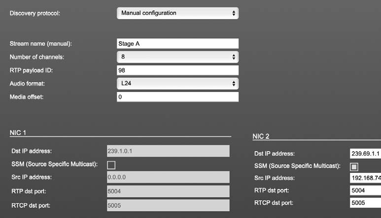
| Stream name (manual) | Stream name for display in status view and matrix. Can be specified individually, different than the name gathered from the SDP. |
| Number of channels | Number of audio channels in the stream |
| RTP-Payload-ID | RTP-Payload-ID of the audio stream (Real-Time Transport Protocol). Describes the format of the transported content. |
| Audio Format | Stream’s audio format (L16 / L24 / L32 / AM824) |
| Media Offset | Offset between stream’s timestamp and PTP-clock |
| Dst IP address | Multicast IP address of audio stream |
| SSM | Activate Source Specific Multicast filter for this stream.* |
| Src IP address | IP address of sending device.* |
| RTP dst port | Stream’s destination port for RTP |
| RTCP dst port | Stream’s destination port for RTCP (Real-Time Control Protocol) |
* An RTP packet contains the IP address of the sender (source IP) and the stream’s multicast address (destination IP). With SSM activated the receiver only accepts RTP packets of a certain destination IP that are originated by a sender with the specified source IP.
NOTE
RTP Payload ID must match between sender and receiver.
Status – Output Streams
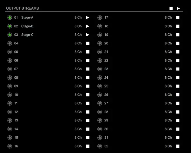 The device can send up to 32 streams. The overview displays the basic information of each stream.
| 01 to 32 | State of outgoing streams
|
| 01 to 32 Name | Name of stream defined in the settings |
| 01 to 32 xx ch | Number of audio channels transported by the stream |
| 01 to 32
|
Activate or deactivate stream.
|
| OUTPUT STREAMS
|
Click to activate or deactivate all streams.
|
Hyperlinks:
- Name (p 22)
Mouse over:
- LED – indicating stream state
TIP
AES67 Streams
To create output streams for interoperability in AES67 environments please consult the information document Info – AES67 Streams.
TIP
SMPTE 2110-30 / -31 Streams
To create output streams for interoperability in SMPTE ST 2110 environments please consult the information document Info – ST2110-30 Streams.
Both documents are available at http://academy.directout.eu.
Output Stream Settings
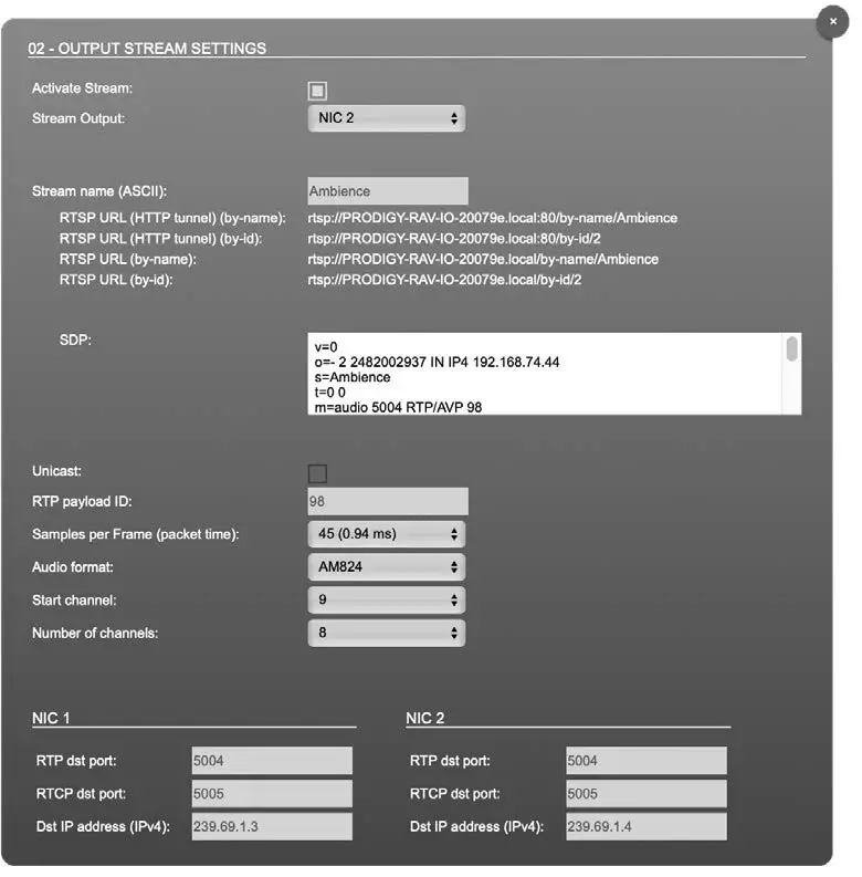 Up to 32 output streams can be sent to the network. Each stream is organized in a session (SDP = Session Description Protocol) that describes the stream parameters (audio channels, audio format, etc.).
Each stream may be labelled with an individual stream name (ASCII) which is useful for enhanced comfort at organizing the setup.
The stream settings allow to adjust the processing of the sent audio data (blocks per frame, format, signal routing, …). The sending of stream data starts once the stream has been enabled.
Once the stream is active, the SDP data is displayed and may be copied from the window or downloaded via http://<rav-io>/sdp.html?ID=<streamno.>.
| Activate stream | Stores parameters and activates or deactivates the receiving of audio data. (Unicast: additionally the negotiation of the connection) |
| Stream Output | Selects one or both NICs used for stream output. Both NICs means output redundancy. |
| Stream name (ASCII) | Individually defined name of an output stream. It is used in the URL which is indicated in different ways below.* |
| RTSP URL (HTTP tunnel) (by-name) / (by id) | Current used RTSP-URL of stream with HTTP port used for RTSP, stream name or stream id. |
| RTSP URL
(by-name) / (by id) |
Current used RTSP-URL of stream with stream name or stream id. |
| SDP | SDP data of the active stream. |
| Unicast | If activated, the stream is sent in unicast mode.** |
| RTP payload ID | Stream‘s payload id |
| Samples per Frame | Number of blocks containing payload (audio) per ethernet frame – see packet time on p 14. |
| Audio format | Stream’s audio format (L16 / L24 / L32 / AM824) *** |
| Start channel | Assignment of first stream channel from the audio matrix. E.g. stream with eight channels, starting at channel 3 is fed from channel 3 to 10 of the routing matrix. |
| Number of channels | Number of audio channels in the stream. |
| RTP dst port | Stream’s destination port for RTP |
| RTCP dst port | Stream’s destination port for RTCP (Real-Time Control Protocol) |
| Dst IP address (IPv4) | Stream’s IP address for multicast (should be unique for each stream). |
- Only ASCII characters are allowed.
- A unicast stream can only be received by one device. If a device is already receiving the stream, further connection calls by other clients are answered with ‚service unavailable‘ (503). The release time after disconnect or interruption of the client’s connection amounts to about 2 minutes.
- L16 = 16 bit audio / L24 = 24 bit audio / L32 = 32 bit audio / AM824 = standardized according to IEC 61883, allows AES3 transparent transmission (SMPTE ST 2110-31).
Advanced – Overview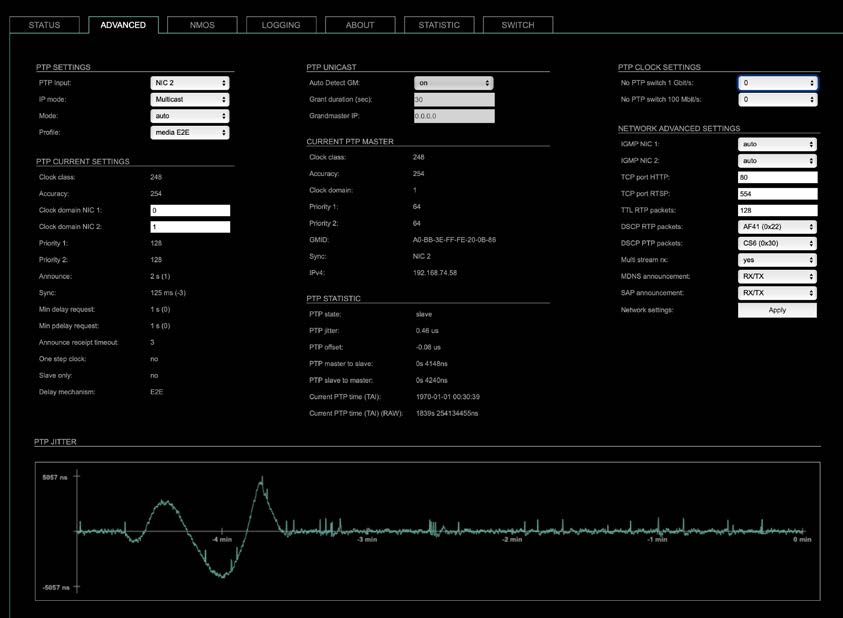
The tab ‘ADVANCED’ is divided into several sections:
- PTP SETTINGS – definition of PTP source, mode and profile
- PTP PROFILE CURRENT SETTINGS – definition of a customized PTP profile
- CURRENT PTP MASTER – monitoring PTP characteristics
- PTP STATISTIC – monitoring device’s PTP state, jitter and delay
- PTP CLOCK SETTINGS – definition of adaption algorithms to reduce jitter
- NETWORK ADVANCED SETTINGS – definition of network and QoS characteristics
- PTP JITTER – graphical display of measured PTP jitter
Advanced – PTP Settings
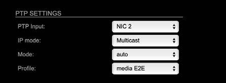
| PTP Input | Selects one or both network ports used for PTP input. Both ports means input redundancy. * |
| IP Mode | Multicast = Sync messages and delay request are sent as multicast message to every node within the network.
Hybrid = Sync messages are sent as multicast, delay requests are sent as unicast messages directly to the Grandmaster or Boundary Clock.** Unicast = Sync messages are sent as unicast, delay requests are sent as unicast messages directly to the Grandmaster or Boundary Clock.*** |
* Using redundant PTP-operation a switch-over is triggered not only at signal loss of the Grandmaster but depends on the quality of the PTP clock. Changes (e.g. clock class) are observed permanently and the algorithm decides for the best signal present.
** Hybrid Mode reduces the workload for all nodes in the network as they do not receive the (unnecessary) delay requests from other devices anymore.
*** Unicast Mode may help when multicast routing is not possible within the network. As an opposite to the Hybrid Mode it increases the workload of the grandmaster since sync messages must be sent to each single slave individually.

| Mode | auto = PTP-clock master / slave configuration is auto negotiated between devices in the network. Module’s master / slave state may change automatically.
slave only = PTP-clock slave configuration is preferred. Module clocks to another device in the network preferred master = PTP-clock master configuration is preferred. Module acts as network grandmaster. Priority values are adjusted automatically to ensure Grandmaster status. * master only = PTP-clock master is forced. ** |
| Profile | Selects predefined PTP profile (default E2E, default P2P, media E2E, media P2P) or activates customized PTP profile. |
* If more than one device announces as PTP-clock master the network Grandmaster is determined following the Best Master Clock Algorithm (BMCA).
** ‘Master only’ configures the device to act as Unicast Grandmaster. This setting is available only with PTP Mode set to ‘unicast’
NOTE
PTP profile ‚customized‘ allows for individual adjustment of the PTP parameters. If profile is set to ‚media‘ or ‚default‘ the PTP parameters cannot be altered and are displayed only. Factory default setting is PTP Media Profile E2E.
Advanced – PTP Unicast
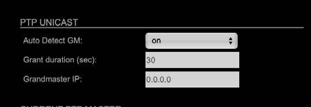
| Auto Detect GM | on = enables the automatic detection of the grandmaster * off = IP address of grandmaster needs to be defined
manually |
| Grant duration (sec) | Time period during which the slave receives sync messages from the grandmaster.** |
| Grandmaster IP | IP address of the grandmaster. *** |
* ‘Auto Detect GM’ is a proprietary function and might not be supported by 3rd party GMs.
** Depending on the temporary workload of the grandmaster the negotiation may fail.
*** This value is used only with ‘Auto Detect GM’ set to <off>.
About PTP Unicast
Since the BMCA is not available with PTP unicast, the PTP properties of the devices require some extra configuration.
Example:
| Grandmaster | IP Mode Unicast, Mode Master only |
| Slave(s) | IP Mode Unicast, Mode Slave Only,
Auto Detect GM ON, Grant Duration 30 sec |
Advanced – PTP Profile Customized Settings
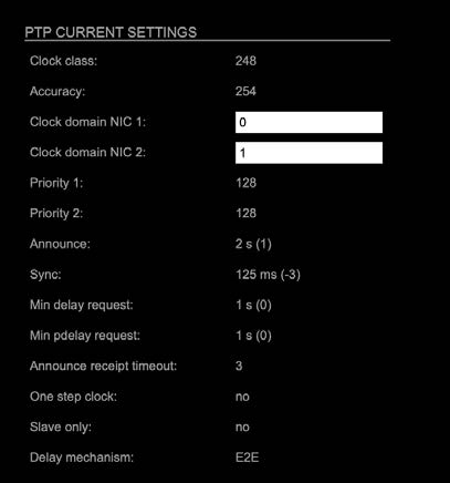 The settings become available with PTP profile set to ‘customized’.
| Clock class | PTP-clock’s class according to IEEE 1588 [read only] |
| Accuracy | PTP-clock’s accuracy according to IEEE 1588 [read only] |
| Clock domain NIC 1 | PTP-clock’s domain at NIC 1 |
| Clock domain NIC 2 | PTP-clock’s domain at NIC 2 |
| Priority 1 | Priority setting for master announcement (the smaller the value the higher the priority) |
| Priority 2 | If value ‘Priority1’ (and other PTP-clock parameters) of more than one device in the network match:
Priority setting for master announcement (the smaller the value the higher the priority) |
| Announce | Intervall of sending announce-packets for auto- negotiation. |
| Sync | Intervall of sending sync-packets to the PTP-clock slaves in the network. |
| Min delay request | Intervall of sending End-To-End packets of PTP-clock slave to PTP-clock master. To determine the offset slave-to-master. |
| Min pdelay request | Intervall of sending Peer-To-Peer packets between two PTP-clocks. To determine the offset master-to- slave and slave-to-master. |
| Announce receipt timeout | Number of missed announce-packets (threshold) to reinitialize the negotiation of PTP-clock master. |
| One step clock | Timestamp of PTP-clock is integrated in PTP-sync- packets. No follow-up packets are sent.
No = Two step clock is used |
| Slave only | Yes = PTP-clock is always slave. |
| Delay mechanism | E2E – Offset slave-to-master is determined by End-To- End packets.
P2P – Offset master-to-slave and slave-to-master is determined by Peer-To-Peer packets. |
Advanced – Current PTP Master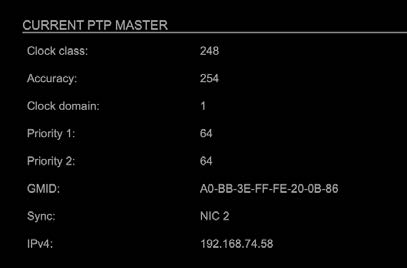 Monitoring display only.
| Clock class | PTP-clock’s class according to IEEE 1588 |
| Accuracy | PTP-clock’s accuracy according to IEEE 1588 |
| Clock domain | PTP-clock’s domain at selected NIC |
| Priority 1 | Priority setting for master announcement (the smaller the value the higher the priority) |
| Priority 2 | If value ‘Priority1’ (and other PTP-clock parameters) of more than one device in the network match:
Priority setting for master announcement (the smaller the value the higher the priority) |
| GMID | ID of current Grandmaster |
| Sync | Selected NIC for PTP clock |
| IPv4 | IP address of Grandmaster |
Advanced – PTP Statistic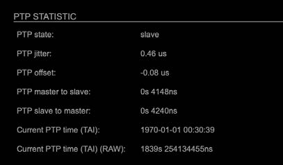 Monitoring display only.
| PTP state | Information about current PTP-clock state: intialize
error deactivated receiving data pre master master passive not calibrated slave |
| PTP jitter | PTP-clock jitter in microseconds (µs) |
| PTP offset | Offset relative to PTP-clock master |
| PTP master to slave | Absolute offset master-to-slave in nanoseconds |
| PTP slave to master | Absolute offset slave-to-master in nanoseconds |
| Current PTP time (TAI): | Date and time information from GPS source* |
| Current PTP time (TAI) (RAW): | RAW TAI from GPS source* |
* Temps Atomique International – if no GPS source is available for PTP time- stamping,the date / time display starts at 1970-01-01 / 00:00:00 after every reboot of the device.
Advanced – PTP Clock Setting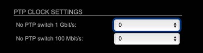
| No PTP Switch 1 Gbit/s | Adapted PTP-clock algorithm to reduce clock jitter using 1 GB network switches without PTP support.
Max. number of 1 Gbit/s switches: less than 10 |
| No PTP Switch 100 Mbit/s | Adapted PTP-clock algorithm to reduce clock jitter using 100 MB network switches without PTP support.
Max. number of 100 Mbit/s switches: 1 |
Advanced – Network Advanced Settings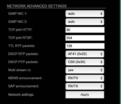
| IGMP NIC 1 | Definition or auto-select of IGMP version used to connect to a multicast router at NIC 1. |
| IGMP NIC 2 | Definition or auto-select of IGMP version used to connect to a multicast router at NIC 2 |
| TCP port HTTP | TCP port for HTTP |
| TCP port RTSP | TCP port for RTSP |
| TTL RTP packets | Time-To-Live of RTP packets – default: 128 |
| DSCP RTP packets | DSCP marking of QoS of RTP packets – default: AF41 |
| DSCP PTP packets | DSCP marking for QoS of PTP packets – default: CS6* |
| Multi stream rx | If activated, the device allows to subscribe to the same multicast stream more than one time – default: off |
| MDNS
announcement |
Announcement of streams via MDNS can be controlled to optimize network traffic or CPU load.
Values: Off, RX, TX or RX/TX ** |
| SAP announcement | Announcement of streams via SAP can be controlled to optimize network traffic or CPU load.
Values: Off, RX , TX or RX/TX ** |
| Network settings Apply | Confirms and saves changes being made. Reboot required. |
* AES67 specifies EF, but some implementations use EF for Audio streaming. To avoid overlapping of RTP and PTP packets in the same queue CS6 has been chosen as default.
** RX = receive, TX = transmit, RX/TX = receive and transmit
NOTE
Source-Specific Multicast (SSM) support for IGMP v3, v2 and v1 (SSM via protocol only in IGMP v3, SSM via internal filtering is applied for IGMP v2 and v1) – see “Source Specific Multicast” on page 19.
Advanced – PTP Jitter
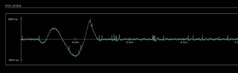 Graphical display of measured PTP jitter.
NOTE
An error message next to Jitter measurement is displayed if delay requests are not being answered by Grandmaster.
NMOS – Overview
 NMOS provides a family of specifications related to networked media for professional applications. It is produced by the Advanced Media Workflow Association (AMWA).
Support for NMOS is introduced with the AoIP Module version SW 0.17 / HW 0.46 according to the specifications:
- IS-04 Discovery & Registration
- IS-05 Device Connection Management
IS-04 allows control and monitoring applications to find the resources on a network. Resources include Nodes, Devices, Senders, Receivers, Sources, Flows…
IS-05 provides a transport-independent way of connecting Media Nodes.
More information: https://specs.amwa.tv/nmos/
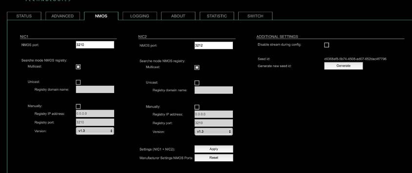
NMOS port – NIC1 & NIC2
The port entries for NIC1 and NIC2 are pre-configured by default. Modifications are possible but not necessary.

| NMOS port (NIC1 + NIC2) | Port address. Reboot required after modification. |
Search mode NMOS registry
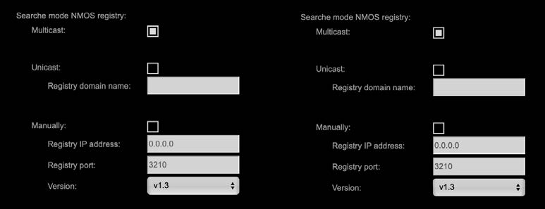
| Multicast | use mDNS to determine and connect to the registry server |
| Unicast | use DNS-SD to connect to the registry server |
| Registry domain name | DNS resolvable domain name of the registry server |
| Manually | |
| Registry IP address | |
| Registry port | |
| Version | Support of NMOS API version |
NMOS – Additional Settings
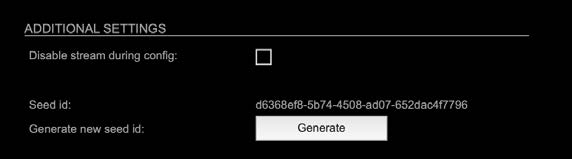
| Disable stream during config | Automatically disable and re-enable streams when settings are changed via NMOS (recommended) |
| Seed id | Unique identifier, subordered entities are derived from the seed id. |
| Generate new seed id Generate | Generates a new unique identifier. Reboot required. |
NMOS uses a logical data model based on the JT-NM Reference Architecture to add identity, relationships and time-based information to content and broadcast equipment. Hierarchical relationships group related entities, with each entity having its own identifier.
The identifiers are persistent across restarts of the device in order to make them useful over a period of time longer than a single production deployment.
New identifiers may be generated manually if required.
Logging
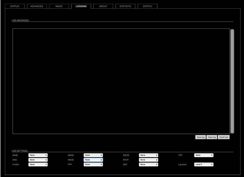 The tab ‘LOGGING’ displays logging depending on the ‘Log Settings’. The logging can be enabled individually for different protocols, each of with an adjustable filter. An adjustable log level specifies the information detail of each entry.
To save a log the content of the view can be copied and pasted to a text document.
Log Level
| 0 | log data |
| 1 | level and log data |
| 2 | protocol, level and log data |
| 3 | protocol, process-id of requesting process, process-id of running process, level and log data |
| 4 | protocol, process-id of requesting process, process-id of running process, level, processor time in ticks and log data |
| 5 | protocol, process-id of requesting process, process-id of running process, level, processor time in ticks, file name and line and log data |
Protocol Types
| ARP | Address Resolution Protocol |
| BASE | Basic operation of module |
| DHCP | Dynamic Host Configuration Protocol |
| DNS | Domain Name System |
| FLASH | Process for updating the module |
| IGMP | Internet Group Management Protocol |
| MDNS | Multicast Domain Name System |
| NMOS | Network Media Open Specification |
| PTP | Precision Time Protocol |
| RS232 | Serial Protocol |
| RTCP | Real Time Control Protocol |
| SAP | Session Announcement Protocol |
| TCP | Transmission Control Protocol |
| Zeroconf | Zero Configuration Protocol |
Log Filter
| NONE | logging disabled |
| ERROR | error occurred |
| WARNING | warnings- condition that may lead to unwanted behavior or an error |
| INFO 1 | log info* + warning + error |
| INFO 2 | log info* + warning + error |
| INFO 3 | log info* + warning + error |
| INFO 4 | log info* + warning + error |
* increasing amount of log info starting from ‚INFO 1‘
Log Operation
| Save log | Downloads the current log entries to a text-file (log.txt). |
| Clear log | Deletes all log entries without further prompt. |
| Scroll lock | Interrupts automatic scrolling of the list view to allow copying the content to a text file via copy & paste. If scrolling is stopped for a longer period of time the display may not list all entries. |
Statistic
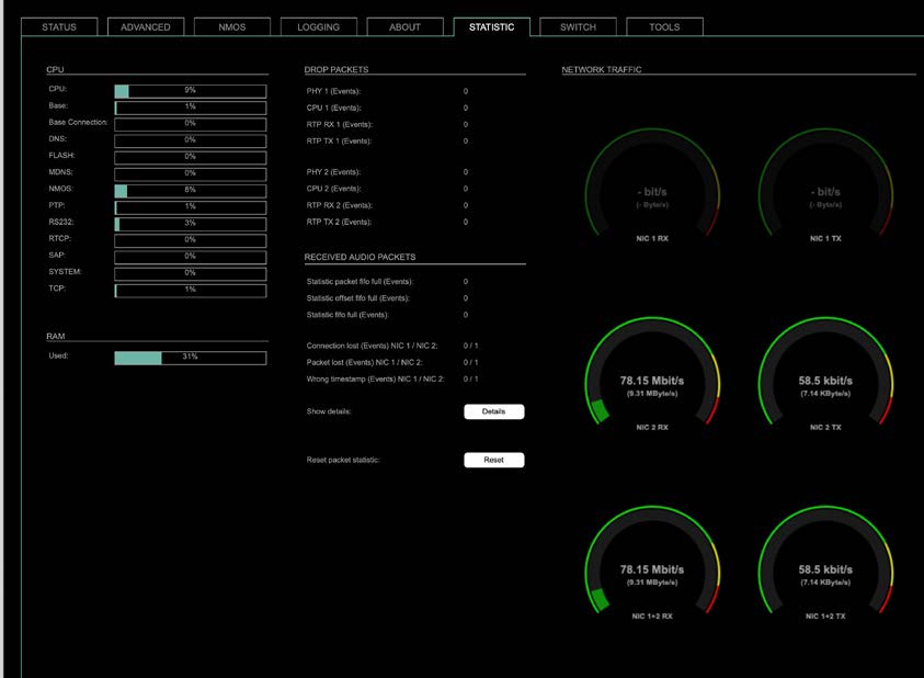 The tab ‘STATISTIC’ displays an overview of the CPU load of the particular processes, an error counter and a monitor display to indicate the incoming (RX) and outgoing (TX) network traffic on both network ports individually.
| Details | Displays a list of input streams and related events (connection lost, packet lost, wrong timestamp) of received audio packets. |
| Reset | Resets the packet statistic |
See “Protocol Types”
Switch
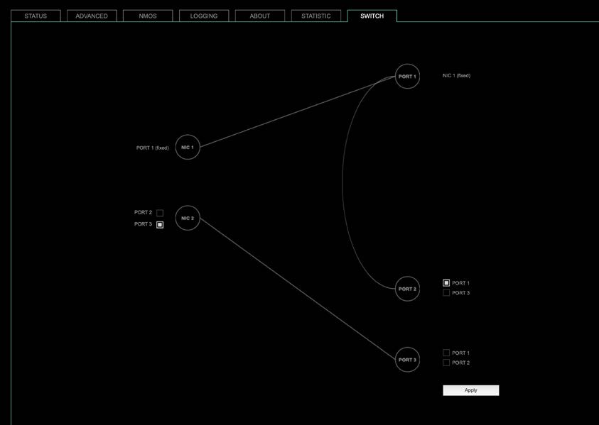 Two independent network interfaces (NICs) can be configured in the switch configuration.
- Port 1 is fixed assigned to NIC 1.
The other ports can be assigned to either NIC 1 or NIC 2
NOTE
If you want to use a port that is not assigned to a NIC e.g. to patch the device‘s management port (MGMT) into the audio network, you can link it to one of the audio ports.
NOTE
To access the module‘s control page it is required to connect the management network to one of the ports that is directly attached to a NIC – see next page.
To give the very best PTP synchronisation performance, the switch incorporates advanced timestamping between the external PORTS and the internal NICs. As a consequence, the on-board switch cannot be used to connect other PTP devices via a single shared connection to the wider network.
Please connect all other PTP devices directly to your system’s network switch.
Tools
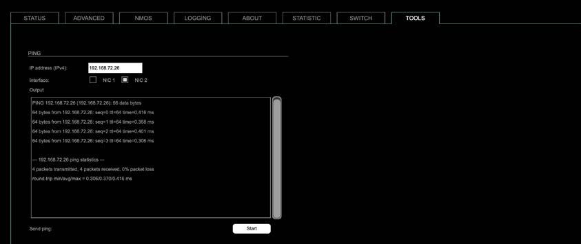 The tab ‘TOOLS’ offers a generator to ping any IP address (IPv4) from either NIC 1 or NIC 2. The result is displayed at the ‘Output’.
| IP address (IPv4) | Enter IP address (IPv4) to be pinged |
| Interface | Select NIC 1 or NIC 2 |
| Start | Sends ping to the specified IP address from selected NIC. |
RAV2 – Firmware Update
The RAV2 module is updated via network.
Open the control page of the module and navigate to the tab STATUS and click SETTINGS in the top right corner (p 8).
 Click ‘Update’ and browse to the update file after unzipping first. Example: rav_io_hw_0_29_sw_0_94.update
Folllow the instructions displayed.
WARNING!
It is strongly recommended to backup the device configuration (Save Preset) before running any update.
Documents / Resources
 |
DirectOut RAV2 Module Audio Network Module [pdf] User Manual RAV2 Module Audio Network Module, RAV2, Module Audio Network Module, Audio Network Module, Network Module |