DIODES AL58263 16 Channel LED Driver with 16 Bit APDM Control
General Description
- The AL58263 is a 16-channel constant-current LED driver with 16-bit grayscale Adaptive Pulse Density Modulation (APDM) and supports error diagnostics, power-saving functionality, and current gain control.
- This distinctive APDM technology abates the non-ideal IOUT distortion due to non-symmetric transient responses and enhances the refresh rate by efficiently separating the frame waveform.
- The device operates over a 3.3V to 5V input voltage range (±10%), fast 30MHz DCK input, and provides 16 open-drain constant-current sinking outputs that are rated to 15V and deliver up to 55mA of high-accuracy current to each LED string.
- The current at each output is programmable by an external current-sensing resistor and can be adjusted by a 6-bit global current control.
- The AL58263 also supports compulsory error detection, where the display image will not be affected as the intervals and currents are small.
- Differing from error mode selections; the specified diagnostic can be performed. Errors will be stored in the shift register and can be read out from the DO pin.
- Moreover, the threshold voltage for LED short detection can be selected to comply with different LED string configurations. Sleep mode can also efficiently lower the supply current in power-saving applications.
- The AL58263 is available in the TSSOP-24EP package and is specified over the -40°C to +85°C ambient temperature range.
Applications
- Indoor and outdoor LED video displays
- Variable message signs (VMS)
- Dot matrix modules
- LCD backlighting
Key Features
- 3.3~5V operating supply voltage (±10%)
- 2~55mA/5V, 2~35mA/3.3V output current range
- 15V-rated output channels for long LED strings
- ±1.5% (typ.) LED current accuracy between channels
- ±3% (typ.) LED current accuracy between chips
- ±0.1% output current regulation capability
- 16-bit grayscale resolution with Adaptive Pulse Density Modulation (APDM) control
- Non-scramble waveform for high-power LED applications
- Grayscale counter reset selection
- Grayscale data synchronization selection
- 6-bit global current control: from 12.5% to 200%
- Compulsory error detection includes LED open, LED short output port leakage, output short-to-GND, output short-to-power, and REXT short-to-GND
- Compulsory error detection with 0.1mA
- Short detection threshold voltage selection (2/3/4/4.5V)
- Sleep mode to lower the supply current to 10μA (typ.)
- Overtemperature warning
- 30MHz Clock frequency for data transfer
- EMI reduction grayscale clock
- External GCK watchdog
- 8KV ESD protection on current output pins
- Totally Lead-Free & Fully RoHS Compliant (Notes 1 & 2)
- Halogen and Antimony Free. “Green” Device (Note 3)
- An automotive-compliant part is available under a separate datasheet (AL58263Q).
Notes
- No purposely added lead. Fully EU Directive 2002/95/EC (RoHS), 2011/65/EU (RoHS 2) & 2015/863/EU (RoHS 3) compliant.
- See https://www.diodes.com/quality/lead-free/ for more information about Diodes Incorporated’s definitions of Halogen- and Antimony-free, “Green” and Lead-free.
- Halogen- and Antimony-free “Green” products are defined as those which contain <900ppm bromine, <900ppm chlorine (<1500ppm total Br + Cl) and <1000ppm antimony compounds.
Hardware Description
The AL58263EV1 evaluation board is shown in Figure 1 and Figure 2.
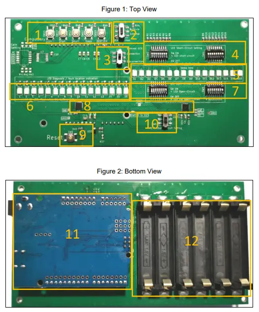
| Section | Description |
| 1 | Mode select button |
| 2 | GCK internal/external select switch |
| 3 | GCK external connect switch |
| 4 | LED short circuit setting switch (default OFF) |
| 5 | LED scrolling mode display section |
| 6 | LED diagnosis/fault location section |
| 7 | LED open-circuit setting switch (default ON) |
| 8 | AL58263 16-channel LED driver |
| 9 | System reset button |
| 10 | REXT short circuit setting switch (default OFF) |
| 11 | Control board |
| 12 | AAA dry battery box |
Power Supply Options
The device features two power supply options:
- Utilizing six AAA dry batteries for portable convenience.
- Connecting the ARDUINO control board via the USB interface (type C) to serve as the power source.
Note: The two power supply methods cannot be used simultaneously
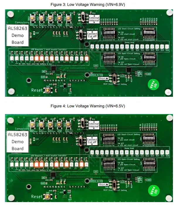
Low Voltage Warning
In the event of insufficient voltage from the connected batteries (total voltage in series ranging from 6V to 7V), the “LED Fault Location (Status) Display Area” will present the BCD code of the total series voltage. This BCD code includes the tens digits of the voltage (LED1-4), the units digit of the voltage (LED5-8), the first decimal digit of the voltage (LED9-12), and the second decimal digit of the voltage (LED13-16).
Quick Start Guide
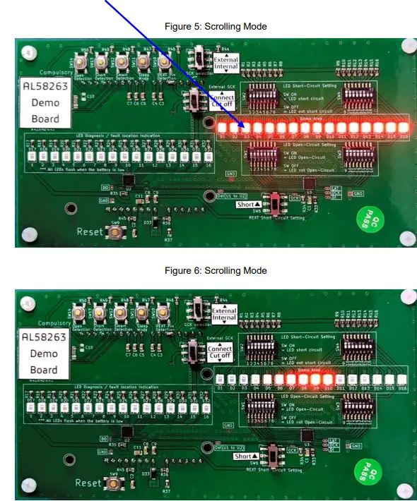
Scrolling Mode
- Activate Scrolling Mode by connecting the batteries, plugging in the ARDUINO control board to the USB interface for power, or pressing the Reset button.
- Scrolling Mode showcases LEDs (D1~D16) gradually brightening and dimming in the “Demo Area” LED section.
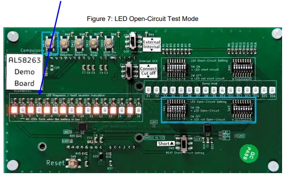
LED Open-Circuit Detection Mode
- Enter LED Open Circuit Detection Mode during Scrolling Mode by long-pressing SW14 for over 1 second.
- Set a specific LED as an open circuit by toggling the “LED Open Circuit Setting SW1/SW3” to the OFF position; the corresponding LED lights up in the “LED Diagnosis / Fault Location Indication” LED section
- Press and hold SW14 for more than 1 second to return to Scrolling Mode.
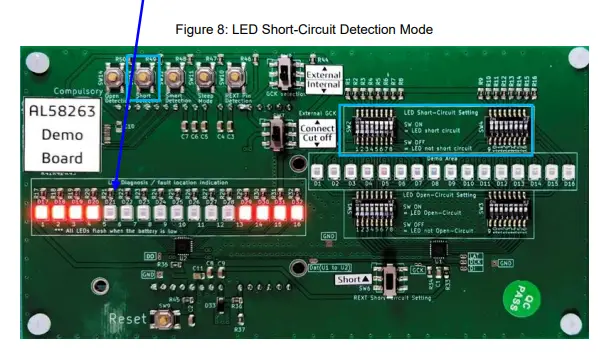
LED Short-Circuit Detection Mode
- Enter LED Short Circuit Detection Mode during Scrolling Mode by long-pressing SW13 for over 1 second.
- Set a specific LED as a short circuit by toggling the “LED short Circuit Setting SW2/SW4” to the ON position; the corresponding LED lights up in the “LED Diagnosis / Fault Location Indication” LED section.
- Press and hold SW13 for more than 1 second to return to Scrolling Mode.
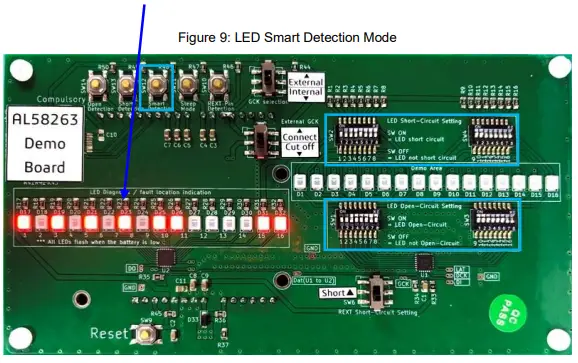
LED Smart Detection Mode
- Enter LED Smart Detection Mode during Scrolling Mode by long-pressing SW12 for over 1 second.
- Set a specific LED as an open circuit by toggling the “LED Open Circuit Setting SW1/SW3” to the OFF position or as a short circuit by toggling the “LED short Circuit Setting SW2/ SW4” to the ON position; the corresponding LED lights up in the “LED Diagnosis / Fault Location Indication” LED section.
- Press and hold SW12 for more than 1 second to return to Scrolling Mode.
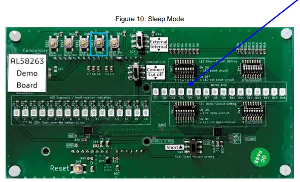
Sleep Mode
- Enter Sleep Mode during Scrolling Mode by long-pressing SW11 for over 1 second. All 16 LEDs turn off in the “Demo Area”.
- Press and hold SW11 for more than 1 second to return to Scrolling Mode.
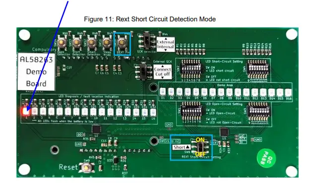
 Rext Short-Circuit Detection Mode
- Enter Rext Short Circuit Detection Mode by long-pressing SW10 for over 1 second.
- Toggle the “Rext Short to Ground Setting Switch” to ON to set Rext Short to Ground.
- When Rext is shorted to ground, LED 1 will flicker at a one-second frequency in the “LED Diagnosis / Fault Location Indication” LED section.
- Press and hold SW10 for more than 1 second to return to Scrolling Mode
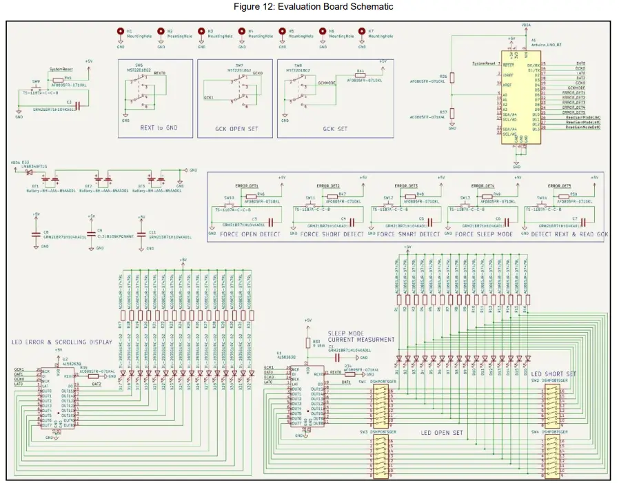
Evaluation Board Schematic
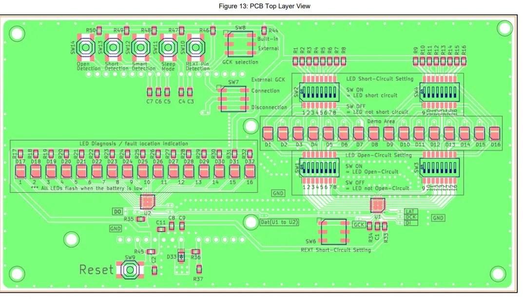
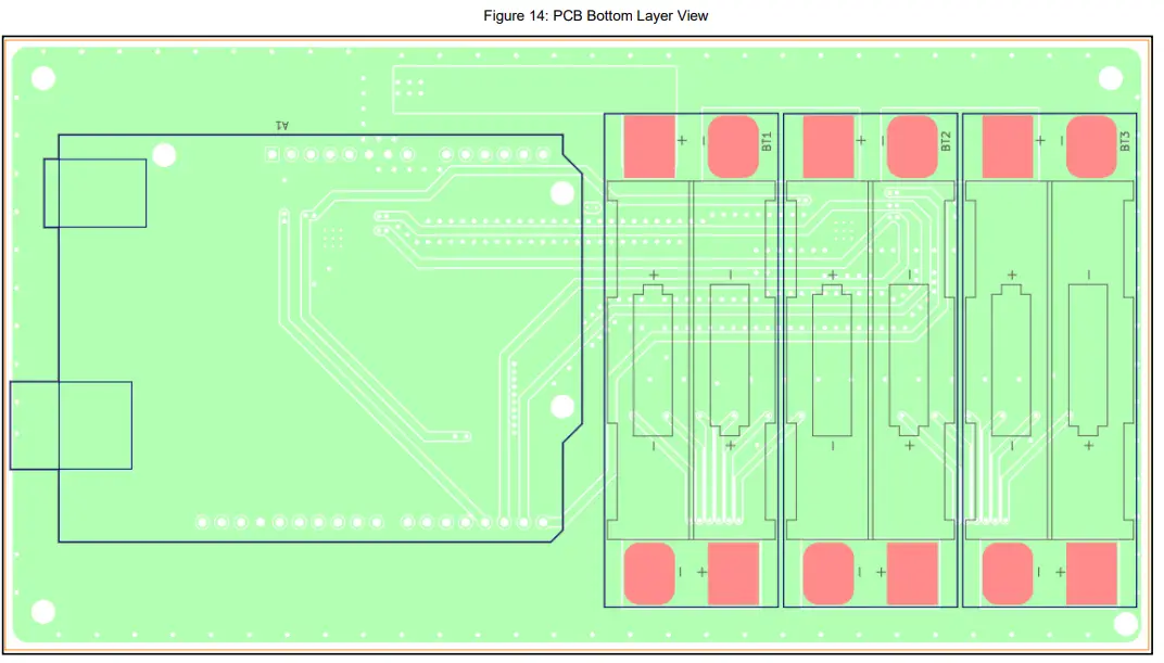
Evaluation Board Layout
Bill of Materials
| Ref. | Description | Manufacturer | Part Number | Package |
| U1, U2 | 16-Channel LED Driver with 16-Bit APDM Control | Diodes Incorporated | AL58263Q | TSSOP-24EP |
| BT1, BT2, BT3 | Battery Holder | MYOUNG | BH-AAA-B5AA001 | – |
| C9 | Capacitor SMD, 10uF/10V X7R | Samsung Electro- Mechanics | CL21B106KPQNNNE | 0805 |
| C1, C2, C3, C4, C5, C6, C7, C8, C11 | Capacitor SMD, 0.1uF/50V X7R | Murata | GRM21BR71H104KA01L | 0805 |
| D33 | Schottky Barrier Rectifiers:40VDC/IF=3A | Diodes Incorporated | B340AQ | SMA |
| D1 ~ D32 | Red LED SMD, Forward Current=40mA | XINGLIGHT | XL-2835SURC-02 | SMD2835 |
| R33 | Resistor SMD, 0 ohm 1 %, 1/8 W | YAGEO | AC0805FR-070RL | 0805 |
| R34, R35, R37 | Resistor SMD, 2k ohm 1 %, 1/8 W | YAGEO | AC0805FR-072KL | 0805 |
| R1~R32 | Resistor SMD, 47 ohm 1 %, 1/8 W | YAGEO | AC0805JR-0747RL | 0805 |
| R36, R38~R50 | Resistor SMD, 10k ohm 1 %, 1/8 W | YAGEO | AF0805FR-0710KL | 0805 |
| SW1~SW4 | Button Switch | KINGTEK | DSHP08TSGER | DIP-8 |
| SW5 | Button Switch | KINGTEK | DSHP06TS-S | DIP-6 |
| SW6~SW8 | Button Switch, SMD, SW_SPST_SKQG | SHOU HAN | MST22D18G2 | SMD 3.6×9.1 |
| SW9~SW14 | Button Switch | XKB Connection | TS-1187A-C-C-B | DIP-6 |
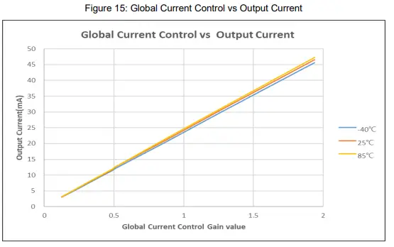
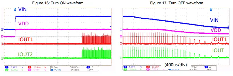
System Performance
- Global Current Control (VDD=5.5V)
- Turn ON/OFF Waveform
IMPORTANT NOTICE
- DIODES INCORPORATED (Diodes) AND ITS SUBSIDIARIES MAKE NO WARRANTY OF ANY KIND, EXPRESS OR IMPLIED, WITH REGARDS TO ANY INFORMATION CONTAINED IN THIS DOCUMENT, INCLUDING, BUT NOT LIMITED TO, THE IMPLIED WARRANTIES OF MERCHANTABILITY, FITNESS FOR A PARTICULAR PURPOSE OR NON-INFRINGEMENT OF THIRD PARTY INTELLECTUAL PROPERTY RIGHTS (AND THEIR EQUIVALENTS UNDER THE LAWS OF ANY JURISDICTION).
- The information contained herein is for informational purposes only and is provided only to illustrate the operation of Diodes’ products described herein and application examples. Diodes does not assume any liability arising out of the application or use of this document or any product described herein. This document is intended for skilled and technically trained engineering customers and users who design with Diodes’ products. Diodes’ products may be used to facilitate safety-related applications; however, in all instances, customers and users are responsible for (a) selecting the appropriate Diodes products for their applications, (b) evaluating the suitability of Diodes’ products for their intended applications, (c) ensuring their applications, which incorporate Diodes’ products, comply the applicable legal and regulatory requirements as well as safety and functional-safety related standards, and (d) ensuring they design with appropriate safeguards (including testing, validation, quality control techniques, redundancy, malfunction prevention, and appropriate treatment for aging degradation) to minimize the risks associated with their applications.
- Diodes assumes no liability for any application-related information, support, assistance, or feedback that may be provided by Diodes from time to time. Any customer or user of this document or products described herein will assume all risks and liabilities associated with such use and will hold Diodes and all companies whose products are represented herein or on Diodes’ websites, harmless against all damages and liabilities.
- Products described herein may be covered by one or more United States, international,l or foreign patents and pending patent applications. Product names and markings noted herein may also be covered by one or more United States, international, or foreign trademarks and trademark applications. Diodes does not convey any license under any of its intellectual property rights or the rights of any third parties (including third parties whose products and services may be described in this document or on Diodes’ website) under this document.
- Diodes’ products are provided subject to Diodes’ Standard Terms and Conditions of Sale (https://www.diodes.com/about/company/terms-and-conditions/terms-and-conditions-of-sales/) or other applicable terms. This document does not alter or expand the applicable warranties provided by Diodes. Diodes do not warrant or accept any liability whatsoever in respect of any products purchased through unauthorized sales channels.
- Diodes’ products and technology may not be used for or incorporated into any products or systems whose manufacture, use, or sale is prohibited under any applicable laws and regulations. Should customers or users use Diodes’ products in contravention of any applicable laws or regulations, or for any unintended or unauthorized application, customers and users will (a) be solely responsible for any damages, losses, or penalties arising in connection therewith or as a result thereof, and (b) indemnify and hold Diodes and its representatives and agents harmless against any and all claims, damages, expenses, and attorney fees arising out of, directly or indirectly, any claim relating to any noncompliance with the applicable laws and regulations, as well as any unintended or unauthorized application.
- While efforts have been made to ensure the information contained in this document is accurate, complete, and current, it may contain technical inaccuracies, omissions, and typographical errors. Diodes does not warrant that information contained in this document is error-free and Diodes is under no obligation to update or otherwise correct this information. Notwithstanding the foregoing, Diodes reserves the right to make modifications, enhancements, improvements, corrections, or other changes without further notice to this document and any product described herein. This document is written in English but may be translated into multiple languages for reference. Only the English version of this document is the final and determinative format released by Diodes.
- Any unauthorized copying, modification, distribution, transmission, display, or other use of this document (or any portion thereof) is prohibited. Diodes assumes no responsibility for any losses incurred by the customers or users or any third parties arising from any such unauthorized use.
- This Notice may be periodically updated with the most recent version available at https://www.diodes.com/about/company/terms-and-conditions/important-notice
The Diodes logo is a registered trademark of Diodes Incorporated in the United States and other countries. All other trademarks are the property of their respective owners.
© 2024 Diodes Incorporated. All Rights Reserved.
www.diodes.com
Documents / Resources
 |
DIODES AL58263 16 Channel LED Driver with 16 Bit APDM Control [pdf] User Guide AL58263, AL58263EV1, AL58263 16 Channel LED Driver with 16 Bit APDM Control, AL58263, 16 Channel LED Driver with 16 Bit APDM Control, 16 Bit APDM Control, APDM Control |


