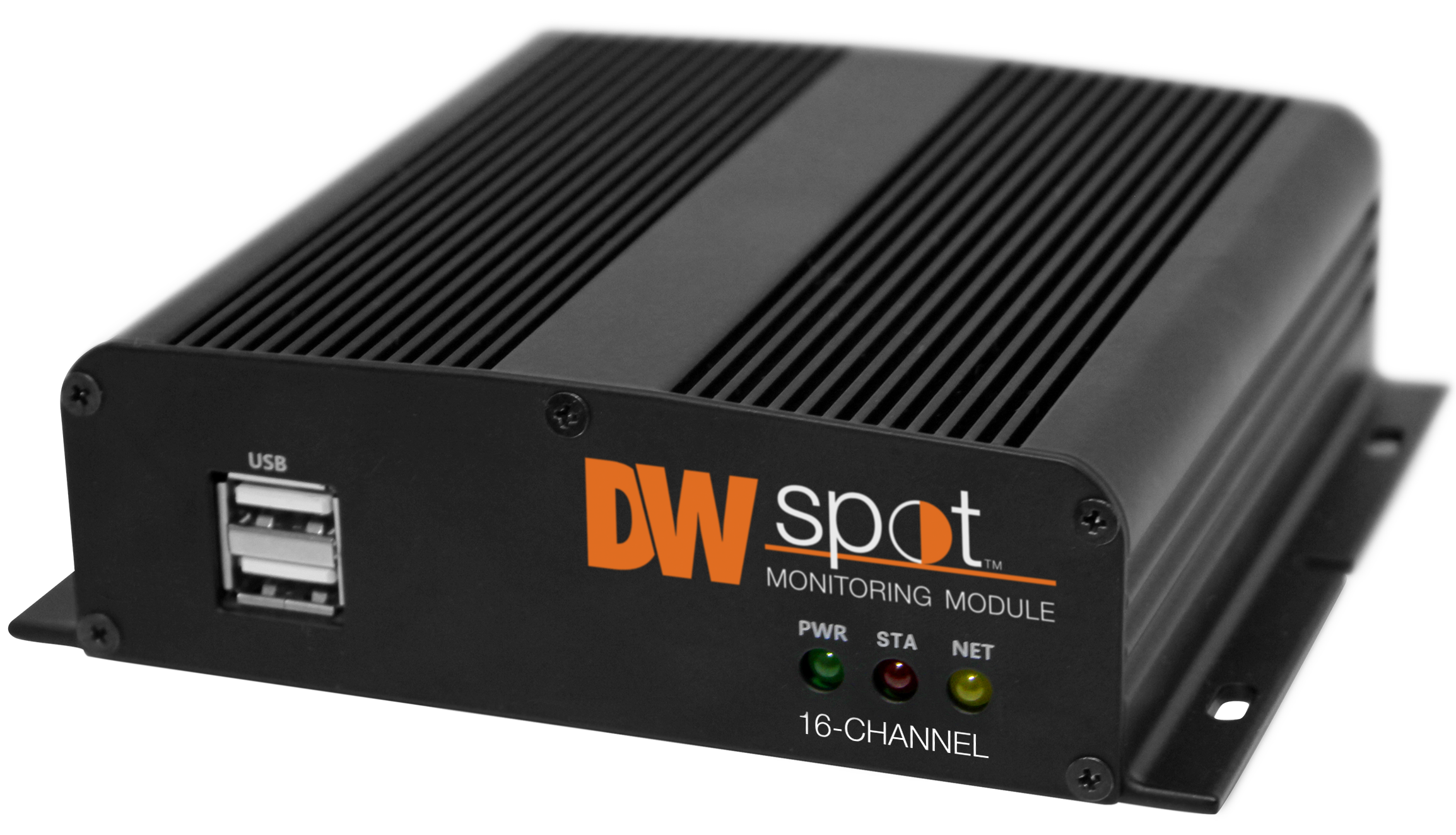
Digital Watchdog DW SpotTM Monitoring Module
INFO
Default login Information: admin | no password
When logging into the recorder for the first time, you will be prompted to setup a new password.
Before operating the system, please read and retain this user manual for future reference. The picture might differ according to the specification and model. Copyright © DW. All rights reserved. Specifications and pricing are subject to change without notice.
WARNING
TO REDUCE FIRE OR SHOCK HAZARD, DO NOT EXPOSE THE UNIT TO RAIN OR MOISTURE.
The installation should be made by a qualified service person and conformed to all local codes.
Cautions
Read Before System Operation
Follow these details to prevent material damage or personal injury. Signs of Caution and Warning
 Warning: This sign indicates that the user could die or be seriously wounded if not used or installed properly.
- Caution: This sign indicates that the user could be wounded or expect property damage if not used or installed properly.
- Warning: Do not expose the product to fog, rain, or too much humidity to decrease the danger from electric shock or fire.
General Warning Warning
- Use the power cord supplied or recommended by the supplier, or it may cause a fire.
- Do not disassemble or reassemble the product. It may cause malfunction or fire.
- Enquire to your vendor for repair. It may cause electric shock or fire if the repair is improper.
- Do not touch the product with wet hands. It may cause malfunction or electric shock.
- A professional must ensure product installation, or it may cause malfunction, electric shock, or fire.
- Ground applies to video products equipped with a 3-wire grounding type plug having a third (grounding) pin. This plug only fits into a grounding-type power outlet. If grounding is not done, it may cause malfunction or electric shock.
- A ground connection must not touch the gas, water, or telephone lines. If grounding is not done properly, it may cause electric shock.
- Prevent metallic foreign substances from going inside the product. It may cause malfunction or electric shock.
- Do not spray insecticide or flammable spray while driving. It may cause a fire.
- Place the system in an open place where air ventilation is guaranteed, or it may cause overheating and seriously damage the system to be fired.
- Prevent water from instilling inside electrical parts. Clean with a dry towel, or malfunction or electric shock could result.
Caution
- Use the power cord supplied or recommended by the supplier. The internal fan rotates at high speed and may cause an accident.
- Do not drop; give strong vibration or shock to the product. It may cause malfunction.
- The air inhaler of the front panel and air outlet of the back panel must not be blocked during installation.
The product’s internal temperature would be greater than allowable and could cause malfunction or fire. - Do not touch the product or the power cord when thunder strikes. It may cause an electric shock.
- Do not install the product near or on top of the heating source. The product’s internal temperature would be greater than allowable and could cause malfunction or fire.
- Do not install the product on an inclined or unstable location or where vibration could be committed. It may cause malfunction.
Cautions about the Power Warning
- Must use the grounding outlet to connect the power cord, or it may cause a fire.
- Do not connect in the middle of the power cord or use the extension cord. It may generate heat or cause a fire.
- Do not touch the power cord with wet hands. It may cause an electric shock.
- Keep the power cord dry and protect it from humidity. It may generate heat or cause a fire. The power cord is not waterproof.
- Hold the body of the plug while removing the power plug. Do not pull the power cord. Damage to the power cord may generate heat or cause a fire.
- Check the power plug regularly. Humidity and moderation in smoking may cause a fire.
- Remove the power cord from the outlet when the product is not used for a long time. It may cause a short-circuit or electric shock.
Caution
- Do not turn off the power by removal of the power plug.
To turn off the power, click the power button from the front panel.
When the system stops abnormally, the power button might not work. Click the power button for 5 full seconds to turn the power off. - Do not cut off the power artificially or give shock or vibration to the unit while the hard disk is activating. It may cause hard disk failure or loss of data.
Remarks
- Pictures and buttons are subject to be changed or modified up to different models.
- Function or configuration is subject to change or modification without prior notice for product improvement
Getting Started
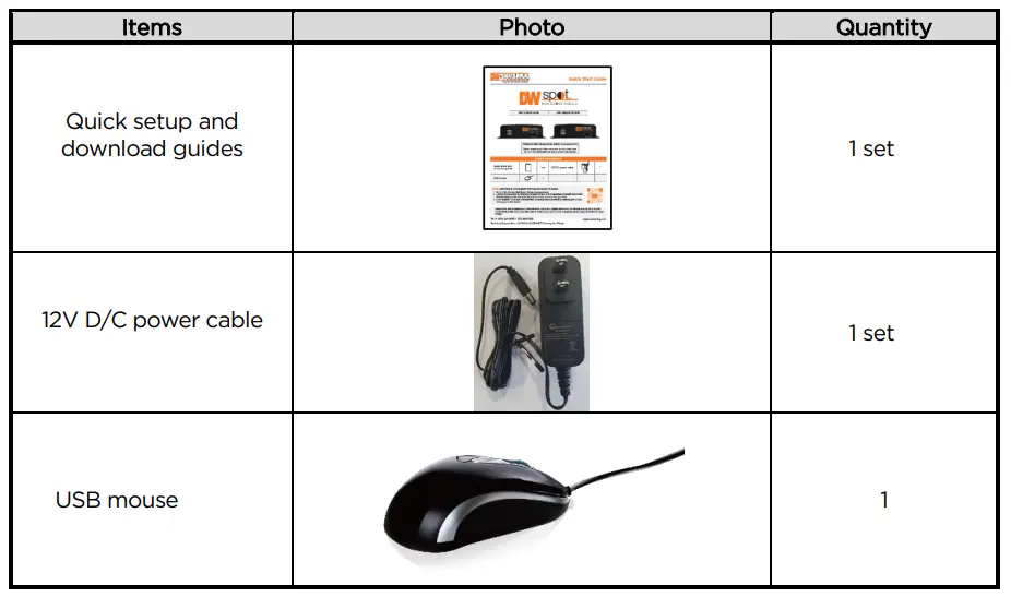
Checking Supplied Items
Make sure that you have the following items supplied with your module. If any items are missing or damaged, notify your vendor immediately. Keep the packing utilities for moving or storage purposes
System Startup
After connecting peripheral devices such as monitors and a mouse to the module, power up the module by connecting the DC12V adaptor/ power cable to the power jack on the rear panel. The boot logo will display. Please wait until the boot process completes.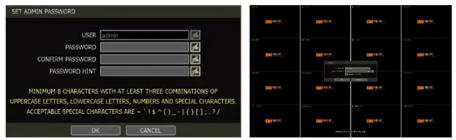
When the system is up, the password change window is displayed. The user must set the password to a minimum of 8 characters with at least 3 combinations of uppercase letters, lowercase letters, numbers and special characters. Acceptable special characters are 『~ ‘! $ ^ ( ) _ – | { } [ ] ; . ? /』. To log in, right-click anywhere on the screen and enter the username and password in the pop-up screen. There is only one Administrator Account configurable in the module. It is assigned with an unchangeable User ID marked as ‘admin.’ The administrator account has full access to the module and its configurable parameters, can create new users, and assigns rights to the new user accounts. The login process is unnecessary if the module is set as AUTO LOGON.
Caution
- It may take a few minutes to start up the system after turning on the power in case the user sets the network configuration to DHCP mode, but in the situation that there is no DHCP server in the network or the network is not connected,
- The mouse is included. Choosing well-known major brands such as Dell, Microsoft, LOGITECH, or Samsung is highly recommended if you need to replace it.
Note
- Contact DW’s technical support to reset your password.
- Refer to “Section 4.1.2 User” for AUTO LOGON and AUTO LOGOFF.
System Shutdown
To turn off the power, click the exit button [ ] on the toolbar, then select SHUTDOWN in the Exit screen
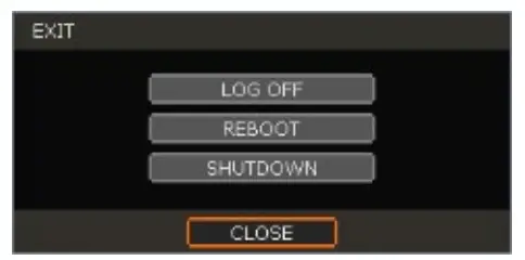
Input the password and click the OK button to shut down the system. Click the YES button to confirm shutdown.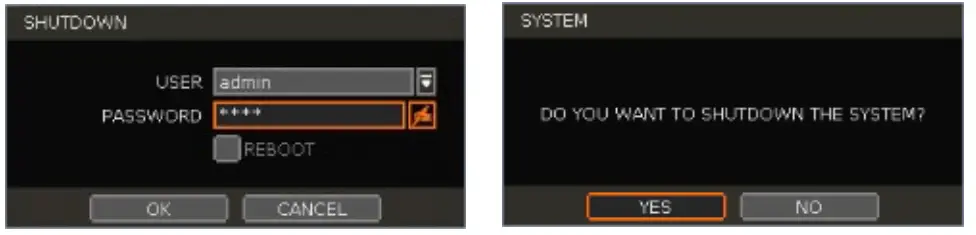
Note
Input passwords using the virtual keyboard.
System Overview
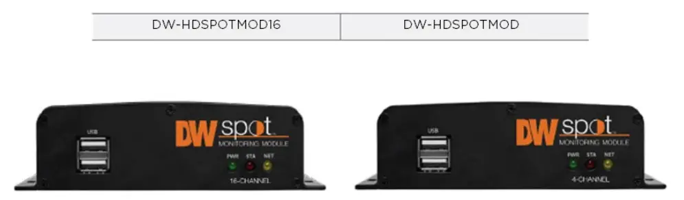
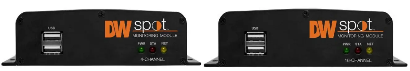
Front Panel
- USB Port: import and export settings and firmware upgrade for USB mouse.
- LED Indicator: Indicates system status. (Power and Network status)
Back Panel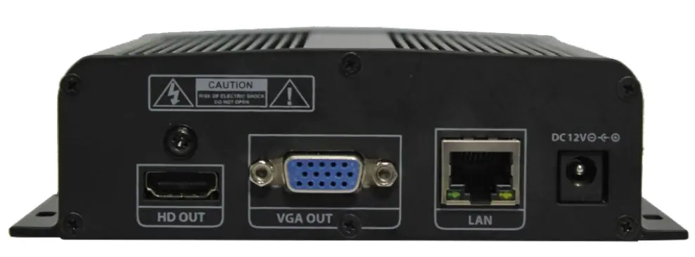
- HD out: Connect a true HD monitor to the unit (cables not included).
- VGA out: connect a VGA monitor to the unit (cables not included).
- LAN: Connect an RJ45 cable to the unit to connect it to the local network (cables not included).
- Power: Connect the 12V DC power cable to the unit and then to an adequate power supply.
Tool Bar
In live view, move the mouse cursor to the bottom of the screen to show the menu bar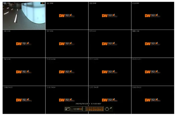
 Menu
Menu
Click on the menu button to access the module’s main menu screen. See “4. Setting” for details.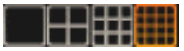 Display Mode
Select the display split mode from the available options. Select 1CH, 4CH, 9CH or 16CH mode. Sequence
Start/stop the sequence mode in live mode. The sequence is disabled if all channels are displayed.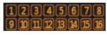 Channel
Switch to a single-channel view of a specific channel by pressing the corresponding number. Exit
Exit
Exit the module with three options: Log Off, Reboot and Shutdown. Pin
Pin
When selected, the menu bar will be fixed on the screen permanently, regardless of the mouse’s position.
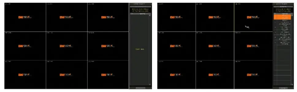
Startup Wizard
The STARTUP WIZARD will appear when the module is launched for the first time. This wizard helps users set up the module’s most basic settings for proper functioning. Users can access the Startup Wizard screen anytime by clicking the Startup Wizard button under the MENU>SYSTEM>SETTINGS menu. (See “4.1.5 SETTINGS”). If “DISPLAY ON SYSTEM STARTUP” is selected, the Startup Wizard will appear every time the system reboots.
Language
Select the language from the available drop-down options. Click APPLY to save the changes and NEXT to move to the next screen.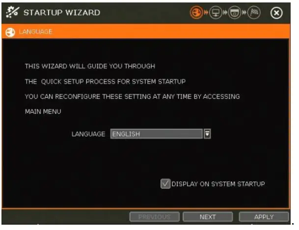
Network
Set up the module’s network settings for remote connection. 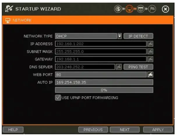
Network Type
DHCP: The module will automatically acquire all the network settings according to the current network requirements. Click the ‘IP DETECT’ button to fill out all the network settings automatically. Static IP: manually enter all the network settings. For proper configuration, it is recommended that the module be assigned a DHCP address and let it auto-discover all the appropriate network settings. Then, change the Network Type to Static IP and save the changes. Contact your Network Administrator for more information.
IP Address
If DHCP is selected, the IP address will automatically adjust to match the network’s requirements. Users may manually change the IP address as needed (Network Type must be set to Static).
Subnet Mask
The Subnet Mask address classifies the subnet to which the system belongs. Contact your Network Administrator for more information.
Gateway
This is the IP address of the router or gateway server. It is required when connecting to the module through the external router over the internet (from another network). Contact your Network Administrator for more information.
DNS Server
Enter the IP address of the Domain Name Server. Users should input the DNS Server information to use DDNS, E-mail notifications and NTP Server. Contact your Network Administrator for more information.
WEB Port
Input the port number to use when connecting from the Web Browser. The default is 80. Contact your Network Administrator for more information.
Auto IP
Displays the system’s IP address.
Use UPnP (Universal Plug and Play)
UPnP is a plug-and-play feature that allows the module to be automatically discovered by a PC on the same network. Go to “My Network” on your PC to locate the module. The computer will scan your network for all supported devices. The first five characters of the file name of a detected module represent the model number, followed by the module’s IP address.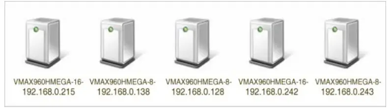
Once the PC discovers the module, double-click the icon to open the module’s web client. Enter your User ID and Password to log in and click ‘Connect.’
Camera Management
The Camera Management menu allows users to search, register and manage IP cameras, DVRs and NVRs. See “3.2 Camera Registration” for more information.
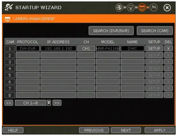
Search (DVR/NVR)
The module will scan the network for all supported DVR/NVR. Select the devices you wish to register from the search results and press the ‘GET INFO’ button. ‘DETAIL INFO’ lets users get more information on the device’s streams. Enter the user ID and password for the devices you are registering. Users can also select which channels to register. Click ‘APPLY’ to register the device.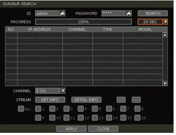
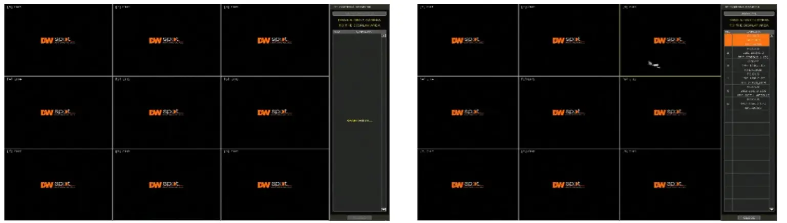
Search (CAM)
The module will scan the network for all supported IP cameras automatically. Users can drag cameras to the viewing channel and assign them to the channels based on the results.
- Click the START button to search the camera.
- Select a camera, and while clicking on the camera, drag it to a channel to assign it. Enter the user ID and password for the device you are registering if needed.
- Click the CLOSE button to finish the process.
Finish
Complete the setup by registering your product. When the setup wizard is completed, click the FINISH button to close the setup wizard.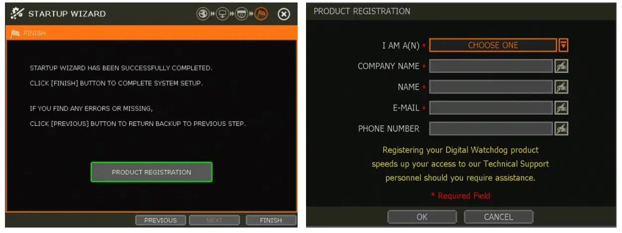
Operation
User Login
Enter the user ID and password. Use the hint button  to check for your password hint if needed.
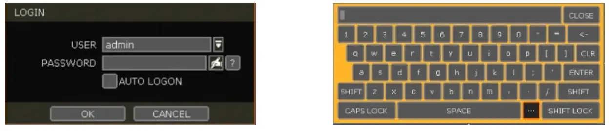
Note
- The login window displays permanently until a user logs in with the right user ID and password.
- The login process is unnecessary if the module is set as AUTO LOGON. See “4.1.2 User” for more information.
Note
The key in the virtual keyboard includes common words, such as Admin, root, http://, rtsp://, www., .com, .net, .org etc.
DVR/NVR/CAM Registration
Recorder Connection through the Network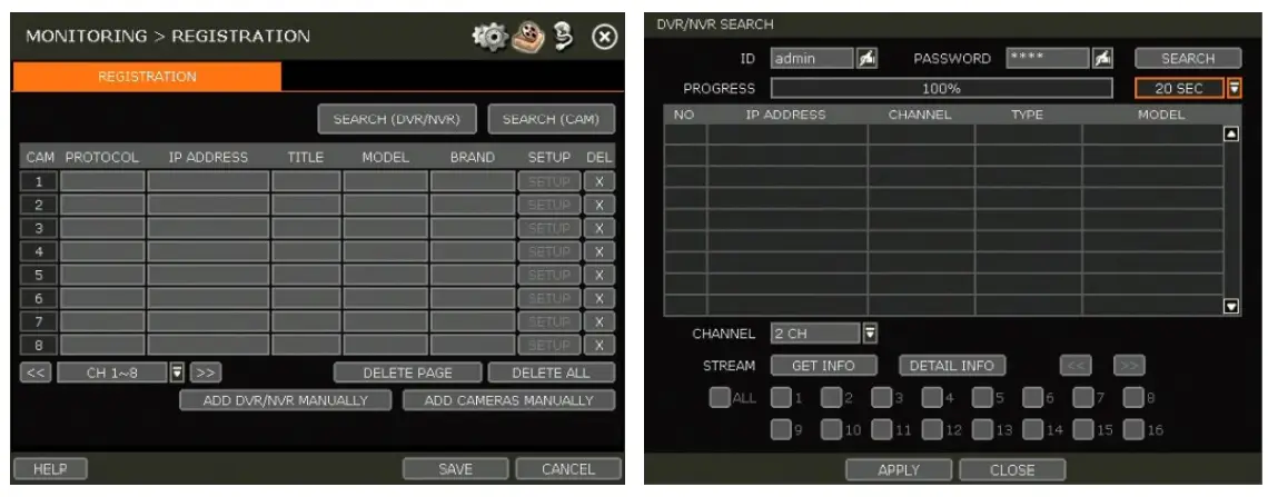
The module will scan the network for all supported DVR/NVR automatically. Select the DVR/NVR to register from the search results and press the ‘GET INFO’ button to obtain the device’s streaming profile. ‘DETAIL INFO’ lets you get more information on the device’s streams. Enter the user ID and password for the device you are registering if necessary. Users can also select which channels from the DVR/NVR to register. Click ‘APPLY’ to register the device.
Camera Connection through the Network
- Click the START button to search the camera. The module will search the network for cameras and display all results in the table on the right.
- Select the camera in the list and drag and drop it to the channel to assign to the camera. (While moving, the mouse pointer is changed to
 ).
). - Click the CLOSE button to save the registration.
Add DVR/NVR Manually
If a user wants to connect to DVR/NVR in a different network, DVR/NVR can be added manually using the ADD DVR/NVR MANUALLY button.
- Click the SEARCH button to open the camera property window.
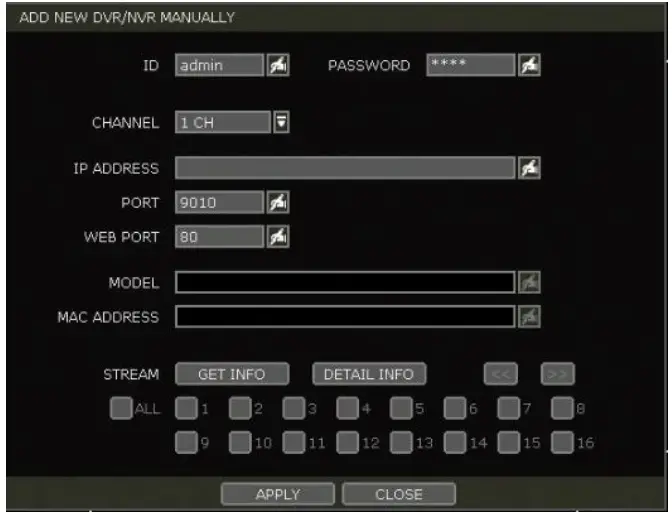
- Select the channel number to register.
- Input necessary information using the
 button and click the GET INFO button to get stream information.
 - Select the channel to register.
- Click the APPLY button to register DVR/NVR.
Manually add Cameras
If a user wants to connect to an IP camera in a different network, the cameras can be added manually using the ADD CAMERAS MANUALLY button.
- Click the ADD CAMERAS MANUALLY button to open the camera property window.
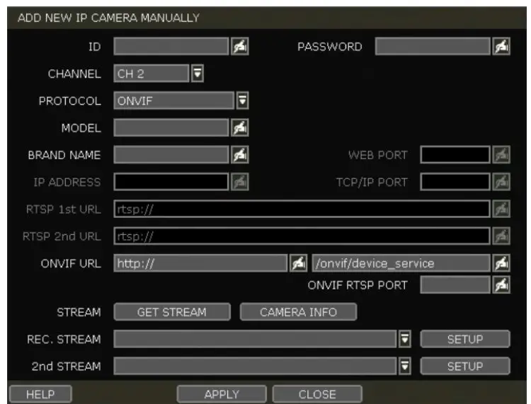
- Select the channel number to register.
- Select the camera’s protocol (ONVIF, RTSP, FOCUS, and VHT). Registration is available for one of the following: – IP Address, RTSP URL or ONVIF URL
- Input the necessary information using the button and click the GET STREAM button to get stream information.
- Click the APPLY button to register the camera.
Adding a recorder or camera using RTSP
- Click on the ADD CAMERAS MANUALLY button.
- Enter the DVR’s user ID and password.
- Select which channel to add to the Spot Monitoring Module.
- Under Protocol, select RTSP instead of ONVIF (default).
- Enter the DVR’s model and brand names (optional).
- Enter the DVR’s RTSP URL in the first RTSP field.
a. To add DW’s VMAX® A1™ DVR, the RTSP URL should be as follows: rtsp://xxx.xxx.xxx.xxx:port/rtsp/unicast/live/profile-x For example: rtsp://192.168.1.100:80/rtsp/unicast/live/profile-1 - Enter the device’s IP address: xxx.xxx.xxx.xxx.
- Port: Use the device’s web port (default value is 80).
- Profile-x: Enter the channel number to add.
- Press the APPLY button to save changes
Deleting Devices
- Click the delete (
 ) button to delete each DVR/NVR or camera.
 - Click the DELETE PAGE to delete devices on the same page, and click the DELETE ALL to delete all devices.
Live Display Mode
Channel Selection
The live image can be seen by easy button operation after power-up. The images can be seen in 1, 4, 9 and 16 screen splits (some split options may not be available according to the module’s number of channels). Whenever the screen display mode button ( ) on the toolbar is clicked, the screen will change to display the next channel or sequence of channels.Click on the selected channel to switch from a multi-channel view to a single camera. To return to the previous screen mode, click the left mouse button again. “VIDEO LOSS” is shown on the display screen when no camera is connected or when it disconnects suddenly. Depending on the system setting, a warning sound is generated when a camera is disconnected. Admin users can set different authorization levels for each user, granting them specific access to specific channels. If a certain user is not authorized to view a channel, no image is shown on the display screen, as shown below.
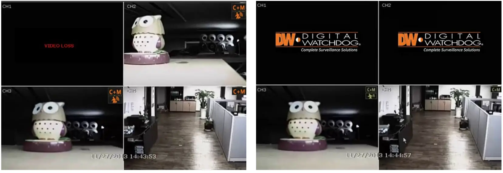
Icons
The Spot Monitoring Module shows the channel’s current status based on the settings in the DVR or NVR.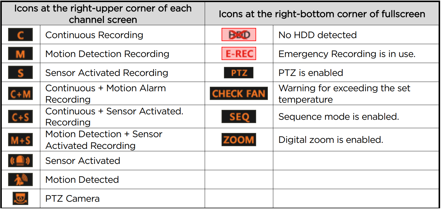
Note
If users cannot find any recording icon in the right corner of the screen, then the system is not recording. Check the recording schedule or camera in the main setup menu.
Pop-up Menu
Users can click the mouse’s right button to pop up the sub-menu, as shown below. If the user wants to control a specific channel, put the mouse cursor on that channel and then click the right button.
Display Mode
Users can change the screen display mode from the available split options.
Change Next CH
- View the next channel or group of cameras in the current split mode.
Sequence
- When “SEQUENCE” is selected, the
 icon will appear on the right-bottom corner of the screen. The display screen will be sequentially changed.
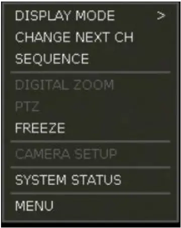
Digital Zoom
- Digital Zoom is available for single-channel viewing only. When “ZOOM” is selected, the
 icon will appear on the bottom-right corner of the screen, and digital zoom control is available.
 - To zoom in, drag the mouse’s cursor on the desired area to create a zoom box. Users can also control zoom-in and zoom-out by scrolling the mouse wheel up and down. Once the image is zoomed in, the user can move the zoom area by clicking on the square’s edge and dragging it.
- To exit from the zoom mode, click the right and select “ZOOM EXIT’ on the menu.
PTZ
Enable PTZ mode. (Please refer to “3.6 PTZ Operation” for details.) The available PTZ options depend on the camera’s ONVIF integration. See the camera’s manual for more information.
Freeze
Freeze the current live view. The system clock (date/time information) will continue running at the bottom of the screen. Select “FREEZE” again to resume the live view.
Camera Setup
View the setup camera menu. Users can set up resolutions, frames, etc. The available options depend on the camera’s ONVIF integration. See the camera’s manual for more information.
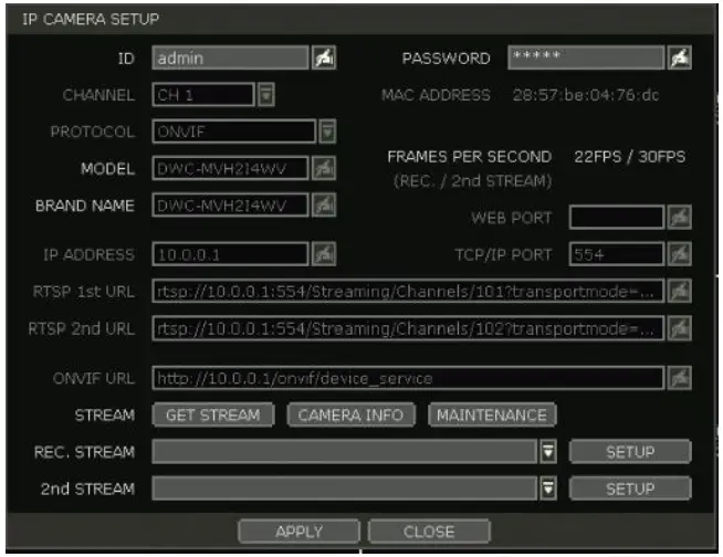
- Click the GET STREAM button and get the current camera status.
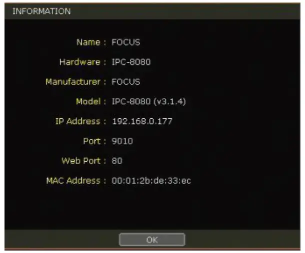
- Click the CAMERA INFO button to check the camera’s information, such as model name, IP address, port, MAC Address, etc.
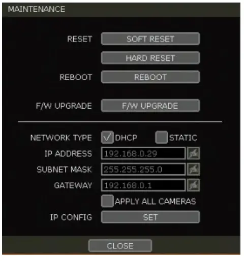
- MAINTENANCE – The user can camera reset, reboot, upgrade firmware, and set up to use the live buffering function on NVR.
Reset
-
- Soft Reset: Reset camera settings except for basic network settings like IP address, subnet, gateway, or DHCP settings.
- Hard Reset: Reset all camera settings (factory reset).
- Reboot- Reboot the camera
- Scheduled Reboot: Set the schedule to reboot the camera
- F/W Upgrade: Upgrade the camera firmware
- Network: Set the camera network setting.
System Status
See the system status, including information on the network condition, the number of clients currently connected to the module, etc. A green line means the connection is live and working.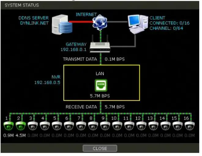
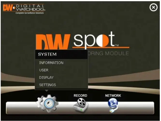
Menu
Open the main menu setup screen.
Setting
The general setting structure consists of “System,” “Monitoring,” and “Network.” Each Setup menu consists of sub-menus and additional categories.
| Main Classification | Sub Classification |
|
SYSTEM |
INFORMATION |
| USER | |
| DISPLAY | |
| SETTINGS | |
| MONITORING | REGISTRATION |
| NETWORK | NETWORK |
| DDNS |
To access the setup menu, click the button in the menu bar or right-click anywhere on the screen and select the Setup Menu.
System
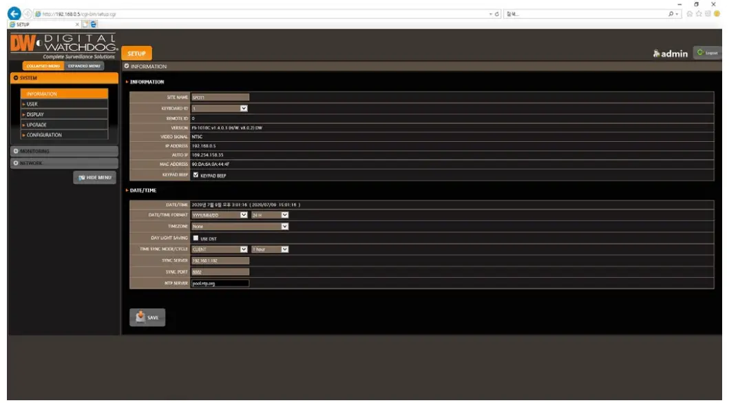
Information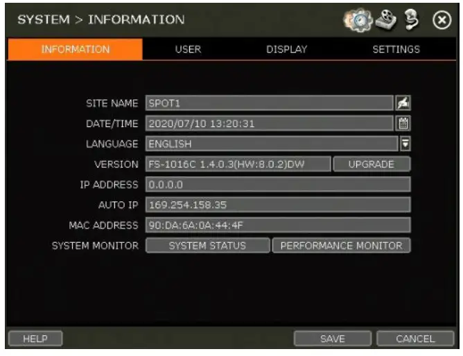
Site Name
Enter a site name to differentiate the module from other sites.
Date/Time
Using the available options, manually adjust the date and time, select the display mode for the time and the date, and select the appropriate time zone. If applicable, check the ‘USE DST’ box.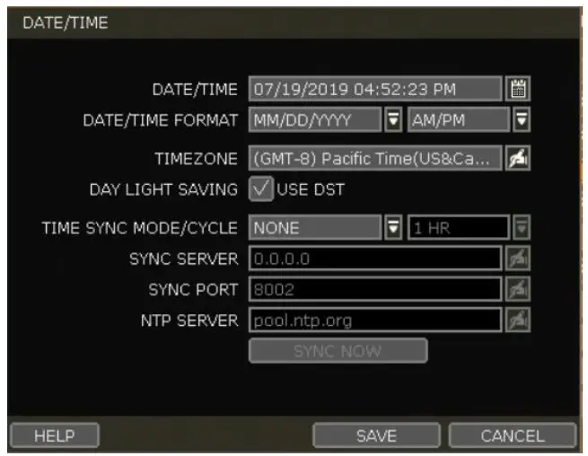
There are four types of time sync modes:
- Server Mode: The operating module is a Time Sync Server, which can synchronize the time to another module (s) connected over the same network.
- Client Mode: Input the IP address of a designated module or PC running Remote Software as a Time Sync Server in “SYNC SERVER.” The module’s time clock will be synchronized with the server by interval time set in “TIME SYNC CYCLE.”
- NTP Mode: “pool.ntp.org” is the recommended NTP Server. To activate, set the TIME ZONE of your local area and then click the SYNC NOW button.
- GPS Mode: Connect a type GPS device and click the SYNC NOW button.
Language
Select the display language from the available options.
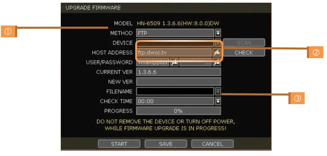
Version
View the module’s current firmware version and update it to a newer version via DVD/CD/USB Memory Stick/FTP server.
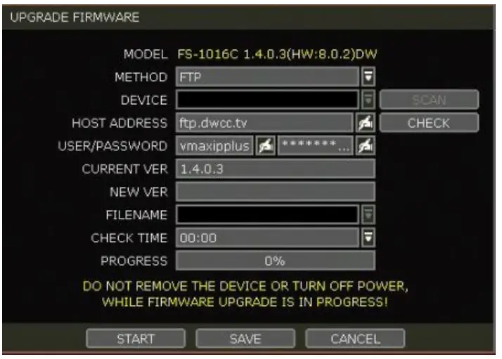
Caution
Do not click CANCEL during the firmware upgrade. It may cause serious damage. Settings may be changed to factory default. Check the settings and operating conditions of the module after the firmware upgrade.
Upgrading system using USB memory stick:
- Insert a USB drive with the firmware file formatted by FAT/FAT32 in any USB port of the module (compatible with USB 2.0). The firmware file must be placed into the USB’s root directory. If the firmware file is placed in a folder, the system may not recognize it.
- Select ‘USB’ from the Method drop-down options and press the SCAN button.
- Once the system detects the USB drive, it will display the firmware file under ‘CURRENT VER’ and the ‘NEW VER.’
- Click START to begin the upgrade process.
Upgrading system using Digital Watchdog’s Automatic Firmware Upgrade via FTP server:
- Select FTP in the drop-down options under ‘Method.’
- Enter the FTP’s address: ftp.dwcc.tv, and enter the username and password (these should be filled out automatically). Username: vmaxipplus, password: vmaxipplus.
NOTE
The FTP server address is subject to change without prior notice. - Enter a value for the Check Time. The system will automatically check the FTP server for newer firmware daily at a set hour.
- Click the OK button to proceed with an automatic firmware upgrade. Once the firmware update is complete, the system will reboot.
- Click the CHECK button to allow the module to connect to the FTP server and check the latest Firmware version. If new firmware is available, the module will ask whether to upgrade it.
- Click the OK button to confirm and click the START button to start upgrading.
To set up the module to check for new firmware automatically:
- Select FT from the METHOD drop-down options.
- Ensure the FTP information is entered correctly (see the section above).
- Enter a convenient time at CHECK TIME and then click the SAVE button.
IP Address
Shows the module’s current IP Address. It can be set at the MENU> NETWORK> NETWORK.
Auto IP
Shows AUTO IP Address of the module.
MAC Address
Shows the unique identity number for the module.
System Monitor
Monitor the system performance and condition.
User
The ADMIN user has full authority over system settings and can change the system password or add/delete users and assign a different permission level to them.
Note
The maximum number of users, including the administrator, is 16.
User Management
Admin users can control authorization for each function. This authorization is applied when the user connects to the module from a remote software.
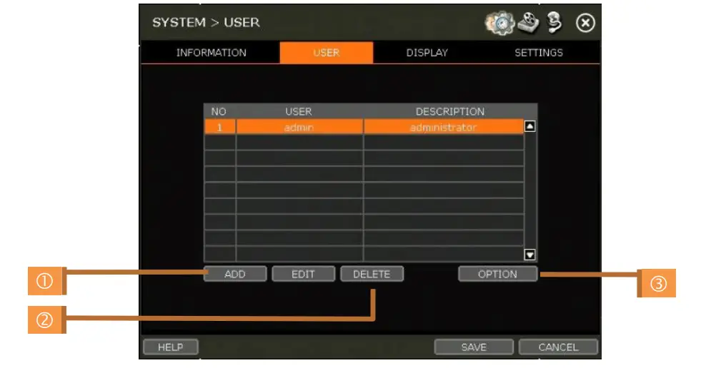
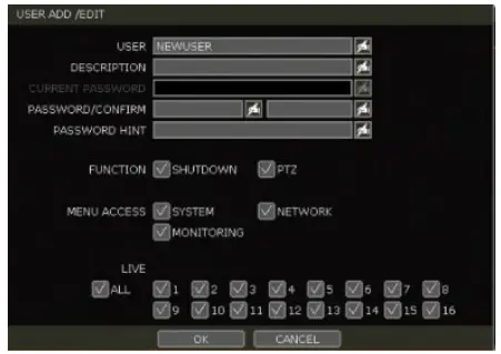
- Add User
- a. Click the ADD button.
- b. In the new setup window, set a new user’s ID, description, password, and password hint.
- c. Select which functions and menu options the user will have access to by checking the box next to the corresponding functions.
- d. Only the selected channels are visible to the user in Live and Playback mode.
- e. To change the setting, select the user and click the Edit button.
- Delete User
- a. Select the user in the list by highlighting their name and clicking the Delete button.
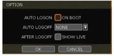
- Option
- a. If Auto Logon “On Boot” is enabled, the module will not request ID and password after power-up.
- b. If “Auto Logoff” is enabled, the module will log off the current user after the set time of inactivity.
- c. If “show live” is checked, the live image will be shown after logging off.
Display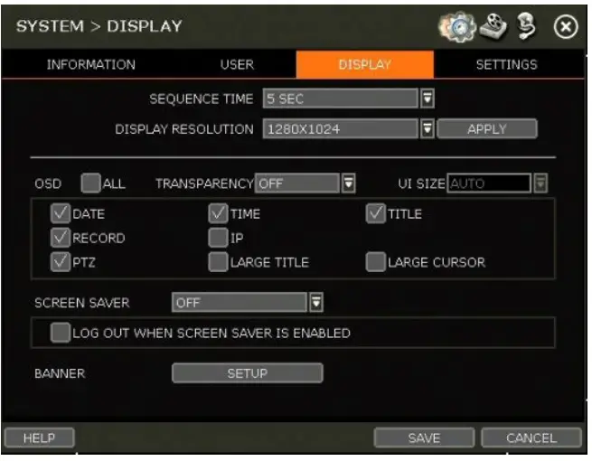
- Sequence
Set the dwell time for the sequence channel display. - Display Resolution
The system supports the following resolutions: 1024×768, 1280×720, 1280×1024, 1920×1080, 2560×1600 (true HD output only) and 3840×2160 (true HD output only). - OSD
Select what information will appear over the display by checking the corresponding boxes. - Screen Saver
Protect the screen and data by turning off the display after a set time of inactivity. Set the screen saver’s time for the monitor to turn off automatically. Set in between 1 minute and 180 minutes. If applicable, select to log off the current user when the screen saver is on. - Banner
Create the banner and display it on the screen. Users can set font size, position, interval and font color.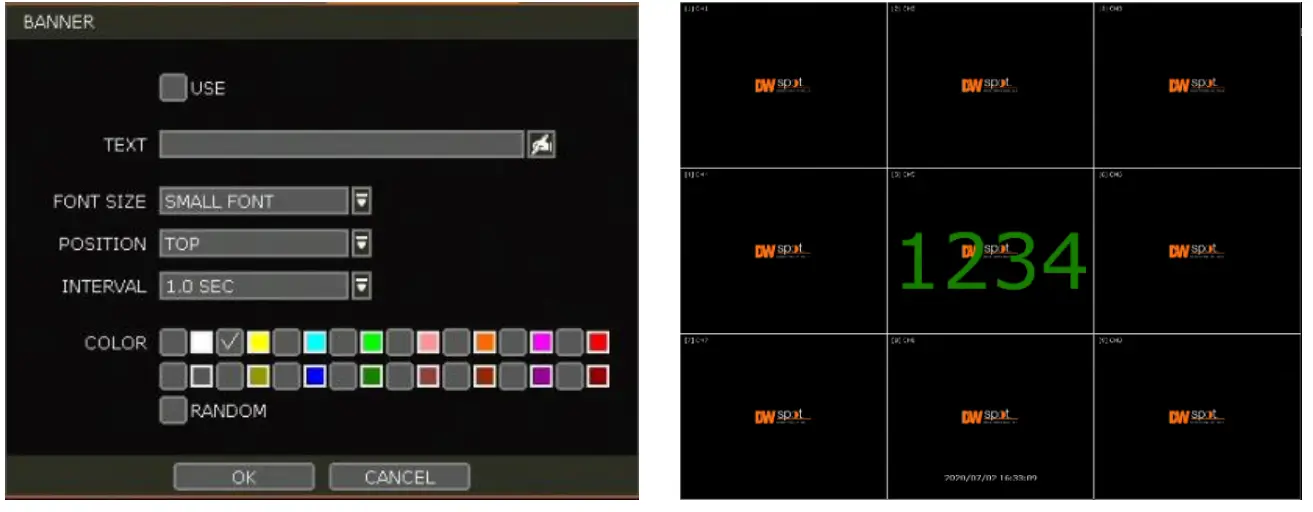
Settings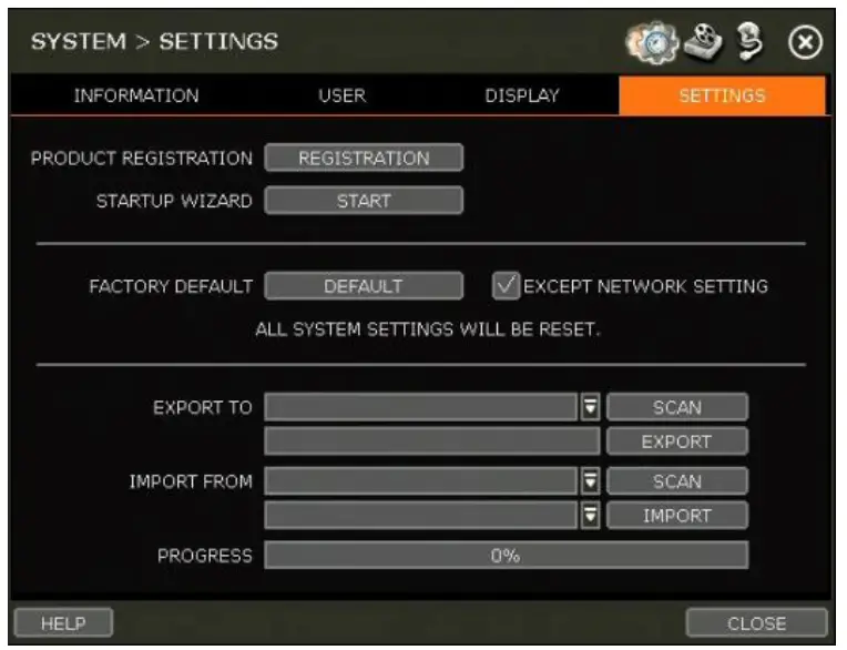
Product Registration
Register your product with DW to enhance your technical support experience, if needed, and stay informed of the latest updates and product information.
Startup Wizard
Manually start the startup wizard.
Factory Default
Reset the system to its factory default settings. All settings will be deleted, including the network settings. To keep the system’s network settings from resetting, check the box next to the Factory Default button to exclude the current network settings from being reset.
Export/Import
Copy the system settings between modules. Users can export the current module’s settings and apply them to other modules or apply settings from a previous module to the current one.
- Export: copy the settings of this system to a USB memory device.
- Import: apply settings from another module via CD/DVD/USB memory device.
During the import process, make sure that the F/W version of the sourced module is the same as the target module.
Monitoring
Registration
Users can register/delete devices by letting the module scan and register devices automatically or manually search and add devices.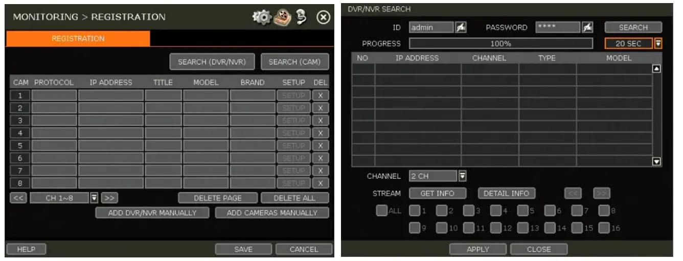
The module will scan the network for all supported DVR/NVR automatically. Select the DVR/NVR to register from the search results and press the ‘GET INFO’ button to obtain the device’s streaming profile. ‘DETAIL INFO’ lets you get more information on the device’s streams. Enter the user ID and password for the device you are registering if necessary. Users can also select which channels from the DVR/NVR to register. Click ‘APPLY’ to register the device.
Camera registration
Users can register the camera by drag & dropping way. (Please refer to “3.2.2. Camera connection through the network”).
Select the camera in the list and drag and drop it to the channel to assign to the camera. (While moving, the mouse pointer is changed to.) Click the CLOSE button to complete the camera registration.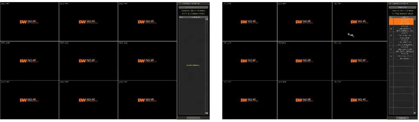
Deleting Devices
Click the delete (/ ) button to delete each DVR/NVR or camera. Click the DELETE PAGE button to delete devices on the same page, and click the DELETE ALL button to delete all devices.
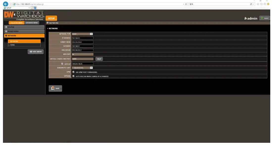
Network
The module can be connected to the network or internet through fixed IP or dynamic IP by properly setting the module and router.
Network
- Network Type
DHCP: The module will automatically acquire all the network settings according to the current network requirements. Click the ‘IP DETECT’ button to fill out all the network settings automatically. Static IP: manually enter all the network settings. For proper configuration, it is recommended that the module be assigned a DHCP address and let it auto-discover all the appropriate network settings. Then, change the Network Type to Static IP and save the changes. Contact your Network Administrator for more information. - IP Address
If DHCP is selected, the IP address will automatically adjust to match the network’s requirements. Users can also manually change the IP address as needed. - Subnet Mask
The Subnet Mask address classifies the subnet to which the system belongs. Contact your Network Administrator for more information. - Gateway
This is the IP address of the router or gateway server. It is required when connecting to the module through the external router over the internet (from another network). Contact your Network Administrator for more information. - DNS Server
Enter the IP address of the Domain Name Server. Users should input the DNS Server information to use DDNS, E-mail notifications and NTP Server. Contact your Network Administrator for more information. - WEB Port
Input the port number to use when connecting from the Web Browser. The default is 80. Contact your Network Administrator for more information. - Auto IP
Displays the system’s IP address. - Use UPnP (Universal Plug and Play)
UPnP is a plug-and-play feature that allows the module to be automatically discovered by a PC on the same network. Go to “My Network” on your PC to locate the module. The computer will scan your network for all supported devices. The first five characters of the file name of a detected module represent the model number, followed by the module’s IP address.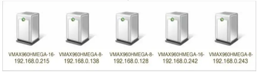
Once the PC discovers the module, double-click the icon to open the module’s web client. Enter your User ID and Password to log in and click ‘Connect.’
Note
The maximum number of simultaneous connections is 15 users.
Maintenance
Check the network status and set up the Mac address filter, IP address filter and HTTPS certificate.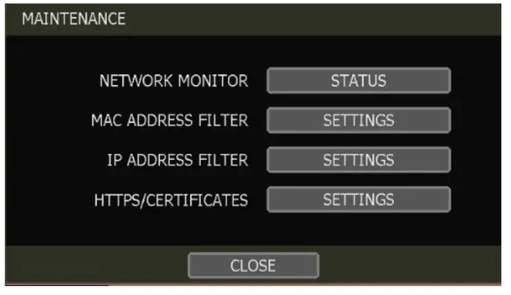
Network Monitor
Check the network status of each camera and data flow information for the module and cameras.
MAC Address Filter
This function allows or blocks a specific Mac address from a client such as 3C™ CMS or mobile. When the user registers a specific Mac address to allow, only that address can access the module by the client. Or when a user registers a specific Mac address to block, that address can’t access the module by the client. This function works only on the local network and does not work on web Login.
IP Address Filter
This function allows or blocks a specific IP address. When a user registers a particular IP address to allow, only that address can access the module. Or when a user registers a particular IP address to block, that address can’t access the module. This function is not working on web Login.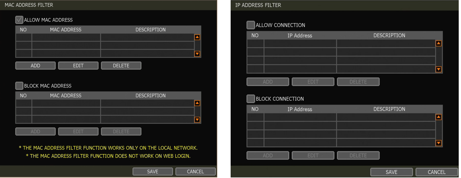
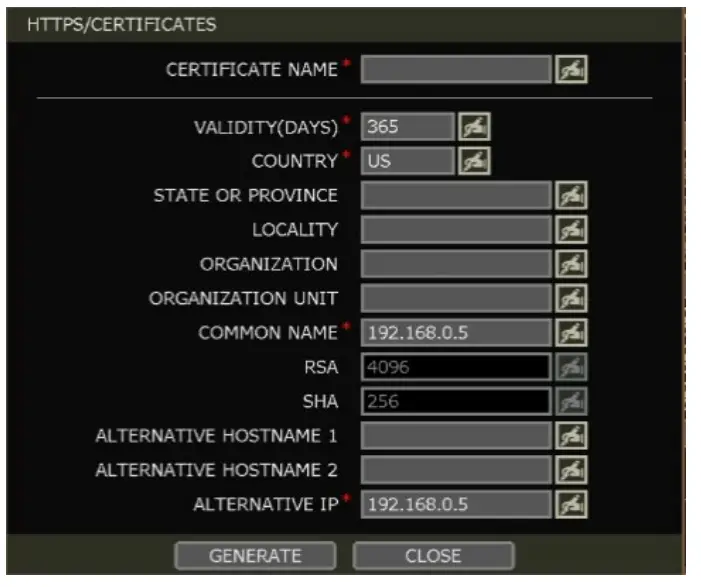
HTTPS/Certificates
Register self-signed certification for the HTTPS connection. Register a new certificate by clicking ‘Generate’ or register an external certificate by clicking ‘Import.’
To register a new certificate:
- Enter the certificate’s basic information. Enter all fields marked with (*).
- Before generating the certificate, the module and network time zones must match. Otherwise, the generated certificate’s validity period may differ, and the certificate application’s timing may vary.
- Once the certificate generation is complete, the validity will be displayed.
DDNS
Users can use either a public DDNS server or the DDNS server operated by the module maker (dynlink.net) to connect through dynamic IP.
DDNS Server
Digital Watchdog® offers free and reliable DDNS service support. This allows users to assign the module a URL address rather than a long, complicated IP Address. This simplified the connection process to the module. Digital Watchdog® supports the DDNS service and is free of charge for our customers. To setup DDNS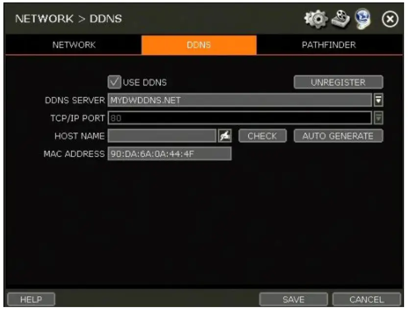
Input necessary information based on your network environment. And then click the SAVE button.
- Enable Use DDNS box
- DDNS SERVER: Select DYNLINK.NET or MYDWDDNS.NET
- TCP/IP PORT: Default is 80.
- HOSTNAME: Assign a domain name for your module (ex, module office). If the same domain name is assigned, the message still pops up when clicking the CHECK button. The hostname can be automatically assigned by clicking the AUTO GENERATE button.
IP Mapping and External IP
If using IP Mapping and Port Forwarding (e.g., using the router for internet connection), enable both [Use Device IP Mapping] and [Use External IP] for proper connection.
Setting up the Remote Software (CMS)
- In the menu Option > Setting, input the DDNS Address and Port number.
- The address of the DDNS SERVER is “dynlink.net” and the Port is “80”.
Setting at the Web Browser
- Users can type the module’s MAC address + dynlink.net.
- In case users are using a subdomain name, type the domain name + dynlink.net
- Ex) 1. If Mac address is “00:1C:84:01:00:02” -> input as “http://001c84010002.dynlink.net”
- 2. If the domain name is “DVROFFICE” -> input as “http://DVROFFICE.dynlink.net“
Web Surveillance through Internet Explorer
The Spot Monitoring Module has a built-in web server by itself. This allows users to access the system by a web browser via a network for live monitoring, playback, or remote configuration without installing additional software.
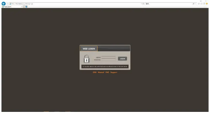
Web Login
In an Internet Explorer page (Windows OS only), type the module’s IP Address or DDNS address in the address bar. When the login page appears, enter the user ID and password. Once connected to the module, users will be prompted to download and install the Active X file.
Active-X Installation
- The installation guide message will appear automatically if the PC doesn’t have Active-X installed.
- Click ‘install’ and follow the installation wizard to complete the ActiveX installation.

- Ensure Active X controls are enabled in the web browser’s security settings to avoid download restrictions for the Active X file. Go to “Tools > Internet Options > Security > Internet > Custom Level” and allow all Active X controls and plug-ins.
- Failing to install the Active X files properly may result in the module not showing a video.
Web Setup
Setup Menu
| Main Classification | Sub Classification |
|
SYSTEM |
INFORMATION |
| USER | |
| DISPLAY | |
| UPGRADE | |
| CONFIGURATION | |
| MONITORING | CAMERA MANAGEMENT |
| REGISTRATION | |
| NETWORK | NETWORK |
| DDNS |
System Setup
Users can set up the module’s system settings through the web browser.

Monitoring
Users can check the information, take a snapshot of the currently connected device, and register a new device.
Network
Users can set up network settings and DDNS settings
- Note
This module system has a built-in web server. Therefore, this web CGI screen is directly supported by the built-in web server of modules regardless of Internet connection. - Note <System Reboot> enables users to reboot the system without changing the setup. Users can use this function when the network is disconnected due to abnormal system operation and try to reconnect. The IP number assigned to the system may be changed in DHCP mode
Product Specifications
| DW-HDSPOTMOD | DW-HDSPOTMOD16 | ||
| OPERATIONAL | |||
| Operating system | Embedded Linux® | ||
|
Video in |
Input | 4 channels | 16 channels |
| Protocol | ONVIF | ||
| Input resolution | IP cameras (up to 4K, 3840 x 2160 resolution), Universal HD over Coax® VMAX® A1™ DVRs or VMAX® IP Plus™ NVRs | ||
|
Video output display |
Speed | Up to 120fps | Up to 480fps |
| Maximum throughput | 80 Mbps | ||
| Monitor | True HD or VGA | ||
| Resolution | True HD: 3840×2160, 1920×1080, 1280×720, 1024×768 / VGA: 1920×1080, 1280×720, 1024×768 | ||
| Screen mode | 1, 4, sequence | 1, 4, 9, 16, sequence | |
| LAN | 10/100/1000Mbps gigabit ethernet (RJ45) | ||
| Protocols | TCP/IP (STATIC, DHCP), DDNS and UPNP | ||
| Streaming | Dual-streaming | ||
| Network function | Time synchronization by the NTP server | ||
| Remote management via web (IE) | System settings | ||
| System recovery after power failure | Auto-reboot and log file system | ||
|
Advanced functions |
Firmware upgrade by USB and CMS | ||
| Import and export settings | |||
| Digital zoom | |||
| System operation | USB mouse | ||
| ENVIRONMENTAL | |||
|
Surge Protect |
ESD | Air ±15KV / Contact ±10KV | |
| Surge | Video IN ±4KV (Line to Line 1.2us/50us) | ||
| Power | DC12V, 1A | ||
| Operating temperature | 41°F ~ 104°F (5°C ~ 40°C) | ||
| Operating humidity | 20–90% RH (non condensing) | ||
| Dimensions | 5.47″ x 4.84″ x 1.25″ Inch (139 x 123 x 32 mm) | ||
| Warranty | 5 year warranty | ||
Specifications are subject to change without notice.
Warranty Information
Go to https://digital-watchdog.com/page/rma-landing-page/ to learn more about Digital Watchdog’s warranty and RMA. To obtain warranty or out-of-warranty service, please contact a technical support representative at: 1+ 866-446-3595, from 9:00 AM to 8:00 PM EST, Monday through Friday.A purchase receipt or other proof of the original purchase date is required before warranty service is rendered. This warranty only covers failures due to defects in materials and workmanship that arise during normal use. This warranty does not cover damages that occur in shipment or failures that are caused by products not supplied by the Warrantor or failures that result from accident, misuse, abuse, neglect, mishandling, misapplication, alteration, modification, faulty installation, setup adjustments, improper antenna, inadequate signal pickup, maladjustments of consumer controls, improper operation, power line surge, improper voltage supply, lightning damage, rental use of the product or service by anyone other than an authorized repair facility or damage that is attributable to acts of God.
Limits and Exclusions
There are no express warranties except as listed above. The Warrantor will not be liable for incidental or consequential damages (including, without limitation, damage to recording media) resulting from the use of these products or arising out of any breach of the warranty. All express and implied warranties, including the warranties of merchantability and fitness for a particular purpose are limited to the applicable warranty period set forth above. Some states do not allow the exclusion or limitation of incidental or consequential damages or limitations on how long an implied warranty lasts, so the above exclusions or limitations may not apply to you. This warranty gives you specific legal rights, and you may also have other rights that vary from state to state.
If the problem is not handled to your satisfaction, then write to the following address:
- Digital Watchdog, Inc.
- ATTN: RMA Department
- 16220 Bloomfield Ave
- Cerritos, CA 90703
Service calls that do not involve defective materials or workmanship, as determined by the Warrantor in its sole discretion, are not covered. The cost of such service calls is the responsibility of the purchaser.
FAQ
- Q: What should I do if the power button does not work?
- A: If the power button does not respond, press and hold it for 5 seconds to turn off the power.
- Q: Can I expose the product to rain or humidity?
- A: No, do not expose the product to fog, rain, or excessive humidity to prevent electric shock or firehazards.
Documents / Resources
 |
Digital Watchdog DW SpotTM Monitoring Module [pdf] User Manual DW SpotTM Monitoring Module, DW SpotTM, Monitoring Module, Module |