DIGI Modbus DC DAL Routers Installation Guide
![]()
Modbus DC Installation Instructions for Digi DAL Routers
Change Log

Installation and Auto-Start Instructions
The following instructions are to be executed within the web interface of the Digi DAL Routers
a) Installation
Upload mb_dc.zip, and the desired config.cfg, slaves.cfg and any necessary register map CSV files onto the root directory of Digi DAL Routers using FTP Uploading a newer version will require uploading a new mb_dc.zip.
b) Setting the Application to auto-start via the web interface
- a. Login into the Local Web UI
- b. Navigate to System -> Scheduled tasks -> Custom Scripts
- c. To add optional arguments click the + Add Script button.
- d. Enter `python mb_dc.zip [optional arguments]’ to the custom scripts list (without quotes)
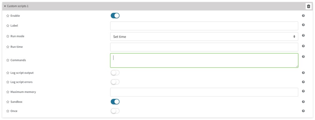
- e. Enable the custom script.
- f. Add a label that will be used to identify the custom script.
- g. Choose the mode that will be used.
- h. Choose a runtime which will be a specific time that task will run in this format HH:MM
- i. You can choose to enable or disable logging the script output using stdout stream to system log.
- j. You can choose to enable or disable logging the scripts stdeer stream to system log.
- k. Choose the maximum amount of memory for the custom script and its spawned processes that you may want to allocate.
- l. You can choose to Enable or Disable to run the script in the Sandbox to prevent the behavior from affecting the system.
- m. Choose to enable or disable to run the script once at a specified time refer to (h)
- n. Click “Apply” on the top right to apply the changes.
c) Add Parameters
optional arguments:
-h, –help show this help message and exit
–debug, -d Show extra output
–file_log, -l Turn on information and debug messages to file logging
–print_log, -p Print information and debug messages to terminal
Slaves.cfg Configuration File
The Slaves.cfg file contains the information of the end Modbus slaves that will be communicated with the application. The following information outlines the parameters of the Slaves.cfg configuration file:
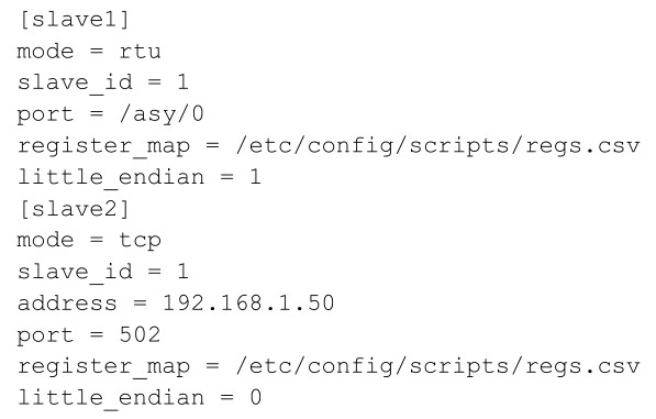
a) [slave1]/[slave2] – Configuration section name of specific, individual slave. This will be used for the datastream name and is required when writing registers.
b) mode - Mode of communication. Options are “tcp” or “rtu”.
c) slave_id - Slave ID of slave. This will be used when creating a read or write query to the device.
d) address - IP address of slave. This is required of “tcp” mode only.
e) port - If “rtu” mode, this is the port name of the TransPort’s serial adapter that is attached to the slave. If “tcp” mode, this is the TCP port of the slave (if unknown, use 502).
f) register_map - File path of register map file
g) little_endian - 0 = higher bits are in the lower register ; 1 = lower bits are in the lower register.
If little_endian is not defined in the slaves.cfg file, the application will use the default big endian (little_endian = 0).
Config.cfg configuration file
The Config.cfg file contains the information of how often the application will poll for data and upload that data to Digi Remote Manager. This section outlines the parameters of the Config.cfg file:
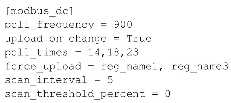
a) [modbus_dc] Configuration section name of general application options.
b) poll_frequency Time, in seconds, to wait between register reads. The Modbus register values
are uploaded when starting the mb_dc application. Uploads will take place every poll frequency seconds if the register read value has changed. Polls are scheduled starting at midnight. For example, if this is set to 300, then polls would occur as 12:05am, 12:10am, 12:15am, etc. Default is 900. If poll_frequency = 0, the poll_times, described below, will be applied.
c) upload_on_change True/False. When true, the application will continuously scan the defined slaves/registers and upload the items that change. Default is False.
d) poll_times Integer list of times for the sensor to conduct a measurement. The times given in this setting corresponds to UTC. The poll_times settings is only applied if the poll_frequency setting is equal to 0. Otherwise the poll_times setting is ignored. The poll_times is an optional config.cfg entry. If poll_times is not in config.cfg, the poll times will be every hour 1 23.
e) force_upload A comma separated list of registers that should always be uploaded during a poll, regardless of whether they have changed or not. Default is empty (disabled).
f) scan_interval Number of seconds to wait between scans for changes. This is only used when upload_on_change is set to true. Default is 5.
g) Scan_threshold_percent Minimum percentage change that a value must meet to be considered new when using upload_on_change feature. Setting this to 0 disables this feature. Default is 0 (disabled).
Register Map CSV Columns
The CSV file must include the following headers, in order from left to right. Required headers: the register_type, name, data_type and starting_address columns are required. The length is required if the data_type is “Char”. See the following descriptions for additional requirements when using the reset_delay and/or data_factor features. An example CSV file is included with the application.
a) register_type Type of register that holds described data. Options are `coil’, `discrete_input’, `holding_register’, and `input_register’. The register_type value is required.
b) name Name of datastream that will receive register data. This name will also be used when writing values. The name value is required.
c) data_type Type of data contained in register. Options (# registers):
a. Int (2)
b. Float (2)
c. Char (user defined)
d. long_long (4)
e. unsigned_long (2)
f. unsigned_short (1)
g. unsigned_long_long (4)
h. short (1)
i. double (4)
j. long (2)
k. unsigned_int (2)
d) starting_address Address of Modbus register that contains data item. The starting address is required.
e) length Count of registers to poll to get entire data item. This field is required if data_type = char, otherwise the application will override this field with the # registers defined in the data_type description above. A value (empty value is acceptable) is required for this column if the reset delay or data_factor is required. See the following descriptions of reset_delay and data_factor.
f) reset_delay After writing a register, reset_delay is the minimum number of seconds that will elapse before the register is set to `0′. Registers with a reset_delay will be set to `0′ when the application starts. This column is required (default = 0 = no reset) If a data_factor is required.
g) data_factor Register write: value will be divided by the data_factor before the register write is performed. Register read: value will be multiplied by the data_factor before uploading the value to Remote Manager Data Stream. This column is not required. The default value is “1”.
Reading Modbus Registers
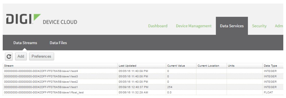
a. The values of Modbus registers defined in the configuration files will be uploaded to Device Cloud DataStreams. The stream name will be based on the device ID of Digi DAL Device, the slave name, and the data name. Routine polling will occur based on the poll_frequency configuration setting.
b. A poll can be initiated via the “scan_now” callback. Example:
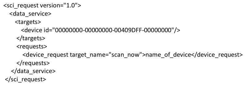
The device_id should be your desired device and “name_of_device” should be replaced with the name of the device configured in slaves.csv.
Writing Modbus Registers
c. Modbus registers or coils that are defined in the configuration files can be written to using a Device Cloud SCI request. Example:

The text of the “device_request” element will be send to the application. Three arguments, separated by commas, are required.
- First argument: Name of slave, defined in slaves.cfg
- Second argument: Name of data, defined in register map assigned to name of slave
- Third argument: Value to write. Must be an integer
For more information about sending an SCI request, see the following page:
https://www.digi.com/wiki/developer/index.php/SCI#Sending_the_request_and_getting_the_response
The response will indicate success or failure of the write in the “status” attribute of the “response” element. Example:
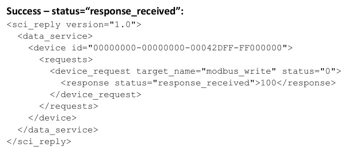
This response indicates that a response was received from the Modbus slave. The value received from the Modbus slave is contained in the text of the “response” element. Confirm that this value is what you expect after writing the register/coil. The expected “response” from the slave device include response = “register value” when writing a Holding Register of length 1 (short for example) and response = “2” (word count or number of registers) when writing a Holding Register of length 2 (integer and float for example)

If the “status” attribute of the “response” element is “failed”, one of the following error messages will be shown in the text of the “response” element.
- Incorrect arguments - The arguments supplied in the SCI request were not in the following format:
- Name_of_slave,name_of_data,5
- Write failed - The Modbus slave write failed to successfully process.
- Slave not found - The slaves.cfg file does not contain information about the requested slave name.
- Failed to attempt write before timeout, resource busy - The application was performing other IO operations before the task was processed within the 30 second timeout.
Documents / Resources
 |
DIGI Modbus DC DAL Routers [pdf] Installation Guide Modbus DC DAL Routers, DC DAL Routers, DAL Routers, Routers |