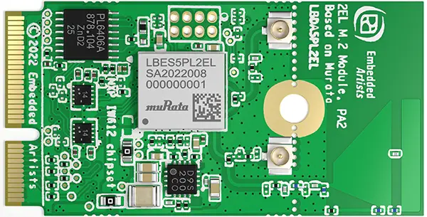
DIGI LBES5PL2EL Communication Module
Product Information
- Model Name: LBES5PL2EL, LBEE5PL2DL
- FCC ID: MCQ-CC93
- Compliance: Part 15 of the FCC Rules
Product Usage Instructions
- Installation:
This module should be installed in the host device according to the interface specification provided in the installation procedure. - Regulatory Compliance:
The OEM integrator should not provide information on how to install or remove this RF module to end users. The end user manual should include all required regulatory information and warnings.
FCC Compliance:
- This device complies with Part 15 of the FCC Rules, ensuring that it does not cause harmful interference and accepts any interference received.
- FCC Caution: Any changes or modifications not approved by the responsible party could void the user’s authority to operate the equipment.
- The transmitter must not be co-located or operated with any other antenna or transmitter.
Integration Instructions:
For integrating the module in a host product, refer to the integration instructions provided. Make sure to include all necessary information in the OEM instruction manual for a seamless integration process.
FAQ
Q: What if the FCC ID is not visible when the module is installed inside another device?
A: If the FCC ID is not visible, the module must display a label referring to the enclosed module.
FCC STATEMENT
- Since this module is not sold to general end users directly, there is no user manual of the module.
- For the details about this module, please refer to the specification sheet of the module.
- This module should be installed in the host device according to the interface specification (installation procedure)
- The OEM integrator has to be aware not to provide information to the end user regarding how to install or remove this RF module in the end user’s manual of the end product which integrates this module.
- The end user manual shall include all required regulatory information/warnings as shown inthe User manual.
- This device complies with part 15 of the FCC Rules. Operation is subject to the following two conditions: (1) This device may not cause harmful interference, and (2) this device must accept any interference received, including interference that may cause undesired operation.
- FCC CAUTION Changes or modifications not expressly approved by the party responsible for compliance could void the user’s authority to operate the equipment.
- This transmitter must not be co-located or operated in conjunction with any other antenna or transmitter.
- This device complies with part 15 of the FCC Rules.
- Part 15 Subpart C
- Part 15 Subpart E
Since no space indicates FCC ID on this module, FCC ID is indicated in a manual. If the FCC ID is not visible when the module is installed inside another device, then the module is installed must also display a label referring to the enclosed module.
- The modular transmitter is only FCC-authorized for the specific rule parts (i.e., FCC transmitter rules) listed on the grant, and the host product manufacturer is responsible for compliance to any other FCC rules that apply to the host not covered by the modular transmitter grant of certification.
- The final host product still requires Part 15 Subpart B compliance testing with the modular transmitter installed.
- This module is designed for mounting inside of the end product by us professionally.
- Therefore, it complies with the antenna and transmission system requirements of §15.203.
- Since no space indicates FCC ID on this module, FCC ID is indicated in a manual.
- If the FCC ID is not visible when the module is installed inside another device, then the module is installed and must also display a label referring to the enclosed module.
- The modular transmitter is only FCC-authorized for the specific rule parts (i.e., FCC transmitter rules) listed on the grant, and the host product manufacturer is responsible for compliance to any other FCC rules that apply to the host not covered by the modular transmitter grant of certification.
- The final host product still requires Part 15 Subpart B compliance testing with the modular transmitter installed.
This manual is based on KDB 996369, which is designed to ensure that module manufacturers correctly communicate the necessary information to host manufacturers that incorporate their modules.
INTEGRATION INSTRUCTIONS
- General: Applicable
Sections 2 through 10 describe the items that must be provided in the integration instructions for host product manufacturers (e.g., OEM instruction manual) to use when integrating a module in a host product. This Modular transmitter applicant (DIGI) should include information in their instructions for all these items indicating clearly when they are not applicable. - List of applicable FCC rules: Applicable
This device complies with part 15 of FCC Rules.- Part 15 Subpart C
- Part 15 Subpart E
- Summarize the specific operational use conditions: Applicable
- This module is designed for mounting inside of the end product by us professionally.
- Therefore, it complies with the antenna and transmission system requirements of §15.203.
- Limited module procedures: Applicable
This module needs to supply a regulated voltage from the host device.
- Since no space indicates FCC ID on this module, FCC ID is indicated in a manual. If the FCC ID is not visible when the module is installed inside another device, then the module is installed and must also display a label referring to the enclosed module.
- Trace antenna designs: Applicable
Please perform the Trace antenna design that follows the specifications of the antenna. The concrete contents of a check are the following three points.- It is the same type as the antenna type of antenna specifications.
Confirm the same size as the Gerber file. - An antenna gain is lower than a gain given in antenna specifications.
Measure the gain, and confirm the peak gain is less than the application value. - The emission level is not getting worse.
Measure the spurious, and confirm degradation of less than 3dB than the spurious value of worst of report used for the application. However, it is spurious defined below. Please send those reports to DIGI.
Please refer to the Antenna in Section 6 of the installation manual.
- It is the same type as the antenna type of antenna specifications.
- RF exposure considerations: Applicable
This equipment complies with FCC radiation exposure limits set forth for an uncontrolled environment and meets the FCC radio frequency (RF) Exposure Guidelines. This equipment should be installed and operated keeping the radiator at least 20cm or more away from the person’s body.- It is necessary to take a SAR test with your set mounting this module (except to use only Bluetooth).
- Class II permissive change application is necessary using the SAR report. Please contact DIGI.
- An application for a Class II permissive change from Mobile equipment to Portable equipment is also required.
Note - Portable equipment: Equipment for which the spaces between the human body and the antenna are used within 20cm.
- Mobile equipment: Equipment used at the position in which the spaces between the human body and antenna exceed 20cm.
- Antennas: Applicable
Part number
Vendor
Peak Gain(dBi) Type
Connector
2.4GHz 5GHz 146153 Molex 3.2 4.25 Dipole u.FL 219611 Molex 2.67 3.67 Dipole u.FL WT32D1-KX Unictron 3.0 4.0 Dipole u.FL W24P-U Invertek 3.2 N/A Dipole u.FL Type2EL_Antenna Murata 3.6 4.6 Monopole Trace - No.4 W24P-U can only be used at 2.4GHz
- No.5 Type2EL_Antenna can only be used for ANT0(Antenna Port0)
- Label and compliance information: Applicable
The following statements must be described in the user manual of the host device of this module;- Contains Transmitter Module FCC ID: MCQ-CC93
or - Contains FCC ID: MCQ-CC93
- This device complies with part 15 of the FCC Rules. Operation is subject to the following two conditions: (1) This device may not cause harmful interference, and (2) this device must accept any interference received, including interference that may cause undesired operation.
- If it is difficult to describe this statement on the host product due to the size, please describe it in the User’s manual.
FCC CAUTION
Changes or modifications not expressly approved by the party responsible for compliance could void the user’s authority to operate the equipment. - Compliance with FCC requirement 15.407(c)
Data transmission is always initiated by software, which is passed down through the MAC, through the digital and analog baseband, and finally to the RF chip. Several special packets are initiated by the MAC. These are the only ways the digital baseband portion will turn on the RF transmitter, which it then turns off at the end of the packet. Therefore, the transmitter will be on only while one of the aforementioned packets is being transmitted. In other words, this device automatically discontinues transmission in case of either the absence of information to transmit or operational failure. - Frequency Tolerance: ±20 ppm
- This transmitter must not be co-located or operated in conjunction with any other antenna or transmitter.
- When installing it in mobile equipment. Please describe the following warning in the manual.
- This equipment complies with FCC radiation exposure limits set forth for an uncontrolled environment and meets the FCC radio frequency (RF) Exposure Guidelines. This equipment should be installed and operated keeping the radiator at least 20cm or more away from the person’s body.
- This module is only approved as mobile equipment.
- Therefore, do not install it on portable equipment.
- If you wish to use it as portable equipment, please contact DIGI in advance as a Class II application accompanied by SAR testing using the final product is required.
Note
Portable equipment: Equipment for which the spaces between the human body and the antenna are used within 20cm. Mobile equipment: Equipment used at the position in which the spaces between the human body and antenna exceed 20cm.
- Contains Transmitter Module FCC ID: MCQ-CC93
- Information on test modes and additional testing requirements: Applicable
- Please check the installation manual first.
- Please contact DIGI if you have any questions when conducting the RF certification test on the host. We (DIGI) are ready to present the control manual and others for the RF certification test.
- Additional testing, Part 15 Subpart B disclaimer: Applicable
- The modular transmitter is only FCC-authorized for the specific rule parts (i.e., FCC transmitter rules) listed on the grant, and the host product manufacturer is responsible for compliance with any other FCC rules that apply to the host not covered by the modular transmitter grant of certification.
- The final host product still requires Part 15 Subpart B compliance testing with the modular transmitter installed.
- If the final product with this module is an FCC Class A digital device, include the following in the manual of the final product:
Note: This equipment has been tested and found to comply with the limits for a Class A digital device, under part 15 of the FCC Rules. These limits are designed to provide reasonable protection against harmful interference when the equipment is operated in a commercial environment. This equipment generates, uses, and can radiate radio frequency energy and, if not installed and used by the instruction manual, may cause harmful interference to radio communications. Operation of this equipment in a residential area is likely to cause harmful interference in which case the user will be required to correct the interference at his own expense. - If the final product with this module is an FCC Class B digital device, include the following in the manual of the final product:
- Note: This equipment has been tested and found to comply with the limits for a Class B digital device, under part 15 of the FCC Rules. These limits are designed to provide reasonable protection against harmful interference in a residential installation. This equipment generates, uses, and can radiate radio frequency energy and, if not installed and used by the instructions, may cause harmful interference to radio communications. However, there is no guarantee that interference will not occur in a particular installation. If this equipment does cause harmful interference to radio or television reception, which can be determined by turning the equipment off and on, the user is encouraged to try to correct the interference by one or more of the following measures:
- Reorient or relocate the receiving antenna.
- Increase the separation between the equipment and the receiver.
- Connect the equipment to an outlet on a circuit different from that to which the receiver is connected.
- Consult the dealer or an experienced radio/TV technician for help.
- Note EMI Considerations: Applicable
- Note that a host manufacturer is recommended to use KDB 996369 D04 Module Integration Guide recommending as “best practice” RF design engineering testing and evaluation in case non-linear interactions generate additional non-compliant limits due to module placement to host components or properties.
- For standalone mode, reference the guidance in the D04 Module Integration Guide, and for simultaneous mode7; see D02 Module Q&A Question 12, which permits the host manufacturer to confirm compliance.
- How to make changes: Applicable
When changing from the conditions of approval, please present technical documentation that it is equivalent to a Class I change. For example, when adding or changing an antenna, the following technical documents are required.- The document indicates the same type as the original antenna
- Technical document showing that the gain is the same or lower than the gain at the time of the original approval
- Technical document showing that the spurious is no more than 3 dB worse than when it was originally certified
About Power supply (Limited condition)
- This Module(LBES5PL2EL and LBEE5PL2DL) has been approved as Limited Modular Approval. These modules do not have a voltage-stabilizing circuit in the power path to the internal RF circuitry. Therefore, the Limited Condition must provide a stable power supply for the supply voltage to the module.
- Please supply a stable power supply so that the voltage shown in the table below is applied.
| Parameter | Min. | Typ. | Max. | unit | |
|
Supply Voltage |
AVDD33 | 3.14 | 3.3 | 3.46 | V |
| AVDD18 | 1.71 | 1.8 | 1.89 | V | |
| VIO | 1.71
3.14 |
1.8
3.3 |
1.89
3.46 |
V | |
| SD_VIO | 1.71
3.14 |
1.8
3.3 |
1.89
3.46 |
V | |
Trace antenna and feed line
About the signal line between an antenna and a module
- It is a 50-ohm line design.
- Fine tuning of return loss etc. can be performed using a matching network.
- However, it is required to check “Class I change” and “Class II change” which the authorities define then.
The concrete contents of a check are the following three points.
- It is the same type as the antenna type of antenna specifications.
- An antenna gain is lower than a gain given in antenna specifications.
- The emission level is not getting worse.
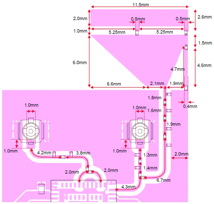
The following is the design of the EVB used for the test.
50-ohm line(microstrip line length) and Trace Antenna(Type2EL_Antenna)
Certification tests are conducted in the following patterns.
- The 50ohm microstrip line and Type2EL_Antenna need to be copied when the module is installed in the End product.
- DIGI provides set makers with Gerber data or something similar.
About the Trace antenna and feed line of the jig where the certification test was conducted
Substrate type name of certification test jig: P2ML10229
- feed line width: 0.4mm
- Substrate thin: 0.8 ± 0.1 mm
- Substrate material: FR -4
- Substrate thickness between GND layer and surface layer: 0.235mm
Layout Guidance for Microstrip Design and External Antenna
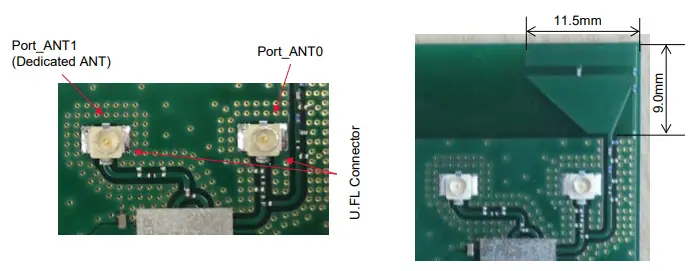
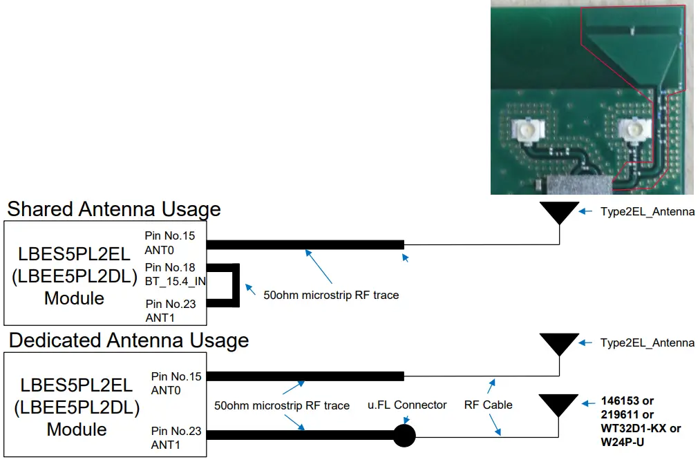
About Trace antenna(Type2EL_Antenna)
- The LBES5PL2EL (LBEE5PL2DL) module is certified with a PCB antenna(Type2EL_Antenna). The following precautions should be taken when using this PCB antenna(Type2EL_Antenna). Type2EL_Antenna can only be used for the port_ANT0 side.
- When the module is installed in the final product, the 50-ohm microstrip line and Type2EL_Antenna, outlined in right red, must be copied to the state shown in the photo below where it was certified.
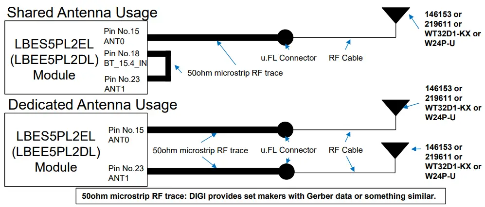
- Port_ANT1 can use the following four antennas when it is in Dedicated Usage.
146153, 219611, WT32D1-KX, W24P-U
DIGI provides set makers with Gerber data or something similar.
Layout Guidance for Microstrip Design and External Antenna
- About Antenna with uFL connector and cables and feed lines (146153, 219611, WT32D1-KX, W24P-U).
- The LBES5PL2EL (LBEE5PL2DL) module is certified with four external antenna.
- The external antenna should be connected to the LBES5PL2EL (LBEE5PL2DL) module using a 50ohm microstrip RF trace and a U.FL RF connector as shown below.
- The microstrip RF trace and U.FL connector are placed on the customer‘s PCB and are external to the LBES5PL2EL (LBEE5PL2DL) module.
- The antenna is then connected to this u.FL Connector via a 50ohm RF adapter cable.
- The design of the 50ohm microstrip RF trace on the customer’s PCB is crucially important.
- Compliant operation of the LBES5PL2EL (LBEE5PL2DL) module is dependent on the proper construction of this 50ohm line and the following guidelines must be followed to ensure legal operation of the product.
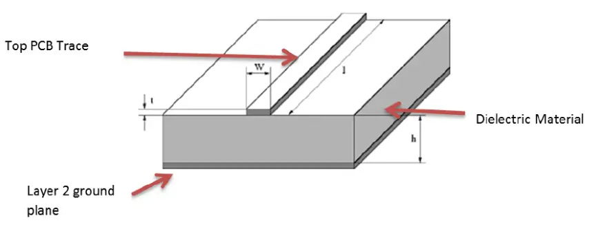
- The diagram below shows the required microstrip structure to be routed between module pins 15, 2,3, and the u.FL connector.
- The top PCB trace carries the RF energy from the module to the UFL connector.
- The Layer2 ground plane provides a return path for the circuit.
- The Dielectric material (along with the dimensions of the microstrip structures) determines the characteristic impedance of the microstrip transmission line.
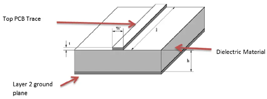
- Note the representative dimensions shown in the drawing above.
- The module customer (the integrator) must use the exact dimensions we recommend to ensure a 50-ohm impedance for this transmission line.
- The following dimensions and/or ratios should be used to set the microstrip impedance to 50o hms.
- Dielectric (PCB) Material —We recommend standard FR4 PCB material. Other dielectrics will work but will require recalculation of microstrip dimensions.
- The following guidance is predicated on the use of FR4 Dielectric.
- If FR4 is not used for PCB material, please contact DIGI to determine new dimensions for the microstrip structure.
- H (Dielectric Height) —this is the thickness of the dielectric between the trace layer (layer 1) and the ground plane on layer 2.
- Note that layer 2 must be electrical ground. We recommend a dielectric thickness of 8-15 mils.
- This range provides the customer with some flexibility in board construction.
- t (trace thickness) —Microstrip impedance is not severely affected by the thickness dimension.
- Standard 102 or 202 copper deposition is recommended. Equivalent thickness is 1-2 mils.
- W (trace width) —this is the crucial dimension. This width must be set correctly to obtain the desired 50 ohms impedance.
- When using FR-4 dielectric, the width (W) of the microstrip trace should be set to:
- W = H * 1.8
The Layer2 ground plane provides a return path for the circuit. The Dielectric material (along with the dimensions of the microstrip structures) determines the characteristic impedance of the microstrip transmission line.
- Note the representative dimensions shown in the drawing above.
- The module customer (the integrator) must use the exact dimensions we recommend to ensure a 50-ohm impedance for this transmission line.
- The following dimensions and/or ratios should be used to set the microstrip impedance to 50o hms.
- Dielectric (PCB) Material —We recommend standard FR4 PCB material. Other dielectrics will work but will require recalculation of microstrip dimensions.
- The following guidance is predicated on the use of FR4 Dielectric.
- If FR4 is not used for PCB material, please contact DIGI to determine new dimensions for the microstrip structure.
- H (Dielectric Height) —this is the thickness of the dielectric between the trace layer (layer 1) and the ground plane on layer 2.
- Note that layer 2 must be electrical ground. We recommend a dielectric thickness of 8-15 mils.
- This range provides the customer with some flexibility in board construction.
- t (trace thickness) —Microstrip impedance is not severely affected by the thickness dimension.
- Standard 102 or 202 copper deposition is recommended. Equivalent thickness is 1-2 mils.
- W (trace width) —this is the crucial dimension. This width must be set correctly to obtain the desired 50 ohms impedance.
- When using FR-4 dielectric, the width (W) of the microstrip trace should be set to:
- W = H * 1.8
Copyright © DIGI International, Inc. All rights reserved.
Documents / Resources
 |
DIGI LBES5PL2EL Communication Module [pdf] User Manual LBES5PL2EL, LBES5PL2EL Communication Module, Communication Module, Module |