![]()
![]() Digi-Key SmartFusion® 2 Maker Board
Digi-Key SmartFusion® 2 Maker Board
M2S010-MKR-KIT SmartFusion2 Maker Board
Digi-Key SmartFusion2 Maker Board
Kit Contents—M2S010-MKR-KIT
| Qty | Description |
| 1 | Digi-Key Maker Board |
| 1 | Quick start card |
Digi-Key SmartFusion® 2 Maker Board
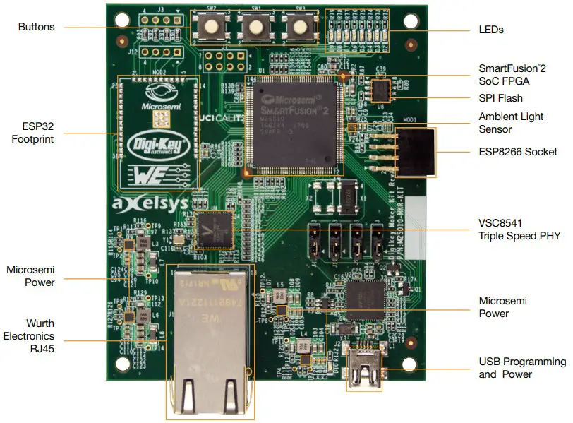
Digi-Key’s Maker Board provides designers with a low-cost evaluation board to access the SmartFusion2 system-on-chip (SoC) FPGA. This device integrates a 12K LE flash-based FPGA fabric, a 166 MHz ARM Cortex-M3 processor, DSP blocks, SRAM, eNVM, and general purpose GPIO interfaces all on a single chip.
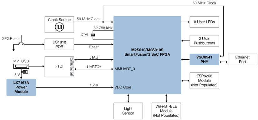
The Digi-Key SmartFusion2 Maker Board (M2S010-MKR-KIT) supports a USB port for JTAG programming, UART communications, and powering the board. The board also features an SPI flash, a 50 MHz clock source, 8 user LEDS, 2 user pushbuttons, a light sensor, and the VSC8541 PHY for 100 Mbps/1 Gbps Ethernet. There are also two unpopulated laid out connections—these pinouts support an ESP8266 and an ESP32 Wi-Fi/Bluetooth module (not included). The pinout is set up for programming and communication to the SmartFusion2 SoC FPGA. The board can be used with Microsemi’s Libero SoC v11.8 software or more recent versions of it. SoftConsole, an IDE for C/C++ programming of the ARM Cortex-M3 is available. The kit is powered through an LX7167A power module and includes integrated FlashPro5 programming hardware.
Microsemi Corporation (Nasdaq: MSCC) offers a comprehensive portfolio of semiconductor and system solutions for aerospace & defense, communications, data center and industrial markets Products include highperformance and radiation-hardened analog mixed-signal integrated circuits, FPGAs, SoCs and ASICs; power management products; timing and synchronization devices and precise time solutions, setting the world’s standard for time; voice processing devices; RF solutions; discrete components; enterprise storage and communication solutions, security technologies and scalable anti-tamper products; Ethernet solutions; Powerover-Ethernet ICs and midspans; as well as custom design capabilities and services. Microsemi is headquartered in Aliso Viejo, California and has approximately 4,800 employees globally. Learn more at www.microsemi.com.
Microsemi makes no warranty, representation, or guarantee regarding the information contained herein or the suitability of its products and services for any particular purpose, nor does Microsemi assume any liability whatsoever arising out of the application or use of any product or circuit. The products sold hereunder and any other products sold by Microsemi have been subject to limited testing and should not be used in conjunction with mission-critical equipment or applications. Any performance specifications are believed to be reliable but are not verified, and Buyer must conduct and complete all performance and other testing of the products, alone and together with, or installed in, any end-products. Buyer shall not rely on any data and performance specifications or parameters provided by Microsemi. It is the Buyer’s responsibility to independently determine suitability of any products and to test and verify the same. The information provided by Microsemi hereunder is provided “as is, where is” and with all faults, and the entire risk associated with such information is entirely with the Buyer. Microsemi does not grant, explicitly or implicitly, to any party any patent rights, licenses, or any other IP rights, whether with regard to such information itself or anything described by such information. Information provided in this document is proprietary to Microsemi, and Microsemi reserves the right to make any changes to the information in this document or to any products and services at any time without notice.
Pin Labels
LEDs (Red)
| Function | FPGA Pin | Pin Name | Level |
| LED0 | 117 | DDRIO37NB0 | Active Low |
| LED1 | 118 | DDRIO37PB0 | Active Low |
| LED2 | 122 | DDRIO43NB0 | Active Low |
| LED3 | 123 | DDRIO43PB0 | Active Low |
| LED4 | 124 | DDRIO44NB0 | Active Low |
| LED5 | 125 | DDRIO44PB0 | Active Low |
| LED6 | 128 | DDRIO47NB0 | Active Low |
| LED7 | 129 | DDRIO47PB0 | Active Low |
Push Buttons
| Function | FPGA Pin | Pin Name |
| USER_PB1 | 143 | DDRIO59PB0/GB0 |
| USER_PB2 | 144 | DDRIO63PB0 |
ESP8266 Module
| Pin Number | Function | FPGA Pin | Pin Name |
| 2 | TXO | 83 | MSIO1NB2/USB_DIR_B |
| 3 | GPIO2 | 81 | MSIO0NB2/USB_DATA7_B |
| 4 | CHPD | 90 | MSIO3NB2/USB_DATA1_B |
| 5 | GPIO0 | 93 | MSIO5NB2/USB_DATA5_B |
| 6 | RST | 88 | MSIO3PB2/USB_DATA0_B |
| 7 | RXI | 82 | MSIO1PB2/USB_XCLK_B |
ESP32 Wi-Fi-BT-BLE Module
| Pin Number | Function | FPGA Pin | Pin Name |
| 3* | BT_EN | 19 | MSIO79NB7 |
| 6 | IO34 | 8 | MSIO71PB7 |
| 7 | IO35 | 9 | MSIO72NB7 |
| 24 | IO2 | 20 | MSIO79PB7/GB1 |
| 25 | IO0 | 7 | MSIO71NB7 |
| 30 | IO18 | 10 | MSIO73NB7 |
| 31 | IO19 | 13 | MSIO76NB7 |
| 34* | RXD0 | 4 | MSIO67PB7 |
| 35* | TXD0 | 3 | MSIO67NB7 |
| 36 | IO22 | 14 | MSIO76PB7 |
| 37 | IO23 | 15 | MSIO77NB7 |
*Set jumpstart to Wi-Fi module to activate pin.
Software and Licensing
Libero® SoC Design Suite offers high productivity with its comprehensive, easy-to-learn, easyto-adopt development tools for designing with Microsemi’s low power Flash FPGAs and SoC.
The suite integrates industry standard Synopsys Synplify Pro® synthesis and Mentor Graphics ModelSim® simulation with best-in-class constraints management and debug capabilities.
Download the latest Libero SoC release
www.microsemi.com/products/fpga-soc/design-resources/design-software/liberosoc#downloads
Generate a Libero SoC Silver license for your board
www.microsemi.com/products/fpga-soc/design-resources/licensing
Download the SoftConsole IDE installation files for Linux and Windows at
www.microsemi.com/products/fpga-soc/design-resources/design-software/softconsole#downloads
Documentation Resources
For more step by step instructions about the Digi-Key Maker board, including user’s guides, tutorials, and design examples, see the documentation at www.digikey.com/smartfusion2-makerboard
Included Demo Design
When the Digikey SmartFusion2 Maker Board is powered on, all 8 LEDs will flash on and off repeatedly. Once user button 1 is pressed, the ambient light sensor will be continuously read.
The result of the light sensor reading will be shown visually across the 8 LEDs as a bar graph.
Board Schematic
![]()
Documents / Resources
 |
Digi-Key M2S010-MKR-KIT SmartFusion2 Maker Board [pdf] User Guide M2S010-MKR-KIT SmartFusion2 Maker Board, M2S010-MKR-KIT, SmartFusion2 Maker Board, Maker Board, Board |