![]() Report Logger Manual
Report Logger Manual
Quick Start: V7 031714
RL200 USB Temperature Report Logger
- The USB connector is on the end of the case under the smooth cap without the Dickson logo. Grip the cap top and bottom and pull to remove the cap. Connect logger to any Windows XP, Vista, 7 or 8 PC via a powered USB port. Do not push down on the Start button when connecting the logger to USB.
- Logger LED will remain solid green while connected via USB
AutoPlay window will open. If the AutoPlay window does not open, go to My Computer or Computer and look for a Removable Disk drive. Double click on the Removable Disk to open
- Click “Open folder to view files”

- Click DataLogger – Report Logger Graph will open.
Type a description of the materials being monitored and any other critical information in the notes field and click “Save Notes”
- Select Logging Time
Click Settings to open Select New Logging Time window.
Available Sample Intervals associated with each Logging Time are displayed. Select Logging time and click on Save to apply.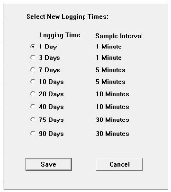
- A pop up window confirms the Logging Time selected and that the logger has been cleared

Click OK. Your settings will be saved and the program will close.
Remove logger from USB connection and replace the cap. Note that the LED turns off. The LED will remain off until the PTS button is pressed to activate logging.
Be careful not to press down on the Start button when removing from USB. If the logger LED remains solid green after removing from USB, the battery must be removed to reset the logger.
To start logging, remove cap and press and hold down on the Start button until the LED flashes Green (a pen tip or paperclip may be required to press the button). Replace cap. The LED will remain off while logging. The report logger is now logging.
NOTE: Pressing the Start button again will not stop logging. Once started the logger will continue logging until full or cleared. See below for LED operation description.
Viewing Logged Data
Per the quick start instructions above, connect the logger to a PC via USB and click “DataLogger.exe” to open the graph. Logged data will be plotted on the logger graph.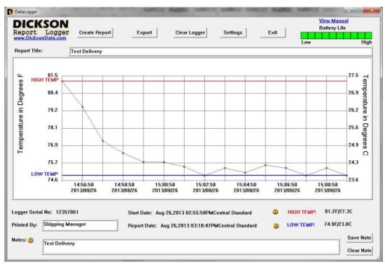 The graph can be saved in the following ways:
Create Report – exports graph and data summary to a .pdf file (see below)
Export – 3 options
Save data as a CSV comma delimited data file
Save a .jpg of the graph
Save a .pdf of the graph
Sample Report

Once the graph has been printed or exported, select CLEAR LOGGER to clear the logger of all saved data. Logger can now be removed from USB and the cap replaced.
To start logging, remove cap and press and hold down on the Start button until the LED flashes Green (a pen tip or paperclip may be required to press the button). Replace cap. The LED will remain off while logging. The report logger is now logging.
Logger Features / Specifications
Logging Time: Set Logging Time via the Settings button in the logger interface. Total time logger will save data before it is full. Logger will stop logging when full.
Sample Interval: Determined by Logging Time selected. Ranges from 1 Minute to 30 Minutes
Ambient Operating Conditions: -30 to 176F (-35 to 80C); 0 to 100% RH.
Unit of Measure: Graph displays saved data in F & C.
Temperature Accuracy: +/-1.8F (1.0C) from 40 to 90F (4 to 32C) (non condensing), +/- 2.3F (1.3C) Remaining
PC Requirements: Windows XP, Vista or 7, 1 available USB port
Weight: 1.6 oz (45.356 grams)
Dimensions: 5.5″ x 1″ x 1.2″ (13.97cm x 2.45cm x 3.048cm)
IP Rating: 63 (Occasional re-application of silicone grease around the inside edge of each end cap is recommended to prevent water ingress).
Power
Battery: 2/3 Lithium 3.6V Photo Battery – User Replaceable
Battery Life: Minimum battery life is one logging period at minimum specified operating temperature. Check the battery life indicator, on graph, before each use.
Replacing Battery: Remove cap on battery end of case by gripping the top and bottom of the cap with the Dickson logo and pulling. The logger will need to be connected to the PC and cleared before logging can begin.
LED Operation
When connected to a PC via USB:
Green solid = connected via USB (If LED remains solid green after being removed from USB, remove battery from logger to reset or battery will drain in a couple of days.)
Red solid = connected via USB and battery is low
When PTS button is pressed:
Green Blink – Logger logging – Battery power level good
Red Blink – Logger logging – Low battery power.
Off Solid – Logger is not logging – No battery power
Green Blink followed by Red Blink – Logger Full
The LED will continue to blink for as long as the PTS button is pressed. Once the user releases the PTS button, the LED will stop blinking.
Graph Features

![]()
Documents / Resources
 |
DICKSON RL200 USB Temperature Report Logger [pdf] User Manual RL200, RL200 USB Temperature Report Logger, RL200, USB Temperature Report Logger, Temperature Report Logger, Report Logger, Logger |