DFI VC300-CS In Vehicle Embedded System

Package Contents
- 1 VC300-CS System Unit
- 1 Mounting Bracket
- 1 Power Connector
 Product Overview
Front View
- COM2
- COM1
- DIO
- LAN2
- LAN1
- USB3.0
- VGA
- PoE4
- DC-in 9~36V
- Grounding
- PoE3
- PoE2
- PoE1
- LAN Power (Red) PoE Power (Green)
- Antenna Hole

Rear View
- Reset Button
- SIM Sockets
- HDMI
- DP++
- USB2.0
- Status LED (Orange) HDD LED (Red)
- Line-out
- Mic-in
- Power Button
- 2.5” SSD Storage Driver Bay
- Antenna Hole

Removing the Chassis Cover
Please observe the following guidelines and follow the instructions to open the system.
- Make sure the system and all other peripheral devices connected to it have been powered off.
- Disconnect all power cords and cables.
Step 1: Turn over the machine to let the bottom side become the top.
Remove eight screws circled by red in each corner.

Step 2: Remove the bottom case

Step 3: The power part appears.

Step 4: There is 2.5” HDD slot for harddisk/SSD installation.

Step 5: If you want to change/remove/install other components, please remove the power part first. Remove the 4 screws in each corner circled by red.

Step 6: Tilt up to remove the power part carefully and slowly. Please unplug these cables first.

Step 7: The main body appears.

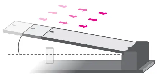
Installing an Antenna
Before installing the antenna, please make sure that the following safety cautions are wellattended.
- Make sure the PC and all other peripheral devices connected to it has been powered down.
- Disconnect all power cords and cables.
Step 1:
There are antenna holes reserved on every side of the system and covered by rubber plugs.
Please remove the plug prior to installing an antenna.


Step 2:
Connect the internal cable to the board’s antenna connector, screw the antenna connector through the antenna hole with washers and nuts, and screw on the antenna as illustrated below.

Inserting a 2.5″ HDD/SDD
The drive bay can be easily accessed without opening the system.
Before inserting a HDD/SDD, please turn off the system first.
Use the following procedure to install a SATA HDD or SSD to the system:
Step 1:
Locate the drive bay on the front.

Step 2:
Pull the silver latch to unlock the door.
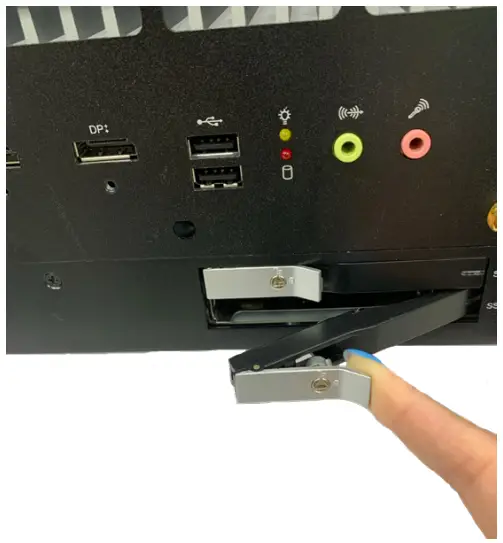
Step 3:
Slide the drive into the slot until the drive is fully seated.
Close the drive latch to lock the drive in place.

![]() Important:
Important:
Excessive force may damage its mechanical parts.
If the HDD/SSD is inserted backward into the slot, forcing the device may damage the slot.
Installing the M.2 Module
Before installing the M.2 module into the M.2 socket, please make sure that the following safety cautions are well-attended.
- Make sure the PC and all other peripheral devices connected to it has been powered down.
- Disconnect all power cords and cables.
- Locate the M.2 socket on the system board
- Make sure the notch on card is aligned to the key on the socket.
- Make sure the standoff screw is removed from the standoff.


Please follow the steps below to install the card into the socket.
Step 1:
Insert the card into the socket at an angle while making sure the notch and key are perfectly aligned.
Step 2:
Press the end of the card far from the socket down until against the stand-off.
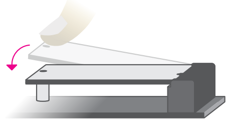
Step 3:
Screw tight the card onto the stand-off with a screw driver and a stand-off screw until the gap between the card and the stand-off closes up. The card should be lying parallel to the board when it’s correctly mounted.
Installing the SO-DIMM Module
Before installing the memory module, please make sure that the following safety cautions are well-attended.
- Make sure the PC and all other peripheral devices connected to it has been powered down.
- Disconnect all power cords and cables.
- Locate the SO-DIMM socket on the system board
- Make sure the notch on memory card is aligned to the key on the socket.

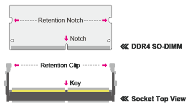
Please follow the steps below to install the memory card into the socket.
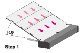
Step 1:
Insert the memory card into the slot while making sure 1) the notch and the key are aligned, and 2) the non-connector end rises approximately 45 degrees horizontally. Press the card firmly into the socket while applying and maintaining even pressure on both ends.
Step 2:
Press the end of the card far from the socket down while making sure the retention notch and the clip align as indicated by the dotted line in the illustration. If the retention notch and the clip do not align, please remove the card and re-insert it. Press the card all the way down.

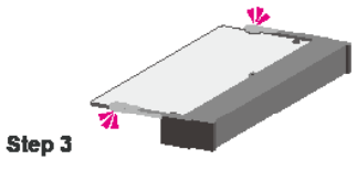
Step 3:
The clips snap automatically and abruptly to the retention notches of the card sounding a distinctive click, and lock the card in place. Inspect that the clip sits in the notch. If not, please pull the clips outward, release and remove the card, and mount it again.
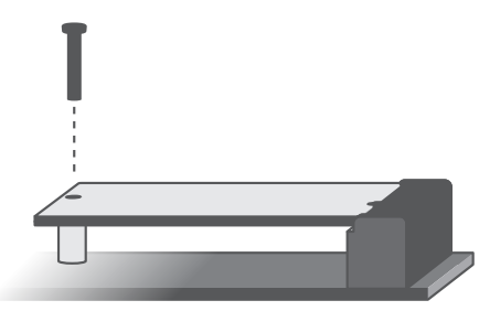
Mounting Options
The wall mount kit containing two mounting brackets can be attached to the bottom of the system for mounting onto desired locations, such as walls, stands, or shelves. Locate the mounting holes on the bottom of the system as shown in the photo. Screw on the two brackets onto the system with six screws as illustrated below.


Customer Support
![]() DFI reserves the right to change the specifications at any time prior to the product’s release. This QR may be based on the product’s revision. For more documentation and drivers, please visit the download page at www.dfi.com/ downloadcenter, or via the QR codes to the right.
DFI reserves the right to change the specifications at any time prior to the product’s release. This QR may be based on the product’s revision. For more documentation and drivers, please visit the download page at www.dfi.com/ downloadcenter, or via the QR codes to the right.

In-Vehicle Embedded System
www.dfi.com
Documents / Resources
 |
DFI VC300-CS In Vehicle Embedded System [pdf] Installation Guide VC300-CS In Vehicle Embedded System, VC300-CS, In Vehicle Embedded System, Vehicle Embedded System, Embedded System |