DFI M.2-COM4 M.2 Serial Port Module
Product Specifications
- Product Name: M.2-COM4
- Type: M.2 Serial Port Module
Product Information
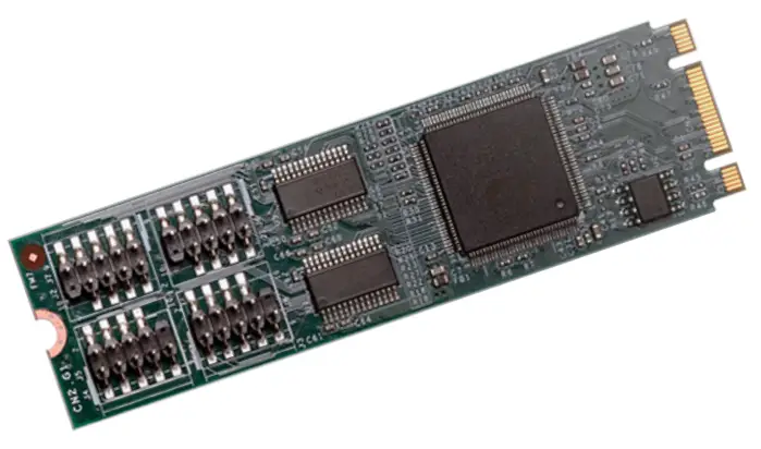
The M.2-COM4 is a serial port module designed for use in computer systems. It provides additional serial port connectivity for enhanced functionality.
Product Hardware Installation
- Before installing the M.2-COM4 module, ensure you have the necessary internal components.
- Handle the module with care to avoid damage from static electricity.
- Follow the installation instructions provided in the user manual to securely install the module in your system.
ProductStatic Electricity Precautions
- Keep the M.2-COM4 module in its anti-static bag until ready for installation.
- Wear an antistatic wrist strap during handling to prevent electrostatic discharge.
- Work on a static-free surface and handle the module only by its edges.
- Avoid touching the pins or contacts and hold connectors by their ends to prevent ESD damage.
- If possible, work at an ESD workstation or connect to the system chassis for protection.
FAQ
What should I do if any items are missing or damaged from the package?
In case of missing or damaged items, please contact your dealer or sales representative for assistance in resolving the issue.
Copyright
- This publication contains information that is protected by copyright. No part of it may be reproduced in any form or by any means or used to make any transformation/adaptation without prior written permission from the copyright holders.
- This publication is provided for informational purposes only. The manufacturer makes no representations or warranties concerning the contents or use of this manual and specifically disclaims any express or implied warranties of merchantability or fitness for any particular purpose. The user will assume the entire risk of the use or the results of the use of this document. Further, the manufacturer reserves the right to revise this publication and make changes to its contents at any time, without obligation to notify any person or entity of such revisions or changes.
- Changes after the publication’s first release will be based on the product’s revision. The website will always provide the most updated information.
- © 2020. All Rights Reserved.
Trademarks
Product names or trademarks appearing in this manual are for identification purposes only and are the properties of the respective owners.
FCC and DOC Statement on Class B
This equipment has been tested and found to comply with the limits for a Class B digital device, under Part 15 of the FCC rules. These limits are designed to provide reasonable protection against harmful interference when the equipment is operated in a residential installation. This equipment generates, uses, and can radiate radio frequency energy and, if not installed and used by the instruction manual, may cause harmful interference to radio communications. However, there is no guarantee that interference will not occur in a particular installation. Suppose this equipment does cause harmful interference to radio or television reception, which can be determined by turning the equipment off and on. In that case, the user is encouraged to try to correct the interference by one or more of the following measures:
- Reorient or relocate the receiving antenna.
- Increase the separation between the equipment and the receiver.
- Connect the equipment to an outlet on a circuit different from that to which the receiver is connected.
- Consult the dealer or an experienced radio TV technician for help.
Notice:
- The changes or modifications not expressly approved by the party responsible for compliance could void the user’s authority to operate the equipment.
- Shielded interface cables must be used to comply with the emission limits.
About this Manual
This manual can be downloaded from the website, or acquired as an electronic file included in the optional CD/DVD. The manual is subject to change and update without notice and may be based on editions that do not resemble your products. Please visit our website or contact our sales representatives for the latest editions.
Warranty
- Warranty does not cover damages or failures that arise from misuse of the product, inability to use the product, unauthorized replacement, or alteration of components and product specifications.
- The warranty is void if the product has been subjected to physical abuse, improper installation, modification, accidents, or unauthorized repair.
- Unless otherwise instructed in this user’s manual, the user may not, under any circumstances, attempt to perform service, adjustment, or repairs on the product, whether in or out of warranty. It must be returned to the purchase point, factory or authorized service agency for all such work.
- We will not be liable for any indirect, special, incidental, or consequential damages to the product that has been modified or altered.
About the Package
The package contains the following items. If any of these items are missing or damaged, please contact your dealer or sales representative for assistance.
One M.2-COM4 Module
Optional Item
Converter cable, pin headers to DB9, Length = 250mm
Before Using the System Board
When installing the system board in a new system, you will need at least the following internal components.
Host system with M.2 M or B key socket
Static Electricity Precautions
It is quite easy to inadvertently damage your PC, system board, components, or devices even before installing them in your system unit. Static electrical discharge can damage computer components without causing any signs of physical damage. You must take extra care in handling them to ensure against electrostatic build-up.
- To prevent electrostatic build-up, leave the system board in its anti-static bag until you are ready to install it.
- Wear an antistatic wrist strap.
- Do all preparation work on a static-free surface.
- Hold the device only by its edges. Be careful not to touch any of the components, contacts, or connections.
- Avoid touching the pins or contacts on all modules and connectors. Hold modules or connectors by their ends.
Important:
Electrostatic discharge (ESD) can damage your processor, disk drive, and other components. Perform the upgrade instruction procedures described at an ESD workstation only. If such a station is not available, you can provide some ESD protection by wearing an antistatic wrist strap and attaching it to a metal part of the system chassis. If a wrist strap is unavailable, establish and maintain contact with the system chassis throughout any procedures requiring ESD protection.
Safety Measures
- To avoid damage to the system, use the correct AC input voltage range.
- To reduce the risk of electric shock, unplug the power cord before removing the system chassis cover for installation or servicing. After installation or servicing, cover the system chassis before plugging the power cord.
Introduction
Specifications
- I/O CONNECTORS RS232/RS422/RS485 functions with DB9 connector.
- POWER INPUT 3.3V via M.2 connector
- COMPATIBLE MODELS All DFI systems and boards with M.2 interface
- TEMPERATURE
- Operating: -40oC to 85oC
- Storage: -40oC to 85oC
- HUMIDITY 5% to 90%
- FORM FACTOR M.2 B-M Key 22mm x 80mm (4 ports)
- REGULATION CE/FCC class B/RoHS
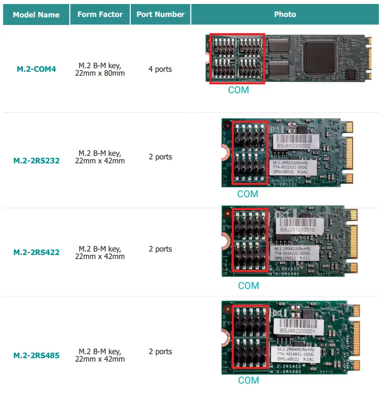
Other models
Hardware Installation
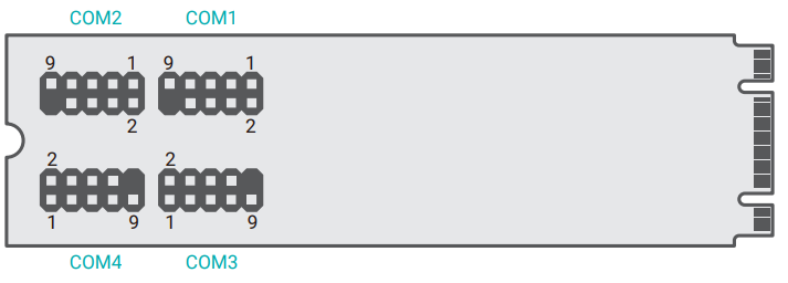
Module Layout
Pin headers for the four COM (serial) ports are located on the top side of the M.2 B+M Key 22mm x 80mm module. Cables or converter cables may be required for connection to your terminal devices.
Important:
Electrostatic discharge (ESD) can damage your board, processor, disk drives, add-in boards, and other components. Perform installation procedures at an ESD workstation only. If such a station is not available, you can provide some ESD protection by wearing an antistatic wrist strap and attaching it to a metal part of the system chassis. If a wrist strap is unavailable, establish and maintain contact with the system chassis throughout any procedures requiring ESD protection.
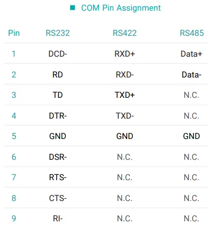
Pin Assignment
The serial ports are asynchronous communication ports with 16C550A-compatible UARTs that can be used with modems, serial printers, remote display terminals, and other serial devices.
Serial Mode Setting
Configure the serial mode of the COM ports in the Device Manager.
M.2 Installation
Before installing the M.2 module into the M.2 socket, please make sure that the following safety cautions are well-attended.
- Make sure the PC and all other peripheral devices connected to it have been powered down.
- Disconnect all power cords and cables.
- Locate the M.2 socket on the system board
- Make sure the notch on the card is aligned to the key on the socket.
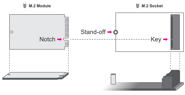
Please follow the steps below to install the card into the socket.
- Step 1:
Insert the card into the socket at an angle while making sure the notch and key are perfectly aligned.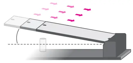
- Step 2:
Press the end of the card far from the socket down until against the stand-off.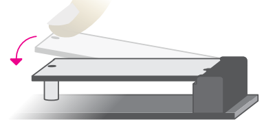
- Step 3:
Screw tight the card onto the stand-off with a screwdriver and a stand-off screw until the gap between the card and the stand-off closes up. The card should be lying parallel to the board when it’s correctly mounted.
Software
Install drivers, utilities, and software applications that are required to facilitate and enhance the performance of the system board. You may acquire the software from your sales representatives, from an optional DVD included in the shipment, or from the website download page at https://www.dfi.com/DownloadCenter.
Auto-run Menu
After inserting your DVD-ROM into your optical drive or executing your DVD image, the System Utility auto-run menu may pop up. Click on the utility or driver that is to be installed on the system. Please refer to the following sections that correspond to your selection for more information.
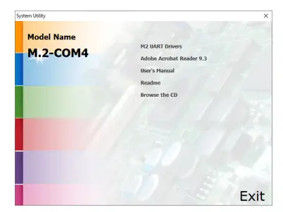
Note:
This step can be ignored if the applications are downloaded as standalone files.
M.2 UART Drivers
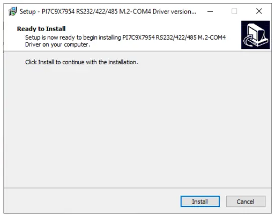
- The setup is ready to install the utility. Click “Install”.
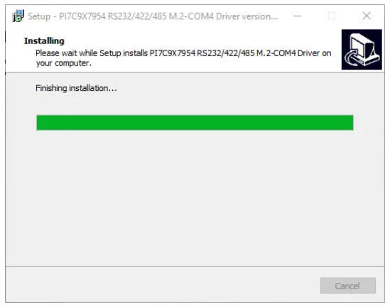
- The setup is in progress. Please wait for a moment.
- Installation is complete. Please restart the system before using
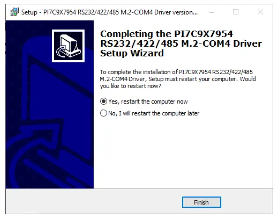
Note: the COM ports.
Serial Mode Configuration
- Boot the system into Windows OS.
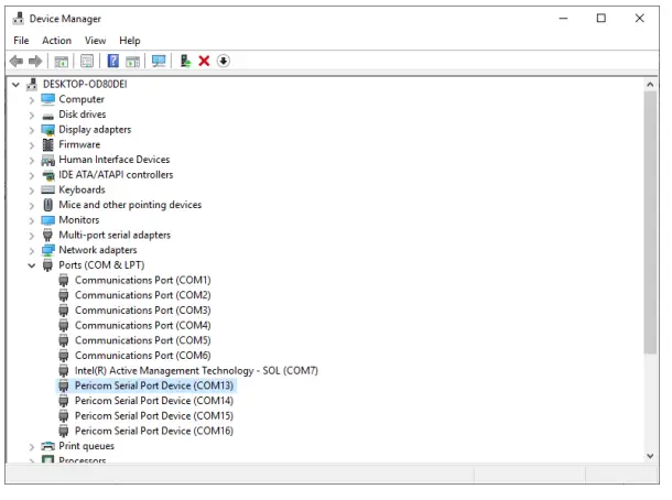
- Go to Device Manager by right-clicking the “Start” icon, and click “Device Manager” .

- Find “Ports (COM&LPT)” in the list and expand it. Locate the COM ports that are named “Pericom Serial Port Device”.
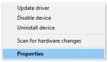
- Right-click on the port and select “Properties”.
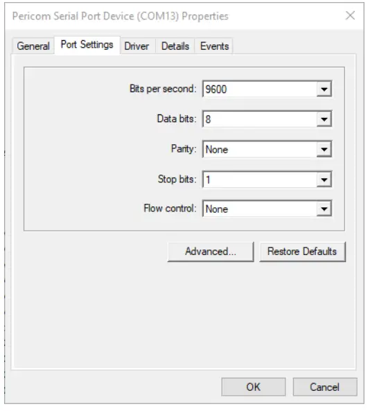
- Go to the tab “Port Settings”. Configure the terminal communication settings to match those of the terminal device. Click “OK” to save the settings., or click “Restore Defaults” to reset the port to default settings.
- Bits per second 110, 300, 600, 1200, 2400, 4800, 9600, 14400, 19200, 38400, 57600, 56000, 115200, 128000, 230400, 256000, 460800, 921600
- Data bits 4, 5, 6, 7, 8
- Parity Even, Odd, None, Mark, Space
- Stop bits 1, 1.5, 2
- Flow control Xon/Xoff, Hardware, None
- Click “Advanced” to bring out additional settings.
- Click “COM Port Number” to choose which COM port is to be configured.
- Configure the buffer to correct communication speed when abnormality occurs.
Click “Transceiver Type” to change serial mode — RS232, RS422, RS485-4W, RS485-2W.
Note: 4W = Four wires; 2W = Two wires - Click “OK” to save the settings, or click “Defaults” to reset to default settings.

Documents / Resources
 |
DFI M.2-COM4 M.2 Serial Port Module [pdf] User Manual M.2-COM4 M.2 Serial Port Module, M.2-COM4, M.2 Serial Port Module, Serial Port Module, Module |


