1. Einleitung
This manual provides detailed instructions for the installation, operation, and maintenance of your GAMEMAX Master M905 ATX Full Tower Computer Case. Please read this manual thoroughly before beginning assembly to ensure proper setup and safe usage. This computer case is designed to accommodate ATX motherboards and offers ample space for high-performance components and advanced cooling solutions.
2. Sicherheitshinweise
- Always disconnect the power supply from the wall outlet before installing or removing any components to prevent electrical shock.
- Handle internal components with care. Avoid touching circuit boards directly; hold them by their edges.
- Wear an anti-static wrist strap when handling sensitive electronic components to prevent electrostatic discharge (ESD) damage.
- Kleinteile und Schrauben von Kindern fernhalten.
- Ensure proper ventilation around the computer case to prevent overheating.
3. Packungsinhalt
Bitte überprüfen Sie, ob alle unten aufgeführten Artikel in Ihrem Paket enthalten sind:
- GAMEMAX Master M905 ATX Full Tower Computer Case
- Accessory Box (containing screws, standoffs, cable ties, and user manual)
- Pre-installed cooling fans (quantity may vary by model variant)
4. Komponentenidentifikation
Familiarize yourself with the various parts of the GAMEMAX Master M905 case.

Abbildung 4.1: Vorne links view of the GAMEMAX Master M905 case, showcasing the tempered glass side panel and the front mesh panel with two illuminated blue fans. The top panel features front I/O ports.

Abbildung 4.2: Top-front perspective of the case, showing the top ventilation grille and the front I/O panel which includes USB 2.0 and USB 3.0 ports, audio jacks, and power/reset buttons.
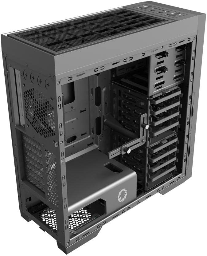
Abbildung 4.3: Intern view of the case, illustrating the spacious interior with multiple drive bays, the motherboard mounting area, and the dedicated power supply shroud at the bottom.
5. Installationsanleitung
5.1. Vorbereitung des Falls
- Seitenteile entfernen: Locate the thumbscrews on the rear of the case. Unscrew them and carefully slide off the tempered glass side panel and the solid steel side panel. Set them aside on a soft, non-abrasive surface.
- Zubehörbox: Locate the accessory box inside the case, usually secured in a drive bay. This box contains all necessary screws, standoffs, and cable ties for installation.
5.2. Motherboard-Installation
- Abstandshalter installieren: Identify the correct standoff locations for your ATX motherboard. The Master M905 typically has pre-installed standoffs for ATX. If not, install them using the provided tool.
- I/O-Blende installieren: Snap your motherboard's I/O shield into the opening at the rear of the case from the inside. Ensure it is securely seated.
- Motherboard montieren: Carefully align your motherboard with the standoffs and the I/O shield. Gently lower the motherboard into place.
- Motherboard sichern: Use the provided motherboard screws to secure the motherboard to the standoffs. Do not overtighten.
5.3. Installation des Netzteils (PSU)
- Position PSU: The Master M905 supports bottom-mounted PSUs. Slide your PSU into the designated compartment at the bottom rear of the case, ensuring the fan faces downwards (if the case has a bottom vent) or upwards.
- Sicheres Netzteil: Align the PSU with the screw holes at the rear of the case. Secure it with the provided PSU screws.
5.4. Installation des Speichermediums (HDD/SSD)
The case supports various drive configurations. Refer to the internal layout for specific bay types.
- 3.5"-Festplatten: Typically installed in tool-less drive cages or trays. Slide the HDD into a tray and secure it with clips or screws.
- 2.5"-SSDs: Can be mounted on dedicated SSD brackets behind the motherboard tray or in 3.5" drive trays using adapter screws.
5.5. Installation der Erweiterungskarte (PCIe)
- Steckplatzabdeckungen entfernen: Unscrew or remove the necessary PCIe slot covers from the rear of the case corresponding to your motherboard's PCIe slots.
- Installationskarte: Carefully insert your expansion card (e.g., graphics card) into the appropriate PCIe slot on the motherboard until it clicks into place.
- Sichere Karte: Secure the expansion card to the case with the provided screws.
5.6. Installation des Frontplattenanschlusses
Connect the front panel cables from the case to the corresponding headers on your motherboard. Consult your motherboard manual for exact header locations.
- USB 2.0/3.0: Schließen Sie die USB-Kabel an die USB-Anschlüsse des Motherboards an.
- Audio: Schließen Sie das HD-Audiokabel an den Audioanschluss des Motherboards an.
- Ein-/Ausschalter/Reset/LEDs: Connect the small individual cables (Power SW, Reset SW, HDD LED, Power LED) to the front panel header pins on your motherboard. Pay close attention to polarity for LEDs.
5.7. Kabelmanagement
Nutzen Sie die Kabeldurchführungen und Befestigungspunkte hinter dem Mainboard-Tray, um die Kabel ordentlich zu verlegen. Dies verbessert die Luftzirkulation und die Optik.
6. Bedienung
6.1. Einschalten
Once all components are installed and cables are connected, replace the side panels. Connect your monitor, keyboard, mouse, and power cable to the PSU. Press the power button on the front panel to start your system.
6.2. Frontseitige E/A-Anschlüsse
Die Frontblende ermöglicht einen bequemen Zugriff auf:
- USB 2.0 Ports: For connecting peripherals like keyboards, mice, and older USB devices.
- USB 3.0 Ports: Für Hochgeschwindigkeits-Datenübertragung mit kompatiblen Geräten.
- Audiobuchsen: Zum Anschließen von Kopfhörern und Mikrofonen.
- Netzschalter: Zum Ein-/Ausschalten des Systems.
- Reset-Taste: Um das System neu zu starten.
7. Wartung
7.1. Reinigung
Regular cleaning helps maintain optimal performance and extends the lifespan of your components.
- Exterieur: Wischen Sie die Außenflächen mit einem weichen, damp Tuch. Vermeiden Sie aggressive Chemikalien.
- Innere: Use compressed air to remove dust from fans, heatsinks, and other components. Perform this outdoors or in a well-ventilated area.
7.2. Wartung des Staubfilters
The Master M905 case is equipped with dust filters to prevent dust buildup. Regularly clean these filters:
- Locate and remove the dust filters (e.g., front, top, bottom PSU intake).
- Rinse them under running water or use a soft brush to remove accumulated dust.
- Stellen Sie sicher, dass die Filter vollständig trocken sind, bevor Sie sie wieder einsetzen.
8. Fehlerbehebung
Sollten Probleme auftreten, beachten Sie bitte die folgenden grundlegenden Schritte zur Fehlerbehebung:
- System schaltet sich nicht ein: Check all power connections, including the PSU to the wall, the 24-pin ATX connector, and the 8-pin CPU power connector to the motherboard. Ensure the front panel power switch cable is correctly connected to the motherboard.
- Lüfter drehen sich nicht: Verify that all fan cables are securely connected to the motherboard fan headers or a fan controller.
- USB-Anschlüsse funktionieren nicht: Ensure the front panel USB cables are correctly connected to the motherboard's USB headers.
- Keine Bildausgabe: Confirm that your graphics card is properly seated in its PCIe slot and that all necessary power cables are connected to it. Ensure your monitor cable is connected to the graphics card, not the motherboard's integrated graphics ports (unless you are using integrated graphics).
9. Spezifikationen
| Besonderheit | Spezifikation |
|---|---|
| Marke | GAMEMAX |
| Modell | Meister M905 |
| Gehäusetyp | Voller Turm |
| Motherboard-Kompatibilität | ATX |
| Material | Stahl, gehärtetes Glas |
| Farbe | Schwarz |
| Produktabmessungen (L x B x H) | 23.5 x 22.95 x 11.26 Zoll |
| Front I / O Ports | 2x USB 2.0, 2x USB 3.0, Audio-Ein-/Ausgang |
| Erweiterungssteckplätze | 8 |
| Kühlmethode | Luft, Wasser |
| Montageart des Netzteils | Tower (Bottom-mounted) |
10. Garantie und Support
For warranty information and technical support, please refer to the official GAMEMAX webBesuchen Sie unsere Website oder wenden Sie sich an Ihren Händler vor Ort. Bewahren Sie Ihren Kaufbeleg für Garantieansprüche auf.


