dataprobe iBoot-G2 Web Enabled Power Switch

Product Information: Web Enabled Power Switch
Congratulations on purchasing the best network controlled power switch available. The iBoot-G2 is a network attached, IP addressed, web controlled AC power switch. It features international standard IEC320 connections and is compatible with power mains worldwide. The iBoot-G2 allows you to perform power On, Off, or Power Cycle (Reboot or Power Burst) remotely using a web browser. It also supports Telnet for text commands and interfaces with other Dataprobe products and custom software development through DxP, URL, and API.
Features
- Web Based setup and control
- iBoot Cloud Service: Control all your iBoots from one web portal
- AutoPing: Automatic monitoring and action for failed equipment
- Event Scheduling for real-time power control
- Telnet setup and control
- Management Utility: Easy Setup, Firmware upgrades, and Reset to Factory Default
- Easy Software Integration: Protocols to build your own custom applications
- Local Link Multicast Name Resolution: Use to access on supporting networks
- Reboot Only Mode: Prevents accidental switching off to ensure continuous operation
- URL Control: Create your own website link for control
- API Control: Control and setup Utilizing the cloud registration
Specifications
The iBoot-G2 is equipped with the following specifications:
- Date of Release: March 2021
- Product Model: iBoot-G2
- Product Version: iboot-g2_v210331w
- Page Count: 27
Important Safety Instructions
When using this product, please follow these important safety instructions:
- Read and understand all instructions.
- Follow all warnings and markings on the product.
- Unplug the product from the wall outlet before cleaning. Use a damp cloth for cleaning; do not use liquid cleaners or aerosol cleaners.
- Avoid using the product in outdoor environments or near water sources.
- Ensure the product is placed on a stable surface to prevent falls and damages.
- Provide proper ventilation to prevent overheating.
Product Usage Instructions
Hardware Installation
Follow the hardware installation instructions provided in the user manual to connect the iBoot-G2 to your power source. Ensure proper connections are made according to international standard IEC320.
Initial Configuration
Before using the iBoot-G2, it needs to be configured. Follow the instructions in the user manual to set up the device for your specific network requirements. This includes configuring network settings, passwords, and security levels.
Web Browser Operation
To control the iBoot-G2 using a web browser, open your preferred browser and enter the IP address or hostname of the device. Log in using your username and password. Once logged in, you can perform power On, Off, or Power Cycle (Reboot or Power Burst) operations with a click of a mouse.
Web Setup
The web setup allows you to customize various settings of the iBoot-G2 through a user-friendly interface. Follow the instructions in the user manual to access the web setup and configure features such as event scheduling, URL control, and iBoot Cloud Service integration.
iBoot Cloud Service
The iBoot Cloud Service provides a centralized web portal for controlling multiple iBoots. Refer to the user manual for instructions on how to set up and utilize the iBoot Cloud Service.
Command Line Interface
The iBoot-G2 also supports Telnet for text commands. If you prefer to use the command line interface, refer to the user manual for details on how to set up and control the device using Telnet.
Firmware Upgrades
Periodically, firmware upgrades may be available for the iBoot-G2. Follow the instructions in the user manual to upgrade the firmware of your device and access any new features or improvements.
Troubleshooting
If you encounter any issues with the iBoot-G2, refer to the troubleshooting section in the user manual. It provides solutions to common problems and helps you resolve any technical difficulties you may face. For detailed technical specifications, please refer to page 26 of the user manual. If you require further assistance or have any questions regarding the product, please contact our technical support team. The contact details can be found on page 27 of the user manual.
Congratulations on purchasing the best network controlled power switch available. The iBoot-G2 provides you the ability to reboot crashed devices with the click of a mouse. Be sure to read up on all the features of the iBoot-G2 Including:
- Web Based setup and control
- iBoot Cloud Service: Control all your iBoots from one web portal.
- AutoPing: Automatic monitoring and action for failed equipment.
- Event Scheduling for real-time power control.
- Telnet setup and control
- Management Utility: Easy Setup, Firmware upgrades and Reset to Factory Default.
- Easy Software Integration: Protocols to build your own custom applications.
- Local Link Multicast Name Resolution: Use to access on supporting networks.
- Reboot Only Mode: Prevents accidental switching off to ensure continuous operation.
- URL Control: Create your own website link for control.
- API Control: Control and setup Utilizing the cloud registration
* API protocol is detailed in a separate document

Important Safety Instructions
When using this product, basic safety precautions should always be followed to reduce the risk of fire, electric shock, and injury to persons, including the following:
- Read and understand all instructions.
- Follow all warnings and marked on the product.
- Unplug this product from the wall outlet before cleaning. Do not use liquid cleaners or aerosol cleaners. Use a damp cloth for cleaning.
- Do not use this product in an outdoor environment or near water, for example, near a bath tub, wash bowl, kitchen sink, or laundry tub, in a wet basement, or near a swimming pool.
- Do not place this product on an unstable cart, stand, or table. The product may fall, causing serious damage to the product.
- Slots and openings in this product and the back or bottom are provided for ventilation to protect it from overheating; these openings must not be blocked or covered. The openings should never be blocked by placing the product on the bed, sofa, rug, or other similar surface. This product should never be placed near or over a radiator or heat register. This product should not be placed in a built-in installation unless proper ventilation is provided.
- This product should be operated only from the type of power source indicated on the marking label. If you are not sure of the type of power supply to your home, consult your dealer or local power company.
- This product is equipped with a three wire grounding type plug, a plug having a third (grounding) pin. This plug will only fit into a grounding type power outlet. This is a safety feature. If you are unable to insert the plug into the outlet, contact your electrician to replace your obsolete outlet. Do not defeat the safety purpose of the grounding type plug. Do not use a 3-to-2 prong adapter at the receptacle; use of this type adapter may result in risk of electrical shock and/or damage to this product.
- Do not allow anything to rest on the power cord. Do not locate this product where the cord will be abused by persons walking on it.
- Do not overload wall outlets and extension cords as this can result in the risk of fire or electric shock.
- Never push objects of any kind into this product through slots as they may touch dangerous voltage points or short out parts that could result in a risk of fire or electrical shock. Never spill liquid of any kind on the product.
- To reduce the risk of electrical shock, do not disassemble this product, but take it to a qualified serviceman when some service or repair work is required. Opening or removing covers may expose you to dangerous voltages or other risks. Incorrect re-assembly can cause electric shock when the appliance is subsequently used.
- Unplug this product from the wall outlet and refer servicing to qualified service personnel under the following conditions:
- When the power supply cord or plug is damaged or frayed.
- If liquid has been spilled into the product.
- If the product has been exposed to rain or water.
- If the product does not operate normally by following the operating instructions. Adjust only those controls that are covered by the operating instructions because improper adjustment of other controls may result in damage and will often require extensive work by a qualified technician to restore the product to normal operation.
- If the product has been dropped or has been damaged.
- If the product exhibits a distinct change in performance.
- Avoid using a telephone (other than a cordless type) during an electrical storm. There may be a remote risk of electric shock from lightning.
- Do not use the telephone to report a gas leak in the vicinity of the leak.
- Do not exceed the maximum output rating of the auxiliary power receptacle.
General Description
The iBoot-G2 is a network attached, IP addressed, web controlled AC power switch. Anyone with a web browser can access iBoot-G2 to perform power On, Off or Power Cycle (Reboot or Power Burst). iBoot-G2 access is password protected with user and administrator security levels.
iBoot-G2 features international standard IEC320 connections and is compatible with power mains worldwide. A simple Web browser interface makes it easy to control power from anywhere in the world with a click of a mouse. iBoot-G2 also supports Telnet for text commands, as well as Dataprobe’s Exchange Protocol (DxP), URL and API (utilizing Cloud) for interfacing to a variety of Dataprobe products and custom software development.

Uses for iBoot
- Remote reboot of any device, routers, servers, kiosks, etc. The device to be rebooted need not be network attached.
- Secure sensitive devices by keeping them powered off when not in use. This prevents hackers from seeing them at all times.
- Power down equipment when not needed for power savings and to save on wear and tear.
- Power up alert devices like sirens, lamps, messages; or control environmental system like heaters, coolers pumps, etc.
Multiple Control Options
In addition to the Web control capabilities, iBoot-G2 features several other means to operate automatically or under computer control.
- URL Control: You can send a single URL to the iBoot-G2 containing all the information necessary to query or change the power status. This makes it easy to create a single button on your desktop or embed into a batch file or script.
- AutoPing: The AutoPing feature allows iBoot-G2 to automatically detect failed equipment and perform a timed reboot or other power control function (like turning on an indicator or siren). You set 1 or 2 IP addresses to be periodically pinged. When iBoot-G2 no longer detects a response from the address(es), the programmed power control function is actuated.
- Telnet: iBoot’s Command Line Interface (CLI) allows direct control and setup through Telnet.
- Dataprobe Exchange Protocol (DxP): Use this status and control protocol to build custom applications to manage iBoot, or use our available utility program to build batch files or command line routines. Download DxP documentation and utilities at dataprobe.com/support-iboot-g2
- API: When iBoot-G2 is connected to a cloud account, there is an API to send control and configuration data between the cloud and the device. The API protocol is detailed in a separate document.
Hardware Installation
Ethernet Connections
iBoot-G2 supports 10/100 Ethernet using the cable supplied, or other suitable unshielded twisted pair (Cat 5) cabling. Activity (green) and 100Mb (amber) LEDs on the network connector indicate when the network connection is properly established and when the connection is 100 Mbit/s.
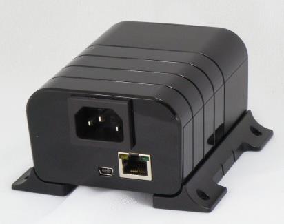
AC Power Connections
Connect the device to be powered ON and OFF to the IEC receptacle marked A/C Output. An IEC 320 to North American (NEMA 5-15) power cord is included for connecting the iBoot-G2 outlet to the device to be controlled.
If a cord with a different terminating receptacle is required, be sure it is properly rated and meets all the required local electrical standards. If the device to be powered uses an IEC320 receptacle and detachable power cord, an IEC to IEC extension cord can be used.
The iBoot-G2 output can be connected to a power strip to allow simultaneous control of multiple devices.
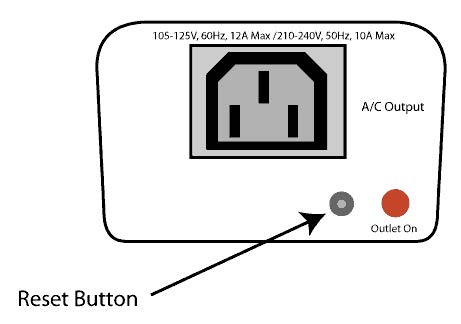
Make sure that the combined load of all controlled devices does not exceed 12 Amps for 105-125VAC or 10 Amps for 210-240VAC.
An LED Indicator next to the Switched Outlet will be On (red) to indicate that the power is On at that outlet. This LED will turn Off to indicate that the power is Off to the outlet.
Connect the supplied power cord to the connector labeled A/C Input, and the other end to your AC source. If a power cord with a different terminating plug is required, be sure it is properly rated and meets all the required local electrical standards.


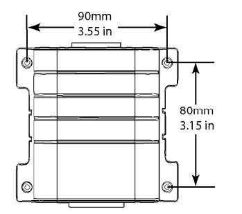
Mounting Options
iBoot-G2 is suitable for desktop or shelf mounting. A mounting kit for wall and DIN rail mounting is available. Order part:
1920034: Mounting Kit for iBoot-G2 G2 Series

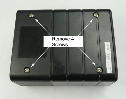
Remove all cables from the unit prior to installing or removing any mounting hardware.
| Installing the Wall Mounting Kit | DIN Rail Mounting | |
| Remove the four mounting screws from the underside of the unit.
|
In stall the Wall Mounting Kit as shown.
|
|
| Do not disassemble the unit.
|
||
| Install the wall mounting ears to the unit using the screws removed in Step 2 | Install the DIN rail clips using the four screws provided.
|
|
| The unit is ready for wall mounting.
|
Ready for DIN rail mounting.
|
|
| Use M3 or #4 screws (not included) for attachment to suitable surface
|
||


Initial Configuration
Auto-Configuration
If your network supports Dynamic Host Configuration Protocol (DHCP), the iBoot will be automatically assigned an IP Address and be ready to use. You can discover the IP Address through your Server/Router, or use Dataprobe’s Device Management Utility (DMU).

DMU Discovers Dataprobe Devices on your Network
Device Management Utility
The DMU provides the easiest means to find and configure your iBoot-G2 for use, and is available online at dataprobe.com/support-iboot-g2/,. It can:
- Discover all the iBoots on your network,
- Display the current IP address of each
- Allow setting of an IP address
- Reset to Factory Defaults
- Upgrade the Firmware of the iBoot-G2

Enter New IP Address for iBoot
Obtain and use the DMU:
- Download the latest version of the DMU at dataprobe.com/support-iboot-g2/
- Run DMUSetup.exe
- Run the DMU

IP Address Successfully Set
Note: The DMU can only set IP address within the first two minutes of powering up the iBoot-G2 or pressing the reset button (see Section 12). The Setup Utility will only work with iBoots on the same physical subnet as the PC.
Once the DMU is run, click on Device | Discover to display all the iBoots on your network. The DMU will display the Location Name of the iBoot, The product ID and Version Number, the current IP Address, and the MAC Address. Factory defaulted iBoots will display with the name iBoot-G2-xxxx where the xxxx are the last 4 segments of the MAC address, and have the factory default IP address of 192.168.1.254, or as set by DHCP.
The IP address field also indicates the port for web access that is used by the iBoot. The standard port for web browser control is factory default Port 80.
Change the IP Address
- Click on the row containing the iBoot-G2 to be set. The row will become highlighted.
- From the menu select Set | Network Settings
- Select the IP Mode DHCP if you want the network to assign parameters
- Select the IP Mode Static if you want to define all network parameters manually.
- Click OK when done.
Once the IP Address is set, other all other operational features of the iBoot-G2 can be set up. Click on Discover again to refresh the display, highlight the desired iBoot-G2 and click on Manage | Launch Browser. See Section 7 to configure the iBoot.
The DMU can also be used to return an iBoot-G2 to its Factory Default condition. This can be used to recover an iBoot-G2 with a lost password. Highlight an iBoot-G2 from the display and select
Set | Factory Defaults. Using the Utility to reset defaults will not change the network settings allowing you to re-access the unit. You can also use Set | Admin Password to reset only the admin password parameter back to default. These reset options must be done within the first two minutes of powering up the iBoot or pressing the reset button.
Other ways to set the IP Address
- Web Browser via the Set-up Page – See Section 7.2
- Command Line Interface See Section 9
Web Browser Operation

Password Protection
iBoot-G2 uses two username/password credential sets, one for power control only (User) and one that also provides access to the setup functions (Admin). This configuration can be changed to require Administrator credentials at all times or allow unsecured User level control. See section 7.8.
Default Credentials:
| Role | Username (fixed) | Password (settable) |
| Administrator | admin | admin<last 3 MAC segments> |
| User | user | user<last 3 MAC segments> |
The passwords are unique and based on the last 3 segments of the MAC address of the unit.
The MAC address can be found on a sticker on the bottom of the unit. Typical 00-0D-AD-xx-xx-xx. Example: If your MAC address is 00-0d-ad-aa-bb-cc then the admin password is adminaabbcc and the user password is useraabbcc.
Open your browser and enter the IP address of iBoot-G2 into the address bar. If you have changed the IP address by any of the methods described or used DHCP, enter that address, otherwise, use the default IP address 192.168.1.254
Enter the username and password when prompted. When the proper username/password is received the Control and Status Page is displayed.
iBoot-G2 uses an inactivity timer for security. This timeout is user selectable from 0 to 99 minutes. Setting to zero disables the timeout feature. When there is no activity for the set time in minutes, the user is automatically logged out and the username and password will need to be entered again for access. This is to prevent accidental lockout by leaving the user logged in.
As the iBoot-G2 allows only one Web user logged in at any time, use caution when disabling the timeout feature, as it is possible to lock out other users by forgetting to logout. Closing the browser will not log the user out and will lock out web access. If you do become locked out, access the iBoot-G2 via Telnet and reboot the unit, or press the reset button (see Section 12).
Mobile Browser Support
iBoot-G2 uses adaptive web pages to accommodate desktops, tablets and smartphones. No additional apps are needed to access the complete features.

Control and Status Page
Once the user is validated, the Control and Status page is displayed. (Only one person can be connected to the iBoot-G2 at a time.).
This page provides automatic updates every 5 seconds.
To control the power, click on the appropriate button. During power cycling, the Power Status bar will indicate the temporary status, with a blue background. Once the cycle is complete, the status bar will revert to its original condition. To abort a power cycle, click on either Power On or Power Off buttons.
If the AutoPing feature is in use, the page will also display the current status, OK or Failed, for each AutoPing in use, with a counter of how many times action was triggered. If connecting with the Admin credentials, reset button for the Trigger counter is provided.

If the iBoot-G2 is connected to a time server (see Section 7.3), The Home page will also show the five most recent history events, including the Outlet, Action, User and Time/Date of each event. The iBoot-G2 holds the last 32 events in memory. The user can access a complete history webpage, download the history in a .csv file, or clear the history.
Navigation Menu:
Refresh: Use the Refresh button to obtain the latest status of iBoot. Using your browser’s refresh button can lead to inadvertent power switching. If an NTP server is being used, the time of the last refresh will be shown in the upper right corner. ( As of: )
Logout: When you are finished with iBoot, click on Logout. A Goodbye page will be displayed. This page has a URL link to re-connect with the iBoot. The linkback URL is user settable. If no linkback is set, the hyperlink will be the unit’s IP Address.

Logout with linkback set for iBoot-G2-bbcc
Setup: To access the Setup page, the administrator credentials are required. When logged in as User, the challenge for Administrator credentials will be displayed.
URL Control
iBoot-G2 can be controlled directly by sending a completely formed URL through a browser window or HTTP command. The URL syntax for control is:
http://<address>?s=<status>&t=<time>&u=<user>&p=<password>
Where:
- <address> = the IP Address of the device, or DNS name that resolves to the IP Address, Including any HTTP Port if not standard 80
- <status> = The status to change the outlet to:
- 0 = Off
- 1 = On
- 2 = Query only, no outlet change
- <time> = The amount of time to cycle
- <user> = user or admin depending on password used
- <password> = password associated with user
Syntax notes:
- The order of the variables is not significant.
- The user and password are not required when Auto-Login feature is enabled (see Section 7.8 for security options.
Examples:
http://192.168.1.254?s=1&u=user&p=useraabbcc (Turn the outlet on for the default user. )
http://192.168.1.254?s=0&t=5 (Reboot for 5 seconds with Auto-Login )
http://192.168.1.254:8080?s=2&u=admin&p=adminaabbcc (Return status using http port 8080)
URL Command Responses
iBoot-G2 will return an response to a URL command as follows: <location id> <status>
The full http response is
<!DOCTYPE html PUBLIC “-//W3C//DTD XHTML 1.0 Transitional//EN”
“http://www.w3.org/TR/xhtml1/DTD/xhtml1-transitional.dtd“>
<html xmlns=”http://www.w3.org/1999/xhtml“>
<head>
<meta http-equiv=”Content-Type” content=”text/html; charset=utf-8″ /> <title>iBoot Status</title>
</head>
<body>
<locationID>iBoot-G2</locationID>
<status>OFF</status>
</body>
</html>
Web Setup
iBoot-G2 setup section consists of several pages. Access any page via the buttons on the left of the page. Each time a setting is changed click on the Save button for that page to save the changes before moving to the next page.
Device Settings
- Location ID: Set a 20 Character name to be displayed on the top of the Home page. This assists in identifying which iBoot-G2 is being accessed. The Location ID is used with LLMNR and a reboot will be required to apply the new name See section 7.10 to learn more about LLMNR.
- Cycle Time: 1 to 999 seconds power cycle time. This is the length of time the power will be off during a reboot, or on during a power burst.
- Disable Off: When checked, this will not allow the iBoot-G2 to turn Off. Cycle will cause a reboot, but not command will leave the power in the OFF state.

Unchecked the unit will function normally and allow an off outlet. (See section 7.9)
- Initial State: The outlet can be set to the state it will assume when the iBoot-G2 is powered up or reset. The choices are: On, Off and Last, meaning the state it was in when the power was removed or reset commenced.
- Upgrade Enable: Check this box to allow remote firmware upgrades of the iBoot-G2. When this box is unchecked, firmware upgrades will not be allowed.
- Auto Logout: This setting sets the automatic logout for inactivity on both the web and telnet users. It can be set from 0 to 99 minutes. 0 disables the Auto Logout feature.
As the iBoot-G2 allows only one Web user logged in at any time, use caution when disabling the timeout feature, as it is possible to lock out other users by forgetting to logout. Closing the browser will not log the user out and will lock out web access. If you do become locked out, access the iBoot-G2 via Telnet and reboot the unit, or press the reset button.
Network Settings
MAC Address: the Mac address of the unit is displayed for reference.
- IP Mode: Select Static to set the IP address using the fields below, or DHCP to allow a DHCP server to set the IP Address.
- IP address: Enter a static IP address. This will be automatically set if using DHCP
- Subnet Mask: Enter the Subnet Mask. This will be automatically set if using DHCP
- Gateway: Enter the Gateway. This will be automatically set if using DHCP
- DNS: Enter the Domain Name Server address. This will be automatically set if using DHCP.

Advanced Network Settings
HTTP Port: This setting is used to allow access to iBoot-G2 on a port other than the Web standard Port 80. If the port is changed, you will need to identify the port number when you enter iBoot’s IP address into your browser. If the new port is 8080 then use the address http://192.168.1.254:8080.
Linkback URL: This setting allows control of the hotlink displayed on the Goodbye page. It allows use of the public IP address or DNS name instead of the internal IP Address of the iBoot-G2, which is the default setting. If this setting is left blank, the hotlink will be the IP Address of the unit. Enter up to 128 characters.

Telnet Port: This setting is used to allow access to the iBoot-G2 via telnet by ports other than standard 23.
DxP Port: This setting is used to allow access to the iBoot-G2 via Dataprobe Exchange Protocol (DxP) via ports other than standard 9100.
Enable Cloud Services: This setting enables the iBoot for iBoot Cloud Services (iBCS). iBCS allows the iBoot to be monitored and controlled from a web portal from any browser. It allows multiple iBoots to be managed from a single portal. For a complete description of iBCS and setup instructions, see Section 8.
Note: All of the TCP/IP Settings require a reboot of the iBoot-G2, after clicking Save. A Reboot button will appear at the bottom of the page. The new settings will not take effect until the unit is rebooted. Reboot will not affect the power position of the iBoot-G2. Upon Clicking Reboot, the Rebooting page is displayed with a link to re-login.
Time Setup
The Advanced Network Setup page also allows setup of the Time server, required for Scheduling and Logging functions.
- Enable: Enable or Disable the use of the Time Server with this checkbox
- Time Server: Enter the Time Server. The default is time.nist.gov
- Time Zone: Enter the Time Zone (-12 to +12) relative to GMT
- DST Enable: Enable or Disable the use of Daylight Savings Time with this checkbox
- DST Start / Stop: Enter the start and stop parameters of Daylight Savings Time here.
AutoPing
The AutoPing feature allows iBoot-G2 to automatically detect failed equipment and perform a timed reboot or other power control function (like turning on an indicator or siren). You set one or two IP addresses to be periodically pinged. When iBoot-G2 no longer detects a response from these addresses, the programmed power control function is actuated. The two addresses can be AND or OR linked so that both (AND) or either (OR) need to fail in order to take the selected action.
Examples:
Use Auto-Ping as network monitor: iBoot-G2 is installed with the device to be rebooted, but pings a remote host to test the communication channel. Ideal for: DSL & Cable Modem Verification Use
AutoPing as server monitor: iBoot-G2 is installed with the device it monitors and automatically reboots if there is no response. Ideal for: Kiosks & Servers.
AutoPing as an Alert Generator: iBoot-G2 monitors network device and powers up alarm, environmental response or redundant system. Ideal for: Hot Standby Servers, Environmental Control, Alert for any Network Failure.


AutoPing Settings
Address: Enter the IP address of the device, or domain name to be pinged. To enter the second address and settings, select AND or OR for the A/B Logic.
Ping Frequency: Enter 1 to 999 seconds. The ping will go out to the selected device this often.
Fail Count: Enter 1-999 times the ping needs to fail consecutively before the selected action is taken. When the fail count has been reached, the AutoPing action will be triggered.
Mode: Select from Single, AND, OR. With AND, both AutoPings need to exceed their fail count to trigger the Action. With OR, the Action will be triggered if either AutoPing fails.
Action: Select from
| None | AutoPing is paused. No Ping tests will be performed. |
| Power On – Latch | Upon triggering, iBoot-G2 will power on and remain so until changed via the web, telnet, DxP, etc. |
| Power On – Follow | Upon triggering, iBoot-G2 will power on. When the ping response returns, iBoot-G2 will power off. |
| Power Off – Latch | Upon triggering, iBoot-G2 will power off and remain so until changed via the web, telnet, DxP, etc. |
| Power Off – Follow | Upon triggering, iBoot-G2 will power off. When the ping response returns, iBoot-G2 will power on. |
| Cycle Cycle Times |
Upon triggering, iBoot-G2 will cycle the power. If Power Cycle does not result in the ping response the iBoot-G2 can cycle again. The number of times the iBoot-G2 will cycle is set by the Cycle Times setting. To have the iBoot cycle power 3 times to get the system to respond again, set the Cycle Times to 3. |
Restart: This setting delays the restart of the AutoPing tests after the Action is completed. This setting allows time for the boot sequence of the failed device to complete.
With AutoPing operational, the main iBoot-G2 page will display the current status of this feature. The status will be OK to indicate that iBoot-G2 is receiving responses to the ping, or that the fail counter has not yet been exceeded.
If the fail count has been exceeded, the status will change to FAIL. The Trigger Counter indicates the number of times the AutoPing action has been triggered. A counter reset button is provided.
Note: All of the AutoPing Settings require a reboot of the iBoot-G2, after clicking Save. A Reboot button will appear at the top of the page. The new settings will not take effect until the unit is rebooted. Reboot will not affect the power position of the iBoot-G2. Upon Clicking Reboot, the Rebooting page is displayed with a link to re-login.
Event Scheduling
iBoot-G2 can schedule up to eight reoccurring power events. Set the starting date and time, plus the action to be taken and any repeat cycle for each.
To enable the time scheduling function set the network time server in Advanced Network Setup, Section 7.3.
Once the time server is active, scheduled events can occur. Up to eight independent scheduled events can be programmed.
- Date: Set the initial date for the event. The format for the date is mm/dd/yyyy.
- Time: Set the initial time for the event. The format for the time is hh:mm with hours in 24 hour format.
- Repeat: Set the repeat multiplier, if desired. Set the number from 0 to 999 and either Days, Hours, or Minutes. To have the schedule repeat every two days, set this number to 2 and selection to Day(s).

Action: Set the event Action; On, Off or Cycle.
Enable: When this box is checked, the event will occur at the programmed time. When it is unchecked, the event will not occur, but the next calculated event time will be displayed.
Clear: Delete the scheduled event.
Click Save to save the current settings. Click Reset to delete any unwanted changes.
Password Settings

The iBoot-G2 supports three modes of user and password operation.
Login Required: This mode supports both User and Admin users. Each user has a settable password.
Auto Login: This mode does not require a username of password for the User level operation. No login challenge will be required for any mode of operation, until any setup function is requested. The Admin username and password is required for any admin functions.

User Disabled: There is no User account.
The Admin username and password will be required for operation and setup functions across all modes of operation. This is the factory default mode.
Two passwords are used by the iBoot. In the Login Required mode, The User Password allows access to the control of iBoot, but not to the Setup functions. Clicking on the Setup button allows the Administrator to log in. Passwords can be up to 20 characters long and are case sensitive.
Enter the current password then the new password twice to confirm.
Default Credentials
| Role | Username (fixed) | Password (user set) |
| Administrator | admin | *adminxxxxxx |
| User | user | *userxxxxxx |
The passwords are unique and based on the MAC address of the unit. (the xxxxxx are the last 3 segments) The MAC address can be found on a sticker on the bottom of the unit. Typical 00-0D-AD-XX-XX-XX.
Example: If your MAC address is 00-0d-ad-aa-bb-cc then the admin password is adminaabbcc and the user password is useraabbcc.
Disable Off
When Checked, this feature is enabled and insures that the power to the controlled device will always be on whenever possible. No accidental turning or leaving the power off is possible.
To use the “Disable Off” feature
WEB – On the Setup > Device page check the enable box next to the Disable Off: option and Save.
CLI – telnet to the unit and issue the Command Line Interface command.
set disable off yes
Use the following to determine the current status of the feature.
get disable off
The response will be Disable Off: Yes or Disable Off: No
Yes will indicate it is enabled and No will indicate it is disabled. By default, the feature is disabled.
To stop using this feature issue the command
set disable off no
When the feature is enabled, (checkbox is checked) the following will occur:
- If the outlet is Off at the time the feature is enabled, the outlet will turn On
Initial state will be programmed for On - Initial state will not allow programming for Off or Last
- If AutoPing action programmed for On-Follow, Off-Latch or Off-Follow, the autoping action will be reprogrammed as None
- AutoPing action will not allow programming for On-Follow, Off-Latch or Off-Latch
- If a Schedule Settings event has action for Off, it will be reprogrammed for On
- Schedule Settings will not allow programming for action Off
- Web page will not show the “Power OFF” button
- Web Page will not process an HTTP POST for Off.
- URL control will not process an unqualified off status request (s=0) A qualified off status request with a time setting (s=0&t=1) of 1 or more will be processed allowing for URL control to cycle off, then back on
- URL control will not process a qualified on status request with a time setting (s=1&t=1) of 1 or more (disabling URL control to cycle on then off)
- DxP control will not process an Off command
- DxP control will not process a pulse on command. pulse on commands end with outlet off
- DxP control Pulse Off commands, while in progress, will not allow cycle commands to override them.(avoiding potentially having a completed cycle end as off)
- Cycle commands, while in progress, will not allow new cycle commands to override them. (avoiding potentially having a completed cycle end as off)
- Command Line Interface (CLI) control will not process “set outlet off”
- If cloud control is enabled, the Off command will not be processed.
Disabled
When the feature is disabled, (checkbox is unchecked) all the modes that can turn the power off will be available and functioning.
Local Link Multicast Name Resolution (LLMNR)
The Link-Local Multicast Name Resolution (LLMNR) is a protocol based on the Domain Name System (DNS) packet format that allows hosts to perform name resolution on the same local link.
On most networks you will be able to access the iBoot-G2 by its device name when on the local network. By default the name is iBoot-G2-xxxx where the xxxx is the last 4 segments of the MAC address for your iBoot-G2. When you reprogram the name of the device, a reboot is required to apply the new name as the LLMNR for the device.
The LLMNR name does not allow spaces. If using the LLMNR feature to access the iBoot-G2, do not use a space in the name. When accessing the device type the complete URL including the http:// in order to avoid searching the internet for the name. ( http://iBoot-G2-xxxx )
When the Location ID is changed the device will require a reboot to re-register the new name to your networks llmnr server. This means access using https://iBoot-G2-aabb should work, or a renamed myiboot would be accessible as http://myiboot . To make use of llmnr, you must choose a name with no space or special characters. ( dashes are allowed )
iBoot Cloud Service
iBoot Cloud Service (iBCS) allows customers with iBoot to access and control multiple iBoots in multiple locations from a single portal with a single sign-on.

iBCS will not only make using iBoots easier, by consolidating all units into one sign-on and interface; it will also enhance the number of situations where iBoot can be deployed.
- Customers with Dynamic IP addressing will always be able to access their iBoot from any location.
- Customers that do not allow in-bound connections can access their iBoots.
- Service providers can manage multiple customer accounts with diverse security configurations
iBCS Setup & Operation
Use of the iBoot Cloud Services requires the iBoot to be configured to access the Internet. Please review the installation and configuration procedures to insure proper setup.
Establish Account with iBoot Cloud Server
- Visit http://iboot.co from your browser
- Click on Register
- Complete the information
- Confirm Registration by clicking on the link provided in the email.
Enable Cloud Services on iBoot
- Log into the iBoot with Administrator rights
- Go to the Advanced Network Setup page
- Check Enable Cloud Services, and Save:
- Within 30 seconds, an 8 character activation code will appear.
- This code is also a hotlink to the Cloud Service.

Register iBoot with Cloud Account
Click on the Activation code to register the iBoot with the Service.
You will be re-directed to the Service. Log-in with your account and the iBoot will be automatically registered with your account.
Alternatively, you can log in to the Service and click on Add Device and enter the activation code in the field provided.
Congratulations. You are now on the cloud. 
iBCS Main Page ![]()
The iBCS main web page provides an Icon for Account Settings The Accounts Settings Icon. will show:
Notification Settings: Where and When to send offline and online stats changes
Account Settings: Account Login Information including Multiuser Mode and LDAP settings Logout: Log out of the Interface
The iBCS will also provide a Navigation Bar and it will show the following:
Search: Search for Devices or Locations

View: Locations, History or Support
Locations: Group iBoots by location.

History: Shows a history of account access.
Support: Will open a new tab to the support pages
Add: Device and Location names can be added
Device: Enter the Activation Code
Location: Create a new cloud location
Expand All: All locations visible will be expanded
Collapse All: All locations visible will be collapsed # or None selected: number of outlets selected
Clear All: De-Select all outlets
Control Power from the Cloud
The status screen will detail available iBoots registered with the cloud. You can add locations and group iBoots by location.
Each iBoot displays its power status and when expanded, the AutoPing status if configured.
Select and outlet and then the On, Off or Cycle button that will appear in the Navigation bar.

Assign Names and Locations
You can establish multiple locations and assign multiple iBoots to a location.
To add locations, click Add Locations from the Navigation bar. Name the location and Add Location button.
To rename or relocate an iBoot, Click the Edit icon for the iBoot.
Use Website for more help
Navigate to this page for helpful videos and other guides. https://dataprobe.com/iboot-cloud-service/
Command Line Interface
The iBoot-G2 Command Line Interface (CLI) provides a text based method for communicating with the iBoot. The syntax of the CLI uses a basic Set (change a variable) and Get (retrieve a variable). The CLI is accessed either through the Telnet protocol, which requires a Telnet client program. Dataprobe provides a simple Telnet Client program (EZ Term) at http://dataprobe.com/support-iboot-g2.
CLI Access
Open the Telnet client and connect to the IP address set for the iBoot.
The CLI uses the same security options as the web browser. See section 7.8 for an explanation of the options for user setup and security.
When connection is successful, the User> prompt is displayed. Enter user or admin and press Enter. The prompt will change to Password>. Enter the admin or user password and press Enter. The prompt will change to iBoot>. This indicates successful login. Enter commands as needed. When done, enter the logout command.
Note: The telnet session will auto-disconnect if there is no activity. The maximum auto-disconnect time is 8 minutes. If the Auto-Logout setting is shorter than 8 minutes, that setting will apply. To avoid this and use a longer auto-disconnect time, use a telnet client that periodically sends a No Operation (NOP) command, like Dtelnet.
iBoot-G2 CLI Syntax
| Command | Description | Factory Default |
|
Control Commands |
These commands are used to monitor and control the outlet. |
|
| set outlet <on | off | cycle> | This command controls the outlet. | |
| get outlet | This command returns the current status of the outlet. | |
|
Device Commands |
These commands are available to the administrator only |
|
| get location | This command returns the iBoot-G2’s location ID. | iBoot-G2 |
| set location <20 char. max> | This command is used to set the iBoot-G2’s location ID. | |
| set cycle <1-999> | This command is used to set the cycle time, in seconds | 10 |
| get cycle | This command returns the current cycle time | |
| set upgrade enable <yes | no> | Enables or disables the ability to upload new firmware to the iBoot-G2. | No |
| get upgrade enable | This command displays the upload enable status. | |
| set disable off <yes/no> | When enabled with yes the feature is active. When disabled with no the unit is as any other iBoot-G2. see section 7.9 | No |
| get disable off | This command displays the disable off status | |
| get initial state | Displays initial state for outlet (On, Off, Last) | |
| set initial state <on | off | last> | This command sets the initial outlet state when power is restored to the input of the iBoot, or after a reboot. | Last |
| login | Prompts for admin credentials when logged in as user | |
| logout | Terminates the session | |
| reboot | This command reboots the iBoot-G2. | |
|
Network Commands |
All set commands require a reboot before they take effect. These commands are only available to the administrator. | |
| Get network | This command will return all the network settings as shown below: Mode: DHCP IP Address: 192.168.1.254 Subnet: 255.255.255.0 Gateway: 192.168.1.1 DNS: 8.8.8.8 HTTP Port: 80 Linkback URL: Telnet Port: 23 DxP Port: 9100 Timeout: 20 |
|
| set ipmode <static | dhcp> | This command sets the ip address setting mode. Static mode locks the address as set, dhcp mode allows DHCP server to assign address. | DHCP |
| set ipaddress <dotted decimal> | This command is used to set the iBoot-G2’s ip address. | 192.168.1.254 |
| set subnet <dotted decimal> | This command is used to set the iBoot-G2’s subnet mask. | 255.255.255.0 |
| set gateway <dotted decimal> | This command is used to set the Gateway | 192.168.1.1 |
| set dns <dotted decimal> | This command is used to set the Domain Name Server | 192.168.1.1 |
| set http port <0-65535> | This command sets the port that the iBoot-G2’s web server listens for incoming connections on. When set to 0 the web server is disabled. | 80 |
| set telnet port <0-65535> | This command sets the port that the iBoot-G2’s Telnet server listens for incoming connections on. When set to 0 the Telnet server is disabled | 23 |
| set dxp port <0-65535> | This command sets the port that the iBoot-G2’s DxP protocol service listens for incoming connections on. When set to 0 the Protocol service is disabled.
Note: At least one of the above MUST NOT be 0. The CLI will protect against all 3 from being set to 0. |
9100 |
| set linkback <url> | This command sets the linkback URL displayed on the logout page. | |
| set timeout <0-999> | This command sets the automatic network timeout in minutes 0 = Timeout not used. | 2 |
|
Autoping Commands |
These commands require a reboot before they will take effect. These commands are available to the administrator only. | |
| get autoping | This command returns all of the AutoPing settings as shown below. AutoPing 1 AutoPing 2 Address: 192.168.233.254 iboot.co Frequency: 10 10 Fail Count: 3 3 Status: OK OK Trig Count: 0 0 Mode: Single Action: Cycle Once Wait: 2 Restart: 0 |
|
| set autoping <1 | 2> address <dotted decimal or name> | This command is used to set the address of AutoPing 1 or AutoPing 2. Use IP Address or domain name. | |
| set autoping <1 | 2> frequency
<1-999> |
This command is used to set the frequency (how often the iBoot-G2 sends the ping) for each of the AutoPings. | 10 |
| set autoping <1 | 2> failcount
<1-999> |
This command is used to set the number of consecutive failures the AutoPings must detect before the AutoPing considers the pinged device to be failed. | 3 |
| set autoping mode <single | and | or> | Sets single AutoPing or two AutoPing relationship And or Or. | Single |
| set autoping action <none | on- latch | on-follow | off-latch | off- follow | cycle> | This command is used to set the action that the iBoot-G2 will perform when the autoping triggers. | None |
| set autoping cycle <0-999> | This command sets the maximum number of power cycles when the AutoPing triggers. 0 = Unlimited | 1 |
| set autoping wait <1-999> | This command sets the time, in seconds for the device to respond to a ping. | 2 |
| set autoping restart <1-999> | After an autoping has been triggered, this command sets the time, in seconds before the autoping will resume. (added delay after cycle complete) | 0 |
| User Commands | These commands are only available to the administrator. | |
| get user account | Displays status of user account use parameter. If No only the administrator account is active | |
| set user account <yes | no> | This command sets whether or not a user account is used. If <n> only the administrator account is active |
No |
| get login required | Displays status of login required parameter. If No then power control can occur without the user password. | |
| set login required <yes | no> | This command sets whether or not a login is required for user level operation. A login is always required for admin functions. | Yes |
| set password <user | admin>
<old> <new> <repeat> |
This command is used to set the password of either the user or administrator. | userxxxxxx adminxxxxxx |
|
Event Commands |
These commands are only available to the administrator. | |
| get events | This command displays all scheduled events as shown below. Example: Date Time Repeats Action
|
|
| set time enable <yes | no> | This command enables or disables the use of the time server and scheduled events.
Note: When Adding new events through the CLI. Set this to no to prevent unintended power switching |
No |
| set time server <domain | dotted decimal> | This command is used to set the Address of an available network time server. | time.nist.gov |
| get time | Displays the current time and time server settings: Current Time: 07/30/2015 10:41:05 Timezone: -5 DST: Enabled Starts the 2nd Sunday of March at 2:00 Stops the 1st Sunday of November at 2:00 Server: time.nist.gov |
|
| set event <1-8> <run | hold> | This command is used to all the event to run, or put the event on hold | run |
| set event <1-8> date <mm/dd/yyyy> |
This command is used to set the scheduled action’s start date. | |
| set event <1-8> time <hh:mm> | This command is used to set the time the scheduled action will occur in 24 hour format. | |
| set event <1-8> action <on | off | cycle> | This command is used to set the scheduled action. | |
| set event <1-8> repeat <day | hour | minute> | This command is used to set how often the scheduled action will repeat. | |
| set event <1-8> mult <0-999> | This command sets how often the event will repeat, the number of increments (as set by the command above) before the next event. | |
| del event <1-8> | This command deletes the specified event | |
| Prompts | The CLI will use the following prompts: | |
| User> | This prompts the user to enter his user name (user or admin). This is the first prompt that the user is presented with. | |
| Password> | This prompts the user to enter his password. | |
| iBoot > | This is the prompt that will be displayed after the user has successfully logged in. | |
| iBoot Reboot Required> | This is the prompt that will be displayed whenever there have been changes made that require a reboot. This prompt will remain the active prompt until the iBoot-G2 is rebooted. | |
DxP Protocol
iBoot-G2 supports the Dataprobe Exchange Protocol (DxP) for inter device communications and to allow software developers to integrate Dataprobe product into custom applications. Through the DxP protocol, the developer can:
- Turn on and off power to the Outlet
- Pulse the Power On or Off for a specified about of time.
- Read the status of the Outlet
The DxP Protocol, as well as example code and scripts in a variety of languages are available at http://dataprobe.com/support-iboot-g2/
Firmware Upgrades
The iBoot-G2 can be field upgraded. http://dataprobe.com/support-iboot-g2/
Find the latest version or special purpose versions at
POWER TO THE OUTPUT WILL GO OFF DURING THE UPGRADE
Upgrading the firmware with a minor upgrade (i.e. 1.01.xx to 1.01.yy) will not alter the user defined settings. Major upgrades may or may not reset the iBoot-G2 to factory defaults. Check the release notes for the upgrade before making changes to you iBoot-G2.
- Insure that the Upgrade Enable checkbox is checked in the Network Setup web page of the iBoot-G2
- Run the Device Management Utility, available at the link above. If the iBoot-G2 you would like to upgrade is not visible in the list box, either Select Device | Discover from the menu to locate iBoot-G2 units on the local network, or Select Device | Add from the menu to add the IP address of the iBoot-G2. Once the device is displayed in the list, highlight it
- Select Manage | Upgrade Firmware Enter User Name admin and the Password for the Administrator. Enter the filename of the firmware, or click Browse and find the file of the firmware file to be used. iBoot-G2 firmware uses the extension .g2u If you don’t see any files of that type, make sure the ‘Files of type’ box is set for iBoot-G2 or All Files. Click OK when all the details are entered.
- The upload will begin, and a progress bar will be displayed.
- When the firmware upload is completed, the iBoot-G2 will automatically reset and be ready for use.

Troubleshooting
The iBoot-G2 has a recessed pushbutton switch in the event the unit is not performing as expected. Use the pushbutton as follows:
| Action | Result |
| Momentary (tap) | Soft Reset. Will not change outlet status. |
| 10 Seconds push | Reset to Factory Defaults. Hold the button in until the Outlet LED is blinking, then release. |
| Hold in while and Power up the iBoot | Recovery Mode. Allows upload of new firmware to the current IP Address. Will recover to the Factory default IP Address 192.168.1.254 if the database has been corrupted. |
Factory reset – excluding basic network settings – can be done using the Device Management Utility (DMU) See Section 5.2.
Specifications
Physical
| Height | 2.0” 60mm |
| Width | 3.2” 82mm |
| Depth | 4.2” 107mm |
| Weight | 8.6 oz 244g |
| MTBF | 360,000 hours |
| Temperature | 0 – 50 degrees C |
AC
| Input | IEC 320 C14 |
| Input Cord | 16AWGX3C 10A 250 UL/CSA/VDE Rated (1.25mm2X3C) |
| Voltage Range | Auto Sensing 105-240 VAC |
| Switched Receptacle | IEC 320 C13 |
| Capacity | 12 A Max at 105-125 VAC, 10 A Max at 210-240 VAC |
Compliance
| UL/cUL | UL60950 Listed I.T.E File No. E225914 |
| CE | Directives 89/336/EEC, 92/31/EEC and 93/68/EEC EN 60950: 3rd Edition EN 55022: 1998 Class B |
| FCC | Part 15 Class B |
|
|
|

Network
| Dual 10/100 Unshielded Twisted Pair Ethernet Jacks. |
| IP Addressed, DHCP assigned or Static |
| Internal HTTP Web Server |
| Forms Processing Browser required |
| Telnet Server |
User Settings
Record your Setup here for reference
| Location: | HTTP Port: | ||
| MAC Address: | Auto-Ping Address: | ||
| IP Address: | Auto-Ping Port: | ||
| Subnet Mask: | Heartbeat Port: | ||
| Gateway: |
Technical Support and Warranty
Seller warrants this product, if used in accordance with all applicable instructions, to be free from original defects in material and workmanship for a period of Three Years from the date of initial purchase. If the product should prove defective within that period, Seller will repair or replace the product, at its sole discretion. Repairs may be made with new or refurbished components and replacements may be new or refurbished at the Sellers sole discretion. Repaired or replaced units shall be warranted for the balance of the original warranty, or 90 days, whichever is greater.
If Purchased from Dataprobe Inc.; Service under this Warranty is obtained by shipping the product (with all charges prepaid) to the address below. Seller will pay return shipping charges within the United States. Call Dataprobe Technical Service to receive a Return Materials Authorization (RMA) Number prior to sending any equipment back for repair. Include all cables, power supplies, accessories and proof of purchase with shipment.
If purchased from an Authorized Dataprobe Reseller; Service under this Warranty is obtained by contacting your Authorized Dataprobe Reseller.
THIS WARRANTY DOES NOT APPLY TO NORMAL WEAR OR TO DAMAGE RESULTING FROM ACCIDENT, MISUSE, ABUSE OR NEGLECT. SELLER MAKES NO EXPRESS WARRANTIES OTHER THAN THE WARRANTY EXPRESSLY SET FORTH HEREIN. EXCEPT TO THE EXTENT PROHIBITED BY LAW, ALL IMPLIED WARRANTIES, INCLUDING ALL WARRANTIES OF MERCHANT ABILITY OR FITNESS FOR ANY PURPOSE ARE LIMITED TO THE WARRANTY PERIOD SET FORTH ABOVE; AND THIS WARRANTY EXPRESSLY EXCLUDES ALL INCIDENTAL AND CONSEQUENTIAL DAMAGES.
Some states do not allow limitations on how long an implied warranty lasts, and some states do not allow the exclusion or limitation of incidental or consequential damages, so the above limitations or exclusions may not apply to you. This warranty gives you specific legal rights, and you may have other rights which vary from jurisdictions to jurisdiction.
WARNING: The individual user should take care to determine prior to use whether this device is suitable, adequate or safe for the use intended. Since individual applications are subject to great variation, the manufacturer makes no representation or warranty as to the suitability of fitness for any specific application.
Dataprobe Inc.
Technical Support: 201-934-5111
support@dataprobe.com
www.dataprobe.com/support.html
Documents / Resources
 |
dataprobe iBoot-G2 Web Enabled Power Switch [pdf] Instruction Manual iBoot-G2, iBoot-G2 Web Enabled Power Switch, Web Enabled Power Switch, Enabled Power Switch, Power Switch, Switch |