Data Signs VMS-S5 Front and Rear Trailers

Specifications
- Product Name: VMS-S5
- Manufacturer: Data Signs Australia Pty Ltd
- Control Method: Manual and Remote
- Power Source: Electric
Separating and Joining the Front and Rear Trailers

OH&S: Wear PPE when working with the SATS.
How to Correctly Separate Trailers.
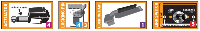
- Undo safety chains that hold the trailers together. Lift up locking bars.
- On Rear Trailer, pull out rear jack stands, rotate all jack stands and lower 25mm from ground.
- Uncouple front trailer from towing vehicle, then lower and use both jockey wheels to level trailers in a straight line with each other. Rear trailer jockey wheel must face inwards.
- Pull out locking pin.
- Use Link switch to engage actuator to push apart.
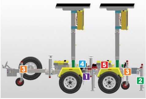
How to Correctly Join Trailers.
- Use jockey wheels (rear wheel facing outwards) to level trailers.
- Insert drawbar on rear trailer into coupling point on front trailer.
- When rear drawbar is below locking pin, place pin back in.
- Push down actuator arm and use.
- Link switch to pull trailers together.
- Ensure safety chains are looped through chassis on left and right, and secured. Adjust locking bars and lock down.
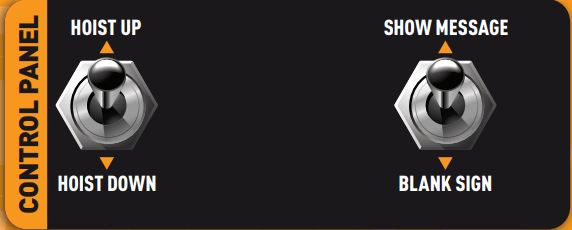
To show message on Sign use the BLANK/SHOW switch located in the control box.
Note: Control panel may look different from what is shown here.
CONTROL PANEL
DS-Live™
Data Signs Subscription Web-based Sign Programming and Active Monitoring.
Data Signs DS-Live™
Data Signs DS-Live™ runs on all web browsers (it is optimized to work best on Google Chrome & Microsoft Edge). It is best suited to run on a PC or Laptop.
It can also work with various popular devices such as iPad, Samsung tablet, etc, however the screen may need to be scrolled to see different items due to the smaller screen size).

.VMS. App
- A portable smart phone App, .VMS. is also available on the App Store or Google Play.
- These web-based applications allow you to update your Sign with new messages, track the location of each Sign, check the battery voltage. Blank and Resume messages etc.
- To subscribe to DS-Live™, get your administrator to do this via the DS-Live™ Platform.

A SIM for Mobile Communications is normally part of the Subscription of DS-Live™, pricing is published from this platform.
Start-up Page
- A Start-up page is displayed when the ST-1 is turned ON, this is done by pressing and holding the lower-right side button.
- Press the
 button to start the Local Connect App.
 - Then select VMS tab
 from the tab at the bottom of the screen.
 - To close the application, tap the
 button in the top-right corner or tap the square box in the bottom-right and swipe the application.
Exiting the app will disconnect from all devices but the devices will continue their last operation.

Connecting to the VMS
To connect to the VMS, see as per below.

- If Auto Connect is enabled in Settings, the ST1 will start scanning immediately.
- If Auto Connect is not enabled, tap the
 button to begin scanning.
 - Tap on the serial no. when it appears in the list. If Auto Connect is enabled, the remote will automatically connect with the last connected device if it is in range.
- If the last connected device is not in range, the remote will continue scanning and will display all the relevant devices in range.
- To stop automatically connecting with the last connected device, go to the Settings section and disable the Auto Connect option or tap the Clear Auto Connect Serial Nos button.
- To stop scanning, tap the
 button.
 - As the Bluetooth connection is established a progress sequence of 5-stars will appear, and the screen will redirect to the relevant remote screen.
- To disconnect from a the SATS, tap the button in the top right corner.
Disconnecting will stop the Bluetooth connection, but the VMS will continue its last operation.

VMS Remote
- VMS Remote is used to monitor and change the message on a VMS board.
- On the remote screen, the current details of the VMS are displayed.
- Green icons indicate all is OK. Amber icons indicate a warning. Red icons indicate an error. Gray icons indicate the feature is either disabled or not running.

- The VMS board can be BLANKED by tapping the
 button and similarly to SHOW the Message, tap the
  button.
 - To change the message on the sign, tap the
 button.
Message Editor
This section is used to create, edit and save a message.
- NEW MSG: will clear and start a new message
- OPEN MSG: will load a list of saved messages and an option to delete the local messages
- SAVE MSG: will save the current message to the local device.
- TEXT EDITOR: will open the text-editor module to setup a textual frame.
- IMAGES LIST: will open the image-list module with a list of 99 pre-defined images.
- ADD FRAME: will add an empty frame either before or after the current frame.
To change the duration of a frame, change the number in seconds. - DELETE FRAME: will delete the current frame
- SEND LOCAL MESSAGE: will upload the message via Bluetooth to the VMS
If you want the message to appear as Amber only, select the “Send As Amber Message” checkbox first.
The arrow buttons can be used to navigate between frames.

Text Editor
- This section facilitates creation of a text message of up to 4 lines. Each line can have a different colour, font size and left or centre alignment.
- A line of text can contain maximum 12 characters.
For optimum visibility, 3 lines of text, 8 characters wide (2nd font from right) is recommended.
When finished, tap the![]() button to save and set the message on the current frame.
button to save and set the message on the current frame.

Image List
This section has a list of 99 pre-defined images to select from. Tap on Select to set the image to the current frame.

For custom images or messages, see Creating Advanced Custom Messages,.
Radar Setup
- Start by tapping the
 button.
 - Either select a saved setup or create a new Setup.
- STEP 1: Select a message to show when NO vehicles are detected.
- STEP 2: Select what happens when a vehicle approaches the sign.
- If you wish to display a Hi & Lo Message then select the appropriate message.
- STEP 3: Set the road Speed Limit and then set the Max and Min limit.
- Enable Data Logging if you wish.
- (Data Logs are retrieved via the DS-Live Platform and can be set to send to an e-mail address.)
- Finally tap
 and then
  to send it to the VMS The setup will be saved on the ST-1 remote.

Creating Advanced Custom Messages
DS-Live Message
DS-Live Message is a new feature allowing messages created in DS-Live to be uploaded to a VMS board via Bluetooth. Internet access is required to use this feature.
- Connect to a VMS via Bluetooth and tap the
 button.
If internet access is required, a prompt will be displayed. To enable internet access, see step 4 on previous page of this manual.
If you do not have access to DS-Live, please see next section to set this up.

- After connecting to the internet, tap the
 button and log into DS-Live entering your regular login details.
 - After login, select the relevant Folder and Message from the list and tap the

- Please wait for the message upload to complete.
Do not move away from the VMS as it will disconnect the Bluetooth connection.

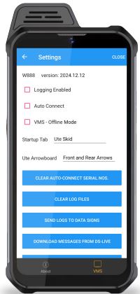
To change the settings, Tap on the Settings Menu button:
- Logging Enabled – enables logging to diagnose issues
- Auto Connect – will automatically connect with the last connected device
- Startup Tab – on startup; the app will jump to this tab directly and will start scanning.
- Clear Auto–Connect Serial Nos – will clear the list of last connected device serial numbers
- Clear Cache – will clear any locally cached data
Removing/Restoring Sign Power
Disconnect the power to the Sign for long-term storage (i.e. longer than a month), for long distance transport, or when working on the Sign. To disconnect the power follow the instructions below.

To restore Sign power, insert the SIGN SUPPLY fuse. Push down to ensure it is properly fitted.
Notes for undercover storage:
Storage outside is recommended so batteries can maintain charge via the solar array. If storing the Sign undercover for a long-term (i.e over one week), unplug the SIGN SUPPLY fuse. Please be aware that the batteries will drain over time; therefore fitting a battery charger is recommended. Battery warranty is voided if batteries allowed to drain below serviceable levels.
To Open Sign Head

LED Board Maintenance

VMS Maintenance
This section details the maintenance procedures. It is important that your SATS are regularly maintained to make certain that your SATS is in continued working order. Note: The Warranty associated with your SATS may be voided if ad-hoc repairs outside the scope of this maintenance section are attempted.
Solar Panels
Keeping the Solar panels clean will ensure they are providing as much energy to charge the battery as possible. To clean the Solar panels, ensure the PTL mast is lowered and that the Jackstands are lowered and extenders fully out.
With a damp and soapy cloth, clean each of the panels, or hose them down (see General Cleaning notes). The solar panels should be cleaned periodically since they can quickly become dusty.
Battery & Circuit Breakers
125AH AGM SEALED BATTERY
CAUTION: LEAD ACID BATTERIES CAN PRODUCE FLAMMABLE GASES WHILE CHARGING. NO NAKED FLAME SHOULD BE ALLOWED NEAR THE PTL’S. TAKE CARE WHEN OPENING AND CLOSING THE BATTERY BOX LID. USE TWO HANDS.
Before attempting any maintenance work on your batteries, make sure the SATS is not in the sun and that it is located in a well ventilated area.

- Remove the fuses.
- Re instate fuses afterward.
- All fuses are normally 25Amp
- Corrosion inhibitor lacquer has been applied to the battery terminals. if replacing battery, use the same after installation to maintain this protection.
- If replacing the battery, use the same rating and type of batteries.
- Notes for Undercover storage: Storage outside is recommended so the battery can maintain charge via the solar array. If storing the trailer undercover for a long-term, unplug the SIGN SUPPLY fuse. Please be aware that the battery will drain over time; therefore fitting a battery charger is recommended.
Trailer Wheels and Wheel Bearings
Regularly check the tyre pressure. At the same time check tyre condition and that the wheel nuts are tight. After a few months of use have a qualified mechanic check. Grease the wheel bearings every 12 months under normal operating conditions. More frequently for adverse/harsh road or operating conditions. Further, check after having travelled 1500 km.
Torque setting for wheel nuts: 65ibs.ft or 90Nm
Tyre Pressure for VMS-S5: 50 psi
Ensure wheel nuts are tightened according to manufacturer specifications for this trailers’ tyre size. If unsure, contact your local mechanic. 13” wheel size, Ford stud pattern.
General Cleaning
The lights and trailer can be hosed. No abrasive solvents or thinners can be used anywhere on the VMS.
Tow Coupling Adjustment
Adjust the tow coupling to fit snugly onto the tow ball of the towing vehicle to improve tow ride. This adjustment is not completed during manufacture as each vehicle tow ball may be a slightly different diameter due to wear or other factors. In Australia, the tow coupling is designed to fit a 50mm ball. Flathead screw driver and shifter required. This is a guide only, please view the disclaimer at the end of the document.
CAUTION: ENSURE THE TOW BALL IS AT THE CORRECT HEIGHT TO THE TOWING VEHICLE, AS INCORRECT AND UNLEVEL TOWING WILL CAUSE DAMAGE TO THE REAR TRAILER COUPLING MECHANISM.

Adjusting the Tow Coupling
- Fit the tow coupling to the vehicle and lock in place. Raise the jockey wheel.
- Release the locking nut.
- Undo the locking nut to give some leeway.
- Using a flat-head screw driver on the slot on top of the pin-bolt, turn until tight, and then loosen very slightly. This will pull the coupling forward onto the tow ball and grip it.
- Check that you can still unhook the coupling without too much effort, but maintaining a tight fit on the tow ball when attached. Use the jockey wheel to assist if required.
- Hold the Pin-bolt with the screwdriver and then tighten the locking nut firmly with a shifter.
Suggestions & Improvements
Data Signs develops its products with the end users in mind. As such, we are always open to suggestions for product improvement. See datasigns.com.au/ServiceSupport/HelpDesk
Disclaimer
The information contained in this document is proprietary information of Data Signs Pty Ltd unless otherwise indicated. Data Signs Pty Ltd make every effort to ensure the quality of the information it makes available. Notwithstanding the foregoing, Data Signs Pty Ltd does not make any warranty as to the information contained herein and does not accept any liability for any injury, loss or damage of any kind incurred by use of or reliance upon the information.
Data Signs Pty Ltd reserves the right to make modifications, additions and deletions to this document at any time and without notice.
The Data Signs logo is a registered trademark of Data Signs Pty Ltd in Australia, New Zealand, United Kingdom, India and United States of America, and a trademark in other countries.
FAQ
How do I subscribe to DS-LiveTM for my VMS-S5?
To subscribe to DS-LiveTM, have your administrator do this via the DS-LiveTM platform. A SIM for Mobile Communications is typically included in the subscription, and pricing information is available on the platform.
How do I start using the VMS-S5 after turning it on?
A start-up page is displayed upon turning on the ST-1. Press and hold the lower-right button to start the Local Connect App. Select the VMS tab to proceed. To close the application, tap the appropriate button in the top-right corner or swipe the application from the bottom-right square box.
Documents / Resources
 |
Data Signs VMS-S5 Front and Rear Trailers [pdf] Instruction Manual VMS-S5 Front and Rear Trailers, VMS-S5, Front and Rear Trailers, Trailers |