Danfoss Termix VVX-I With Complete Insulation
Product Information
Specifications
- Product Name: Termix VVX-I
- Function: Indirect substation for hot water and space heating
- Features: Optimal safety, efficient energy transfer, service-friendly construction, compact design
- Material: Stainless steel and brass components
- Energy Source: Designed for district heating
Functional description
Indirect substation for flats and single family houses.
Application
The Termix VVX-I is a complete solution for hot water and space heating with optimal safety, efficient energy transfer, service-friendly construction and a compact design. The substation is used if a heat exchanger is required or on a conversion to district heating where the existing equipment is unsuitable for direct connection.
District heating (DH)
The substation is prefabricated with a differential pressure controller, fitting piece and sensor pockets for insertion of an energy meter as well as strainers.
Heating (HE)
The heating side consists of a plate heat exchanger, safety valve, manometer, drain valve, air valve, expansion vessel and circulation pump. The temperature of the heating can be controlled thermostatically or by an electronic controller with an outdoor temperature sensor. Depending on the application, different heat exchangers dimensioned for central or floor heating will be used.
Domestic hot water (DHW)
The domestic hot water is prepared in the heat exchanger and the temperature is regulated with a flow-compensated temperature controller with integrated differential pressure controller. The
DH water is cooled very efficiently by the heat exchanger, thereby creating an excellent operating economy. The IHPT valve ensures a stable hot water temperature by varying loads, supply temperatures and by high and varying differential pressure without the need for readjusting the valve. This protects the heat exchanger against overheating and lime scale formation. Furthermore the IHPT valve has an integrated idle temperature controller, which keeps the house supply line warm. This shortens the waiting periods during summer when the heating system is in reduced operation, which is ideal where high comfort is requested.
Safety notes
Safety Notes – general
- The following instructions refer to the standard design of substation. Special versions of substations are available on request.
- This operating manual should be read carefully before installation and start-up of the substation. The manufacturer accepts no liability for damage or faults that result from non-compliance with the operating manual. Please read and follow all the instructions carefully to prevent accidents, injury and damage to property. Assembly, start-up and maintenance work must be performed by qualified and authorized personnel only.
- Please comply with the instructions issued by the system manufacturer or system operator.
Corrosion protection
All pipes and components are made of stainless steel and brass. The maximum chloride compounds of the flow medium should not be higher than 150 mg/l.
The risk of equipment corrosion increases considerably if the recommended level of permissible chloride compounds is exceeded.
Energy source
The substation is designed for district heating as the primary source of energy. However, also other energy sources can be used where the operating conditions allow it and always are comparable to district heating.
Application
The substation is designed to be connected to the house installation in a frost-free room, where the temperature does not exceed 50 °C and the humidity does not exceed 60%. Do not cover or wall up the substation or in any other way block the entrance to the station.
Choice of material
Choice of materials always in compliance with local legislation.
Safety valve(s)
We recommend mounting of safety valve(s), however, always in compliance with local regulations.
Connection
The substation must be equipped with features that ensure that the substation can be separated from all energy sources (also power supply).
Emergency
In case of danger or accidents – fire, leaks or other dangerous circumstances – interrupt all energy sources to the station if possible, and seek expert help.
In case of discoloured or bad-smelling domestic hot water, close all shut-off valves on the substation, inform the operating personnel and call for expert help immediately.
REACH
All Danfoss A/S products fulfill the requirements in REACH.
One of the obligations in REACH is to inform customers about presence of Candidate list substances if any, we hereby inform you about one substance on the candidate list: The product contains brass parts which contains lead (CAS no: 7439-92-1) in a concentration above 0.1% w/w.
Storage
Any storage of the substation which may be necessary prior to installation should be in conditions which are dry and heated.
Authorized personnel only
Assembly, start-up and maintenance work must be performed by qualified and authorized personnel only.
Please observe instructions carefully
To avoid injury to persons and damage to the device, it is absolutely necessary to read and observe these instructions carefully.
Warning of high pressure and temperature
- Be aware of the installation’s permissible system pressure and temperature.
- The maximum temperature of the flow medium in the substation is 120 °C.
- The maximum operating pressure of the substation is 10 bar. PN 16 versions are available on enquiry.
- The risk of persons being injured and equipment damaged increases considerably if the recommended permissible operating parameters are exceeded.
- The substation installation must be equipped with safety valves, however, always in accordance with local regulations.
Warning of hot surface
The substation has got hot surfaces, which can cause skin burns. Please be extremely cautious in close proximity to the substation.
Power failure can result in the motor valves being stuck in open position. The surfaces of the substation can get hot, which can cause skin burns. The ball valves on district heating supply and return should be closed.
Warning of transport damage
Before substation installation, please make sure that the substation has not been damaged during transport.
IMPORTANT – Tightening of connections
Due to vibrations during transport all flange connections, screw joints and electrical clamp and screw connections must be checked and tightened before water is added to the system. After water has been added to the system and the system has been put into operation, re-tighten ALLALLALL connections.
Mounting
Installation must be in compliance with local standards and regulations.
District heating (DH) – In the following sections, DH refers to the heat source which supplies the substations. A variety of energy sources, such as oil, gas or solar power, could be used as the primary supply to Danfoss substations. For the sake of simplicity, DH can be taken to mean the primary supply.
Connections:
- District heating (DH) supply
- District heating (DH) return
- Heating (HE) supply
- Heating (HE) return
- Domestic hot water (DHW)
- Domestic cold water (DCW)
Connection sizes:
- DH + HE: G ¾” (int. thread)
- DCW + DHW: G ¾” (int. thread)
Dimensions (mm):
- With insulation: H 800 x W 530 x D 375
- With cover: H 800 x W 540 x D 430
Weight (approx.): 35 kg
Authorized personnel only
Assembly, start-up and maintenance work must be performed by qualified and authorized personnel only.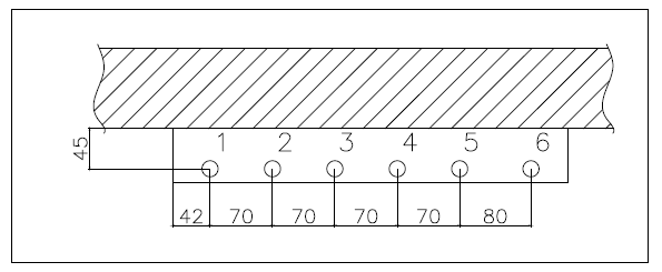
The pipe placement can deviate from the shown drawing. Please note the markings on the station.
Installation
Mounting
- Adequate space
Please allow adequate space around the substation for mounting and maintenance purposes. - Orientation
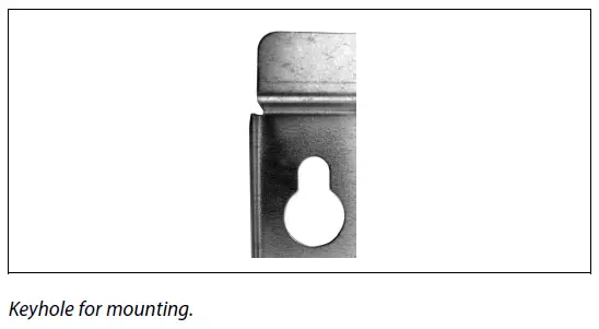
The station must be mounted so that components, keyholes and labels are placed correctly. If you wish to mount the station differently please contact your supplier. - Drillings
Where substations are to be wall-mounted, drillings are provided in the back mounting plate. Floor mounted units have support. - Labelling
Each connection on the substation is labelled.
Before installation:
- Clean and rinse
Prior to installation, all substation pipes and connections should be cleaned and rinsed. - Tightening
Due to vibration during transport, all substation connections must be checked and tightened before installation. - Unused connections
Unused connections and shut-off valves must be sealed with a plug. Should the plugs require removal, this must only be done by an authorized service technician.
Installation:
- Strainer
If a strainer is supplied with the station it must be fitted according to schematic diagram. Please note that the strainer may be supplied loose. - Connections
Internal installation and district heating pipes connections must be made using threaded, flanged or welded connections.
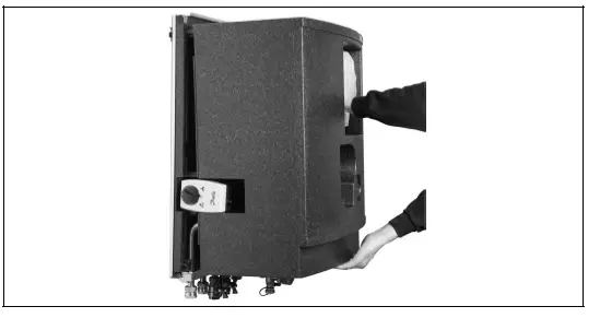
Dismantle the insulation front
Pull the insulation front using the handle in the top of the cover whilst keeping the ECL controller in its place.
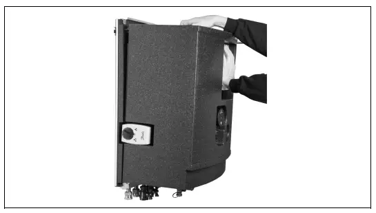
Keep the ECL controller in its position while removing the insulation front completely by pulling at the lower end of the insulation front.
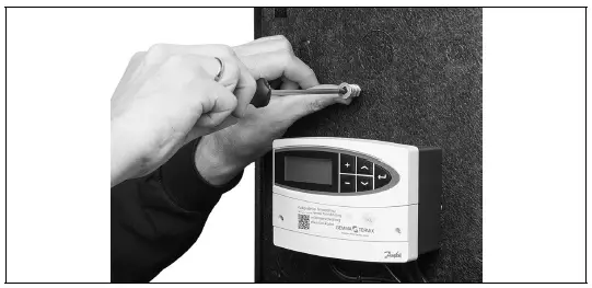
Mounting the display of the energy meter
Mark the position of the fixation points of the bracket for the energy display and screw the two plugs supplied into the insulation front.
Mount the bracket for the display of the energy meter. 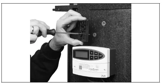
Mount the display/calculator of the energy meter onto the bracket. Pull the wires from the sensors inside the unit through the duct/cut-out in the insulation plate. 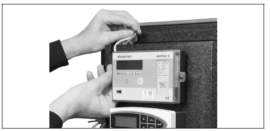
Start-up
Start-up, Indirect heating
Filling:
- First fill
When carrying out first fill, the heat exchanger must be slowly filled with water until it reaches working pressure. - Pressure gauge
The HE pressure gauge indicates the pressure of the HE system. This instruction must be followed strictly, to avoid dangerous situations. - Supply hose
A ball valve with plug is installed in the HE return line. To fill the system, the ball valve must first be closed, the plug removed and a supply hose connected. On re-opening the ball valve, system fill can commence. - Pre-pressure
When filling the system with water, the pressure gauge should be observed closely. The expansion vessel is supplied pre-pressurised to 0.5 bar. The pre-pressure required at each substation will depend on system head (the distance between the lowest and highest point in the system), for example: - Filling stop
Filling must stop when the pressure gauge shows a pressure approximately 1-2 bar higher than the pre-pressure setting. The ball valve is then closed, the hose removed and the plug put back in.
Start-up:
- Pump speed
Set the pump to highest speed before start-up. - Start pump
Start the pump and heat through the system. - Open shut-off valves
The shut-off valves should then be opened and the unit observed as it enters service. Visual checking should confirm temperatures, pressures, acceptable thermal expansion and absence of leakage. If the heat exchanger operates in accordance with design, it can be put to regular use. - Vent system
Switch off the pump and vent the installation after the radiators have been warmed up. - Adjust pump speed
Set the pump to the lowest speed consistent with comfort and electricity consumption.
Normally the change-over switch is set in the mid position (default). However for systems with under floor heating or single pipe loop systems, it may be necessary to turn the change-over switch upwards.
Higher pump speeds are only used if the heating requirement increases.
Re-tighten connections
After water has been added to the system and the system has been put into operation, re-tighten ALLALLALL connections.
Pump
The pump must be switched off during system fill.
| Height (m) | Pressure (bar) |
| 0 – 5 | 0,5 |
| 5 – 10 | 1,0 |
| 10 – 15 | 1,5 |
| 15 – 20 | 2,0 |
Under floor heating:
Pump stop function
If the substation is used in connection with under floor heating, the circulation pump must be connected to the pump stop function in the under floor heating controller. The pump must be stopped if all under floor heating circuits are closed.
Warranty
If this is not possible, then flow must be continued through the by-pass. Failing this, the pump will be at risk of seizure and any remaining warranty will be withdrawn.
Summer operation:
Switch off pump
In summer the circulation pump must be switched off and the shut-off valve to HE supply closed.
Running pump bi-weekly
It is recommended to start up the circulation pump (for 2 minutes) once a month during summer; the shut-off valve of the HE supply must be shut.
Electronic controller
Most electronic controllers will start up the pump automatically (please note manufacturer´s instructions).
Electrical connections
Before making electrical connections, please note the following:
Safety notes
Please read the relevant parts of the safety notes.
230 V
The substation must be connected to 230 V AC and earth.
Potential bonding
Potential bonding should be carried out according to 60364-4-41:2007 and IEC 60364-5-54:2011.
Bonding point on the mounting plate below right corner marked with earth symbol.
Disconnection
The substation must be electrically connected so that it can be disconnected for repairs.
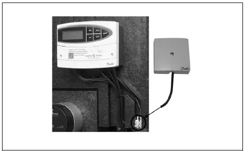
Outdoor temperature sensor
Outdoor sensors should be mounted so as to avoid exposure to direct sunlight. They should not be placed close to doors, windows or ventilation outlets.
The outdoor sensor must be connected to the station on the terminal block under the electronic control.
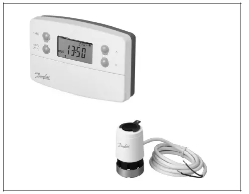
Thermoactuators
Activating the thermoactuators
- The thermoactuators are supplied with a “first open” function, such that they are slightly open for frost protection until the electrical controller is installed. During commissioning, the “first open” function is disabled by removing the red mounting split on the thermoactuator.
- Please check that the thermoactuators can fully close following disablement of the “-first open” function.
- See the installation guide included with the thermoactuator.
Authorized electrician
Electrical connections must be made by an authorized electrician only.
Local standards
Electrical connections must be made in accordance with current regulations and local standards.

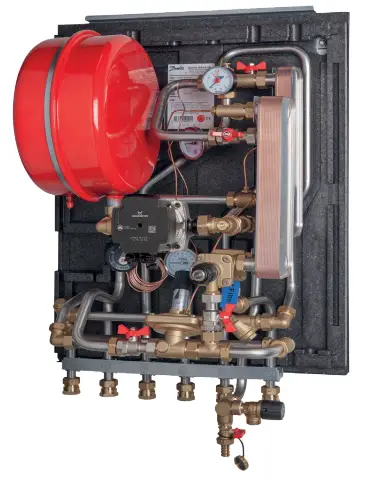
Design
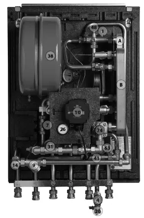
Your substation might look different than the substation shown.
Design description
- A Heat exchanger, HE
- B Heat exchanger, DHW
- 1 Summer valve
- 4 Safety valve
- 7 Thermostatic controller, HE
- 9 Strainer
- 10 Circulator pump
- 14 Sensor pocket, energy meter
- 20 Filling/drain valve
- 26 Pressure gauge, HE
- 31 Differential pressure controller
- 38 Expansion tank
- 41 Fitting piece, energy meter
- 48 Air vent, manual
- 63 Sieve
- 74 IHPT controller, DHW
Schematic diagram
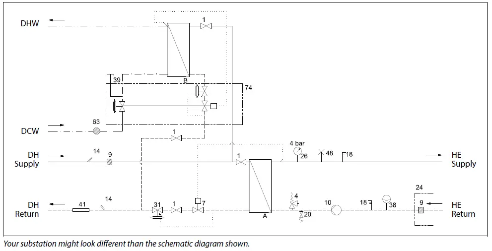
Schematic description
- A Heat exchanger, HE
- B Heat exchanger, DHW
- 1 Ball valve
- 4 Safety valve
- 7 Thermostatic valve 9 Strainer
- 10 Circulator pump
- 14 Sensor pocket, energy meter
- 18 Thermometer
- 20 Filling/drain valve
- 24 Delivered loose with unit
- 26 Pressure gauge
- 31 Differential pressure controller
- 38 Expansion tank
- 39 Connection closed
- 41 Fitting piece, energy meter
- 48 Air vent, manual
- 63 Sieve
- 74 IHPT controller
- DHW: Domestic Hot Water
- DCW: Domestic Cold Water
- DH Supply: District Heating Supply
- DH Return: District Heating Return
- HE Supply: Heating Supply
- HE Return: Heating Return
Technical parameters
- Nominal pressure: PN 10 (PN 16 versions are available on enquiry)
- Max. DH supply temperature: 120 °C
- Min. DCW static pressure: 1.0 bar
- Brazing material (HEX): Copper
- Heat exchangers test pressure: 30 bar
- Sound level: Q 55 dB
Controls
Heating circuit
Differential pressure controller
The differential pressure controller smooths out the fluctuations in pressure arriving from the district heating network. The operating pressure in the substation is thus held steady.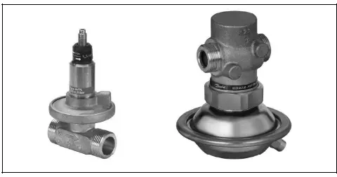
HE temperature control
The HE flow temperature in the heating circuit is controlled by the HE temperature controller.
RAVK controller
RAVK controller (25-65 °C). The temperature setting is as follows:
- 1 = 25 °C
- 2 = 35 °C
- 3 = 45 °C
- 4 = 55 °C
- 5 = 65 °C
The values are intended as a guide.
Thermostatic control
The temperature of the HE flow line is adjusted as follows:
- To increase temperature, turn the handle on the thermostatic controller to select a higher number.
- To decrease temperature, turn the handle on the thermostatic controller to select a lower number.
Electronic control
Substations with electronic control must be set in accordance with manufacturer´s instructions.
Where the room temperature is controlled by radiator thermostats, it is recommended that thermostats be set for minimum temperature in each room.
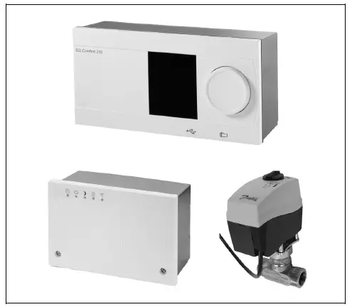 Outside temperature sensor
Outdoor sensors should be mounted so as to avoid exposure to direct sunlight. They should not be placed close to doors, windows or ventilation outlets.
TP7000
TP7000 electronic 7 day programmable room thermostat. Signals from the room thermostat can be used to control zone valves.
Circulator pump UPM3
- UPM3 Pumps can be controlled in constant pressure, proportional pressure or constant speed mode defined by the means of a smart user interface.
- The variable speed modulating modes allow the pump to match its performance to the system requirements, helping to reduce noise when thermostatic valves are closing down.
- Energy labelling class A

Grundfos UPM3 AUTO instructions
Control mode
Each push on the button switches to the next program setting. The choice of operation mode depends on the type of heating system and the pressure loss in the system.

Settings
| Function: | Recommended for: | Green | Green | Yellow | Yellow | Yellow |
| Proportional pressure Auto adapt | ||||||
| Constant pressure Auto adapt | ||||||
| Proportional pressure 1 | ||||||
| Proportional pressure 2 | 2-pipe systems | |||||
| Proportional pressure 3 — MAX | ||||||
| Constant pressure 1 | 1-pipe systems | |||||
| Constant pressure 2 | Under floor heating | |||||
| Constant pressure 3 — MAX | ||||||
| Constant Curve 1 | ||||||
| Constant Curve 2 | ||||||
| Constant Curve 3 — MAX |
Alarm status
| Function: | Recommended for: | Red | Green | Yellow | Yellow | Yellow |
| Power Supply failure | ||||||
| Blocked | ||||||
| Supply voltage low | ||||||
| Electrical error |
HE pressure gauge
The HE pressure gauge indicates the pressure of the HE system.

DHW temperature control
DHW temperature control
There are various types of DHW temperature control used in Danfoss substations.
DHW temperature should be adjusted to 45-50 °C, as this provides optimal utilisation of DH water. At DHW temperatures above 55 °C, the possibility of lime scale deposits increases significantly.
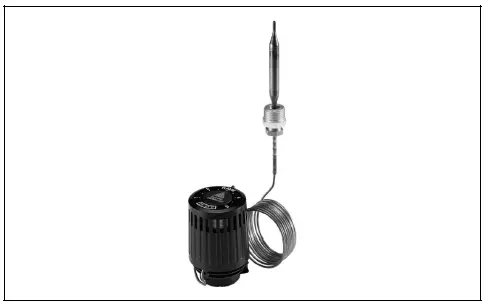
IHPT 90 controller (45–65 °)
- IHPT is a self-acting flow-compensated temperature controller with integrated differential pressure controller.
- The IHPT operates at its best at DH supply temperatures of up to 100 °C.
- By turning the handle for temperature setting in (+) direction the setting is increased, by turning it in (-) direction the setting is decreased.
| Turns* | Scale | DHW Temperature Setting [°C] |
| 0 | 7 | 64 |
| 1 | 6 | 61 |
| 2 | 5 | 58 |
| 3 | 4 | 55 |
| 4 | 3 | 52 |
| 5 | 2 | 48 |
| 6 | 1 | 44 |
| 7 | 0 | 43 |
*Start position: Handle turned fully in (+) direction. The values are intended as a guide.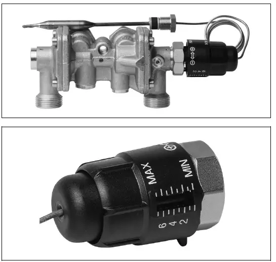
Other
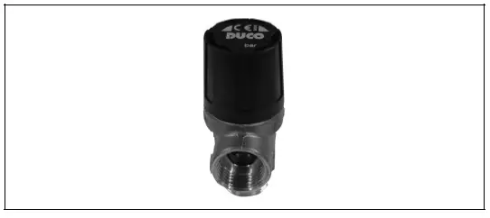
Safety valve
- The purpose of the safety valve is to protect the substation from excessive pressure.
- The blow-off pipe from the safety valve must not be closed. The blow-off pipe outlet should be placed so that it discharges freely and it is possible to observe any dripping from the safety valve.
- It is recommended to check the operation of safety valves at intervals of 6 months. This is done by turning the valve head in direction indicated.
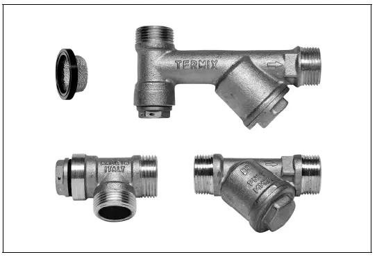
Strainer
Strainers should be cleaned regularly by authorized personnel. The frequency of cleaning would depend on operating conditions and the manufacturer’s instructions.
GTU Pressure Equalizer
- The GTU Pressure Equalizer absorbs the expansion on the secondary side of the Termix water heaters and can be used as a substitute to the safety valve.
- Furthermore the pressure equalizer absorbs a possible increase in pressure, so a discharge outlet is omitted.
- The GTU Pressure Equalizer may not be applied in systems with hot water circulation.

Fitting piece
The substation is equipped with a fitting piece for energy meter.

Assembly of energy meters:
- Close ball valves
Close the ball valves on DH Supply and DH Return, if there is water on the system. - Loosen nuts
Loosen the nuts on the fitting piece. - Remove fitting piece
Remove the fitting piece and replace it with the energy meter. Do not forget the gaskets. - Tighten connections
After mounting of the energy meter remember to check and tighten all threaded connections.
Sensor pocket, energy meter
The sensors of the energy meter is mounted in the sensor pockets.

Extras
Circulation pipe
The circulation pipe set is mounted directly on the controller.
The set includes circulation pipe, single check valve and fitting. When mounting the hot water circulation directly on the controller the hot water circulation temperature will be equal to the idle temperature. The idle temperature is a few degrees lower than the set domestic hot water temperature.

Maintenance
The substation requires little monitoring, apart from routine checks. It is recommended to read the energy meter at regular intervals, and to write down the meter readings.
Regular inspections of the substation according to this Instruction are recommended, which should include:
Strainers
Cleaning of strainers.
Meters
Checking of all operating parameters such as meter readings.
Temperatures
Checking of all temperatures, such as DH supply temperature and DHW temperature.
Connections
Checking all connections for leakages.
Safety valves
The operation of the safety valves should be checked by turning the valve head in the indicated direction.
Venting
- Checking that the system is thoroughly vented.
- Inspections should be carried out minimum every two years.
- Spare parts can be ordered from Danfoss. Please ensure that any enquiry includes the substation serial number.
Authorized personnel only
Assembly, start-up and maintenance work must be performed by qualified and authorized personnel only.
Troubleshooting
Troubleshooting in general
In the event of operating disturbances, the following basic features should be checked before carrying out actual troubleshooting:
- the substation is connected to electricity,
- the strainer on the DH supply pipe is clean,
- the supply temperature of the DH is at the normal level (summer, at least 60 °C – winter, at least 70 °C),
- the differential pressure is equal to or higher than the normal (local) differential pressure in the DH network – if in doubt, ask the DH plant supervisor,
- pressure on the system – check the HE pressure gauge.
Authorized personnel only
Assembly, start-up and maintenance work must be performed by qualified and authorized personnel only.
Troubleshooting DHW
| Problem | Possible cause | Solution |
| Too little or no DHW. | Strainer in supply or return line clogged. | Clean strainer(s). |
| DHW circulation pump out of order or with too low setting. | Check circulation pump. | |
| Defective or clogged non-return valve. | Replace – clean. | |
| No electricity. | Check. | |
| Wrong setting of automatic controls, if any. | To adjust an electronic controller for DHW, pls. note enclosed instructions for electronic controller. | |
| Scaling of the plate heat exchanger. | Replace – rinse out. | |
| Defective motorized valve. | Check (use manual function) – replace. | |
| Defective temperature sensors. | Check – replace. | |
| Defective controller. | Check – replace. | |
| Hot water in some taps but not in all. | DCW is being mixed with the DHW, e.g. in a defective thermostatic mixing valve. | Check – replace. |
| Defective or clogged non-return valve on circulation valve. | Replace – clean. | |
| Tap temperature too high; DHW tap load too high. | Thermostatic valve adjusted to a too high level. | Check – set. |
| Temperature drop during tapping. | Scaling of the plate heat exchanger. | Replace – rinse out. |
| Larger DHW flow than the substation has been designed for. | Reduce DHW flow. | |
| Thermostatic control valve does not close | Temperature difference between DH supply and DHW set point too low. | Lower the set point temperature or increase the DH supply temperature. |
| Idle temperature too low (for stations equipped with IHPT). | Set point too low. | Turn thermostat in (+) direction. |
Troubleshooting HE
| Problem | Possible cause | Solution |
| Too little or no heat. | Strainer clogged in DH or HE circuit (radiator circuit). | Clean gate/strainer(s). |
| The filter in the energy meter on DH circuit clogged. | Clean the filter (after consulting the DH plant operator). | |
| Defective or wrongly adjusted differential pressure controller. | Check the operation of the differential pressure controller – clean the valve seat if required. | |
| Sensor defective – or possibly dirt in the valve housing. | Check the operation of the thermostat – clean the valve seat if required. | |
| Automatic controls, if any, wrongly set or defective – possibly power failure. | Check if the setting of the controller is correct – see separate instructions.
Check the power supply. Temporary setting of motor to “manual” control – see instructions on automatic controls. |
|
| Pump out of operation. | Check if the pump is receiving power and that it turns. Check if there is air trapped in the pump housing – see pump manual. | |
| The pump is set at too low speed of rotation. | Set the pump at higher speed of rotation. | |
| Pressure drop – the pressure drop on the radiator circuit shows lower than recommended operating pressure. | Fill water on the system and check the functioning of the pressure expansion vessel if required. | |
| Air pockets in the system. | Vent the installation thoroughly. | |
| Limiting of the return temperature adjusted too low. | Adjust according to instructions. | |
| Defective radiator valves. | Check – replace. | |
| Uneven heat distribution in building because of incorrectly set balancing valves, or because there are no balancing valves. | Adjust/install balancing valves. | |
| Diameter of pipe to substation too small or branch pipe too long. | Check pipe dimensions. | |
| Uneven heat distribution. | Air pockets in the system. | Vent the installation thoroughly. |
| DH supply temperature too high. | Wrong setting of thermostat or of automatic controls, if any. | Adjust automatic controls, – see instructions for automatic controls. |
| Defective controller. The controller does not react as it should according to the instructions. | Call automatic controls manufacturer or replace the regulator. | |
| Defective sensor on self-acting thermostat. | Replace thermostat – or sensor only. | |
| DH supply temperature too low. | Wrong setting of automatic controls, if any. | Adjust automatic controls – see instructions for automatic controls. |
| Defective controller. The controller does not react as it should according to the instructions. | Call in automatic controls manufacturer or replace controller. | |
| Defective sensor on self-acting thermostat. | Replace thermostat – or sensor only. | |
| Wrong placement/fitting of outdoor temperature sensor. | Adjust location of outdoor temperature sensor. | |
| Strainer clogged. | Clean gate/strainer. |
| Too high DH return temperature. | Too small heating surface/too small radiators compared to the total heating requirement of the building. | Increase total heating surface. |
| Poor utilization of existing heating surface. Defective sensor on self-acting thermostat. | Make sure the heat is distributed evenly across the full heating surface – open all radiators and keep the radiators in the system from heating up at the bottom. It is extremely important to keep the supply temperature to the radiators as low as possible, while maintaining a reasonable level of comfort. | |
| The system is single pipe loop. | The system should feature electronic controls as well as return sensors. | |
| Pump pressure too high. | Adjust pump to a lower level. | |
| Air in system. | Vent the system. | |
| Defective or incorrectly set radiator valve(s). Single pipe loop systems require special one-pipe radiator valves. | Check – set/replace. | |
| Dirt in the motorized valve or in the differential pressure controller. | Check – clean out. | |
| Defective motorized valve, sensor or automatic controller. | Check – replace. | |
| Electronic controller not adjusted correctly. | Adjust according to instructions. | |
| Noise in system. | Pump pressure too high. | Adjust pump to a lower level. |
| Heat load too high. | Defective motorized valve, sensor or electronic controller. | Check – replace. |
Disposal
 Disposal note
This symbol on the product indicates that it may not be disposed of as household waste..
It must be handed over to the applicable take-back scheme for the recycling of electrical and electronic equipment.
- Dispose of the product through channels provided for this purpose.
- Comply with all local and currently applicable laws and regulations.
Declaration
Declaration of conformity


- Gemina Termix A’S
- Member of the Danfoss Group
- danfoss.com
- +45 9714 1444
- mail@termix.dk
Any information, Including, but not limited to information on selection of product, its application or use, product design, weight, dimensions, capacity or any other technical data in product manuals, catalogues descriptions, advertisements, etc. and whether made available in writing, orally, electronically, online or via download, shall be considered informative, and is only binding if and to the extent, explicit reference is made in a quotation or order confirmation. Danfoss cannot accept any responsibility for possible errors in catalogues, brochures, videos a nd other material.
Danfoss reserves the right to alter its products Without notice This also applies to products ordered but not delivered provided that such alterations can be made Without changes to form, fit or function Of the product.
All trademarks in this material are property Of Danfoss A’S or Danfoss group companies. Danfoss and the Danfoss logo are trademarks Of Danfoss A/S. All rights reserved.
FAQ
- Can other energy sources be used with the Termix VVX-I?
- While designed for district heating, other energy sources can be used if they meet operating conditions and local legislation requirements.
- How should I control the heating temperature?
- The heating temperature can be controlled thermostatically or by using an electronic controller with an outdoor temperature sensor.
Documents / Resources
 |
Danfoss Termix VVX-I With Complete Insulation [pdf] User Guide AQ082486478026en-010501, Termix VVX-I With Complete Insulation, With Complete Insulation, Complete Insulation |


