Danfoss OPTBE Board Functional Extensions User Manual
ENDAT/ SSI , SI N- COS OPTI ON BOARD OPTBE
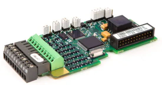
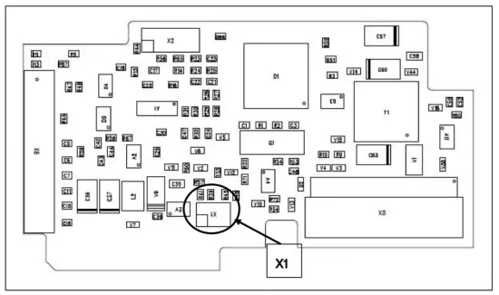
OPTBE l ayo u t a n d d esc r i pt i o n
Description: Encoder board for VACON® NXP with an input for EnDat/SSI absolute encoder and Sin/Cos type encoder.
Allowed slots: C, D, E (Sin/Cos signals can only be used in slot C)
Type ID: 16965
Terminals: One terminal block; Screw terminals (M2.6); No coding.
Jumpers: X1 and X2 (see page 5)
Board parameters: Yes (see page 7)
An absolute encoder is a type of encoder capable of specifying its absolute position. The position data is retained even during a power failure or breakdown. The position data carried by the absolute encoder can be used by the AC drive in motor control and position control applications.
Sin/ Cos encoder produces a pair of analog sinusoidal signals. There are several sine cycles (for example 1024 or 2048) per mechanical revolution.
| Encoder cable | Heidenhain cable Max. length 100m
It is recommended to use a cable which contains individual shield for each twisted pair. |
| Encoder voltage | 5V, 12V or 15V
Max. current consumption 300mA |
| Measuring steps/ revolution | 4.2 billion (max. 32bit) |
| Distinguishable revolutions | 0 65535 (max. 16bit) |
| Sin/Cos signal periods/revolution | 1 65535 |
| EnDat and SSI data transfer rate | 200 kHz |
EnDat is a bidirectional synchronous serial interface for encoders. For example, the absolute encoder position data can be read and encoder parameters can be set via the EnDat connection. It also forwards the messages related to the encoder functions.
All EnDat connections are available in terminal X6. The board uses EnDat version 2.1.
SSI (Synchronous Serial Interface) is a single directional interface for transmitting absolute position value.
The absolute position value beginning with the Most Significant Bit (MSB first) is transferred on the DATA lines in synchronism with a CLOCK signal transmitted by the control. The SSI standard data word length for single turn absolute encoders is 13 bits, and for multiturn absolute encoders 25 bits.
More information on EnDat/SSI: http://www.heidenhain.com.
OPTBE j u mp er s
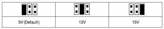
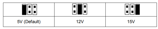
NOTE! It is recommended to use a 12 V or 15 V supply voltage instead of 5 V. OPTBE interface does not support “sense” function to compensate voltage drop with a long cabling. Therefore with 5 V supply voltage the cable length limit is about 60 meters with 0.5 mm2 wire section. With 5 V supply voltage it is recommended to use two or more wires in parallel for the supply connection. Jumper X1 selects encoder supply voltage on the OPTBE board, see jumper settings below:
Jumper X2 selects Sin/Cos signals connection on the OPTBE board, see jumper settings below:
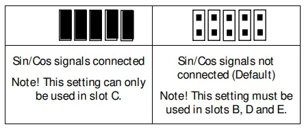
NOTE! Be careful with the jumper settings, wrong settings may damage the encoder.
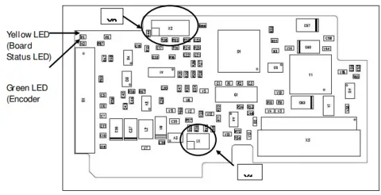
OPTBE LEDs
There are two LEDs on the OPTBE board:
- Yellow LED (Board Status LED)
Slow blinking – > Board state is ready Fast blinking – > Board state is faulted - Green LED (Encoder LED)
ON – > Encoder serial communication is OK OFF – > No serial connection to encoder
1.2 I / O t er mi n a l s o n OPTBE, enc o d er t er mi n a l X6
|
Terminal |
Heidenhain colour code |
Technical data |
|
| 1 | DATA+ | Grey |
Data line 120W/RS-485 |
| 2 | DATA | Pink | |
| 3 | CLOCK+ | Violet | Clock line 120W/RS- 485 (200kHz) |
| 4 | CLOCK | Yellow | |
| 5 | A+, COS+ | Green/black |
1Vpp (±0.5V); impedance 120W; Max. input 350 kHz |
| 6 | A ,COS- | Yellow/black | |
| 7 | B+, SIN+ | Blue/black |
1Vpp (±0.5V); impedance 120W; Max. input 350 kHz |
| 8 | B , SIN- | Red/black | |
| 9 | GND | White/green | Input ground |
|
10 |
Encoder voltage |
Brown/green |
Selectable encoder voltages: 5V, 12V and 15V Max. current consumption 300mA |
Analog Sin/Cos signals deserve some more precautions for noise immunity than pulse encoders. It is recommended to use a cable which contains individual shield for each twisted pair. Use one pair for SIN+/SIN- signals, another pair for COS+/COS- signals, another pair for DATA+/DATA- signals and another pair for CLOCK+/CLOCK- signals.
1.3 OPTBE Pa r amet er s
Notes for selecting Operating Mode:
In modes “EnDat + Sin/Cos” and “SSI+Sin/Cos” Sin/Cos signals and absolute serial information are used:
- Modes can be used in VACON®NXP option board slot
- Closed loop motor control mode can be
- Jumper X2 is installed into OPTBE board because Sin/Cos signals are In modes “Endat Only” and “SSI Only”, only the absolute serial information is used:
- Modes can be used in VACON®NXP option board slots C, D and
- Closed loop motor control mode cannot be Usage of closed loop in these modes causes Fault 43 (Encoder fault) with Subcode 10.
- Jumper X2 is removed from OPTBE board because Sin/Cos signals are not
| Number | Par ameter | Min | Max | Default | Note |
|
7.x.1.1 |
Operating Mode |
4 |
8 |
4 |
4 = EnDat + Sin/Cos (default)
5 = EnDat Only 6 = SSI+Sin/Cos 7 = SSI Only 8 = Sin/Cos Only |
| 7.x.1.2 | Pulse/revolution | 1 | 65535 | 1024 | |
|
7.x.1.3 |
Invert direction |
0 |
1 |
0 |
0 = No
1 = Yes |
|
7.x.1.4 |
Reading rate |
0 |
4 |
1 |
Time used to calculate speed actual value. Note: Use value 1 in Closed Loop mode.
0 = No 1 = 1 ms 2 = 5 ms 3 = 10 ms 4 = 50 ms |
|
7.x.1.5 |
Interpolation |
0 |
1 |
0 |
If activated, the sinusoidal incremental pulses are used to calculate the polar angle in order to optimize the encoder accuracy
0 = No 1 = Yes |
|
7.x.1.6 |
SSI data coding |
0 |
1 |
1 |
0 = Binary
1 = Gray |
| 7.x.1.7 | SSI total bits | 0 | 55 | 13 | |
| 7.x.1.8 | SSI revol bits | 0 | 16 | 0 |
1.4 OPTBE mo n i t o r ed va l u es
| Code | Monitor ed value | Unit | Descr iption |
| 7.x.2.1 | Encoder frequency | Hz | Encoder frequency in Hz |
| 7.x.2.2 | Encoder speed | rpm | Encoder Speed in rpm |
| 7.x.2.3 | Com Counter | Message counter for serial encoder communication 0-65535 | |
|
7.x.2.4 |
Revolution counter |
In case multiturn encoders this monitored value counts the revolutions. 0- 65535 | |
| 7.x.2.5 | Absolute position Hi word | absolute position up from 16 bits to 32bits | |
| 7.x.2.6 | Absolute position Lo word | absolute position up to 16 bits |
SI N- COS OPTI ON BOARD OPTAK
OPTAK l a yo u t a n d d esc r i pt i o n
Description: Encoder board for VACON® NXP with an input for Sin/Cos type encoder.
Programmable control voltage.
Allowed slots: C (Sin/Cos signals can only be used in slot C)
Type ID: 16715
Terminals: One terminal block; Screw terminals (M2.6); No coding.
Jumpers: X1 (see page 10)
Board parameters: Yes (see page 11)
Sin/Cos encoder produces a pair of analog sinusoidal signals. There are several sine cycles (for example 1024 or 2048) per mechanical revolution.
OPTAK j u mper set t i n gs
NOTE! It is recommended to use a 12 V or 15 V supply voltage instead of 5 V. OPTAK interface does not support “sense” function to compensate voltage drop with a long cabling. Therefore with 5 V supply voltage the cable length limit is about 60 meters with 0.5 mm2 wire section. With 5 V supply voltage it is recommended to use two or more wires in parallel for the supply connection.Jumper X1 selects encoder supply voltage on the OPTAK board, see jumper settings below:
NOTE! Be careful with the jumper setting, wrong voltage may damage the encoder.
2 . 3 I / O t er mi n a l s o n OPTAK, enc o d er t er mi n a l X6
| Terminal | Technical data | ||
| 1 | N.C. |
Not Connected |
|
| 2 | N.C. | ||
| 3 | R+ | Max 10Vpp (±5V), Min 1Vpp (±0.5V). Typically signal is ~2.5Vpp (±1.25V): at reference | |
| mark moment positive signal, other time negative signal. | |||
| 4 | R- | Impedance 120Ω | |
| Max input 350 kHz | |||
| Reference mark signal | |||
| 5 | SIN+ |
1Vpp (±0.5V); impedance 120W; Max. input 350 kHz, |
|
| 6 | SIN- | ||
| 7 | COS+ |
1Vpp (±0,5V); impedance 120W; Max. input 350 kHz |
|
| 8 | COS- | ||
| 9 | GND | Input ground | |
|
10 |
Encoder voltage |
Selectable encoder voltages: 5V, 12V and 15V Max. current consumption 300mA | |
NOTE! Analog Sin/Cos signals deserve some more precautions for noise immunity than pulse encoders. It is recommended to use a cable which contains individual shield for each twisted pair. Use one pair for SIN+/SIN- signals, another pair for COS+/COS- signals and another pair for R+/R- signals.
2 . 4 OPTAK p a r a met er s
| Number | Par ameter | Min | Max | Default | Note |
| 7.3.1.1 | Pulse/revolution | 1 | 65535 | 1024 | |
|
7.3.1.2 |
Invert direction |
0 |
1 |
0 |
0 = No
1 = Yes |
|
7.3.1.3 |
Reading rate |
0 |
4 |
1 |
Time used to calculate speed actual value. Note: Use value 1 in Closed Loop mode.
0 = No 1 = 1 ms 2 = 5 ms 3 = 10 ms 4 = 50 ms |
|
7.3.1.3 |
Interpolation |
0 |
1 |
0 |
If activated, the sinusoidal incremental pulses are used to calculate the polar angle in order to optimize the encoder accuracy
0 = No 1 = Yes |
2 . 5 OPTAK mo n i t o r ed va l u es
| Code | Monitor ed value | Unit | Descr iption |
| 7.3.2.1 | Encoder frequency | Hz | Encoder frequency in Hz |
| 7.3.2.2 | Encoder speed | rpm | Encoder Speed in rpm |
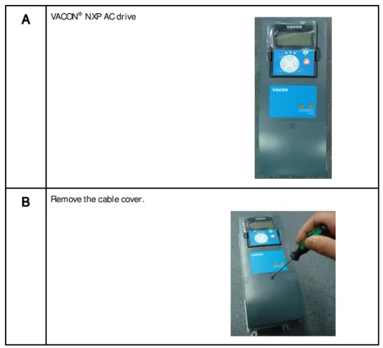
I NSTALLATI ON
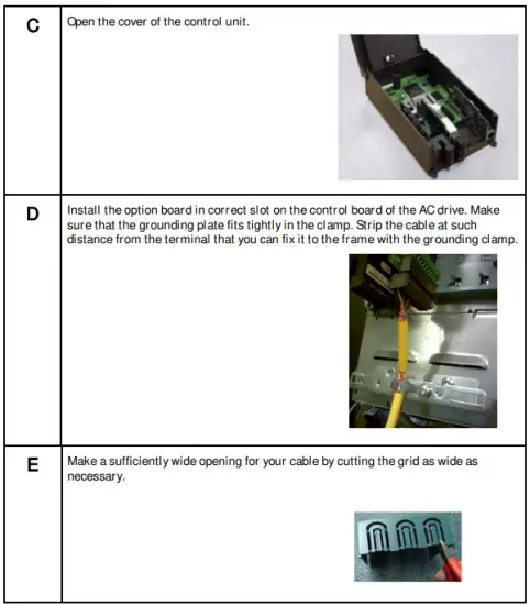
3 . 1 I n st al l i n g op t i on bo a r d s
Option boards OPTBE, OPTAK and OPTAR can only be used with VACON® NXP drives.
OPTAK and OPTAR can be connected to slot C. OPTBE board can be connected to slots C, D or E, but Sin/Cos signals can only be used in slot C. If OPTBE board is connected to slots D or E, the Sin/Cos signals have to be disconnected using the jumpers (see chapter 1.2).
Disconnect the drive from the mains before starting the installation.
Read More About This Manual & Download PDF:
Documents / Resources
 |
Danfoss OPTBE Board Functional Extensions [pdf] User Manual OPTBE Board Functional Extensions, OPTBE Board, Functional Extensions, Extensions |