![]()
Application Guide
Use of DC Connections
iC7-Automation Frequency Converters (1.3–170 A)

Introduction and Safety
1.1 Purpose of the Guide
This application guide describes the different aspects of using DC connections with iC7-Automation frequency converters, including preconditions and typical configurations for DC connection use, and allowed combinations of frames.
![]() IMPORTANT: This guide provides instructions for an IEC-compliant configuration of a DC connection between 2 or more iC7-Automation frequency converters with only 1 drive connected to mains. Using DC connections is allowed only in the configurations described in this guide. For information on other configurations, contact Danfoss.
IMPORTANT: This guide provides instructions for an IEC-compliant configuration of a DC connection between 2 or more iC7-Automation frequency converters with only 1 drive connected to mains. Using DC connections is allowed only in the configurations described in this guide. For information on other configurations, contact Danfoss.
This guide is intended to be used together with the iC7-Automation Frequency Converters Design Guide, iC7 Series Industry Application Guide, and iC7 Series Motion Application Guide.
1.2 Qualified Personnel
To allow trouble-free and safe operation of the unit, only qualified personnel with proven skills are allowed to transport, store, assemble, install, program, commission, maintain, and decommission this equipment.
Persons with proven skills:
- Are qualified electrical engineers or persons who have received training from qualified electrical engineers and are suitably experienced to operate devices, systems, plants, and machinery in accordance with pertinent laws and regulations.
- Are familiar with the basic regulations concerning health and safety/accident prevention.
- Have read and understood the safety guidelines given in all guides provided with the unit, especially the instructions given in the operating guide of the drive.
- Have good knowledge of the generic and specialist standards applicable to the specific application.
1.3 Safety Symbols
The following symbols are used in Danfoss documentation.
![]() DANGER
DANGER
Indicates a hazardous situation which, if not avoided, will result in death or serious injury.
![]() WARNING
WARNING
Indicates a hazardous situation which, if not avoided, could result in death or serious injury.
![]() CAUTION
CAUTION
Indicates a hazardous situation which, if not avoided, could result in minor or moderate injury.
NOTICE
Indicates information considered important, but not hazard-related (for example, messages relating to property damage).
The guide also includes ISO warning symbols related to hot surfaces and burn hazard, high voltage and electric shock, and referring to the instructions.
| ISO warning symbol for hot surfaces and burn hazard | |
| ISO warning symbol for high voltage and electric shock | |
| ISO action symbol for referring to the instructions |
1.4 Version History
This guide is regularly reviewed and updated. All suggestions for improvement are welcome.
The original language of this guide is English.
Table 1: Version History
| Version | Remarks |
| AB481922161456, version 0101 | First release. |
Overview
DC connections enable iC7-Automation frequency converters to be supplied by DC voltage or to supply DC voltage while running in regenerative mode. This is typically done to achieve energy savings and reduce the need for external components.
Table 2: Examples of DC Connection Configurations
| Configuration | IEC-compliant |
DC connection between 2 or more iC7-Automation frequency converters with only 1 drive connected to mains.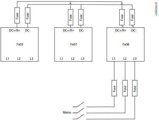 |
See Overview of Application Examples. |
DC connection between 2 or more iC7-Automation frequency converters with more than 1 drive connected to mains. |
Contact Danfoss. |
DC connection between 2 or more iC7-Automation frequency converters and a brake resistor with only 1 drive connected to mains.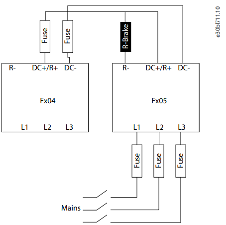 |
Contact Danfoss. |
1 or more iC7-Automation frequency converters supplied only by an active front-end module (AFE), or 1 or more iC7-Automation frequency converters supplied only by DC. |
Contact Danfoss. |
All configurations have common elements, but require different EMC considerations and hardware components, and are therefore treated separately.
![]() CAUTION
CAUTION
- Follow national and local regulations when performing the installation.
- Using a DC connection is only allowed between 2 or more iC7-Automation frequency converters with only 1 drive connected to mains. For other combinations, contact Danfoss.
This guide provides instructions for an IEC-compliant configuration of a DC connection between 2 or more iC7-Automation frequency converters with only 1 drive connected to mains. For information on UL-compliant installations or other configurations, contact Danfoss.
Application Examples
3.1 Overview
In this configuration, only the frequency converter with the highest power rating is connected to mains. The frequency converter connected to mains can supply up to 100% of its own nominal current and use this to charge itself and the frequency converters connected via the DC terminals. The total allowed power of the installation is the nominal power of the frequency converter connected to mains.
![]() IMPORTANT: This configuration example complies with IEC requirements. For information on UL-compliant configurations, contact Danfoss.
IMPORTANT: This configuration example complies with IEC requirements. For information on UL-compliant configurations, contact Danfoss.

NOTICE
ABSENCE OF A BRAKE RESISTOR IN THE CONFIGURATION
- Ensure that the excess energy that is fed back from the drive running in regenerative mode does not exceed the energy of the drive that is running in motoring mode.
![]() IMPORTANT: The frequency converter connected to mains shares capacity with frequency converters connected via DC terminals. As a result, the frequency converter cannot be used at full capacity. For DC-supplied drives, set parameter 2.2.1.5 Supply Mode from to .
IMPORTANT: The frequency converter connected to mains shares capacity with frequency converters connected via DC terminals. As a result, the frequency converter cannot be used at full capacity. For DC-supplied drives, set parameter 2.2.1.5 Supply Mode from to .
![]() NOTE: The power-up time of the application is increased as the frequency converters with lower power ratings supplied from DC terminals are slowly charged through the frequency converter with the highest power rating that is supplied from mains.
NOTE: The power-up time of the application is increased as the frequency converters with lower power ratings supplied from DC terminals are slowly charged through the frequency converter with the highest power rating that is supplied from mains.
Observe the following requirements:
- The frequency converter with the highest power rating can be of any frame as long as it is the frequency converter with the highest power rating in the DC connection configuration.
- The frequency converter with the highest power rating must be dimensioned to supply the remaining frequency converters. Size the frequency converter with the highest power rating to supply the total motor power (generative and regenerative power summed).
- The maximum number of drives allowed in the application must not be exceeded.
- Line reactors are not required for the frequency converter connected to mains.
- Fuses in the DC link must comply with relevant legislation.
3.2 Preconditions
Ensure that the following preconditions are met before considering DC connection use:
- The frequency converters must be equipped with DC terminals (plus code +ALDC).
- The product series of the frequency converters must be iC7-Automation.
- The frequency converters must have the same voltage rating. For example, 380–500 V drives can only be used together with 380– 500 V drives.
- The frequency converters must be placed as close to each other as possible to allow the wiring between them to be as short as possible (maximum 25 m [82 ft]). The wiring must be star-distributed around the frequency converter with the highest power.
- Maximum 5 frequency converters are allowed in a single DC connection setup.
![]() NOTE: Using DC connections may increase the startup time of the frequency converters.
NOTE: Using DC connections may increase the startup time of the frequency converters.
![]() CAUTION
CAUTION
DRIVE READY SIGNAL MONITORING
- All drives must be in Ready state before any drive can run.
- Continuously monitor the Drive ready signal of the frequency converters. The Drive ready signal impacts the overall application control.
- Use parameter 5.26.1.1 Ready Output or the fieldbus status word to monitor the state of each drive. For more information about the status word, refer to the application guide of the application software in use, or to the operating guide of the fieldbus protocol in use.
![]() CAUTION
CAUTION
MISSING PHASE DETECTION AND OVERCURRENT PROTECTION OF THE MAINS SUPPLY REQUIRED
The rectifier in the frequency converter may be overloaded even though the DC link does not show a high level of voltage ripple.
- Equip the mains supply with missing phase detection and overcurrent protection to prevent drive overload.
- Set parameter 1.3.2 Missing Grid Phase Response to Fault.
3.3 Frame Combinations
NOTICE
RISK OF DRIVE FAILURE
Combining frames that are not suitable to be combined may lead to drive failure.
- Ensure that the frame combinations are compatible before combining drives in an application using DC connections.
Table 3: Allowed Frame Combinations in Load Sharing Applications
| DC connection allowed? | Fx02–Fx03 DC connection | Fx04–Fx05 DC connection | Fx06–Fx08 DC connection |
| Fx02–Fx03 on mains | Yes | No | No |
| Fx04–Fx05 on mains | Yes | Yes | No |
| Fx06–Fx08 on mains | Yes | Yes | Yes |
3.4 Configuration Examples
3.4.1 Decanter Centrifuge
In a decanter centrifuge application, the drive for the bowl motor is connected to mains while the drive for the screw or scroll motor is only connected to DC. In this setup, the bowl drive typically runs in motoring mode, and the screw drive or scroll drive runs in
regenerative mode. The screw or scroll drive feeds back the excess energy to the bowl drive to optimize the overall power consumption of the application.

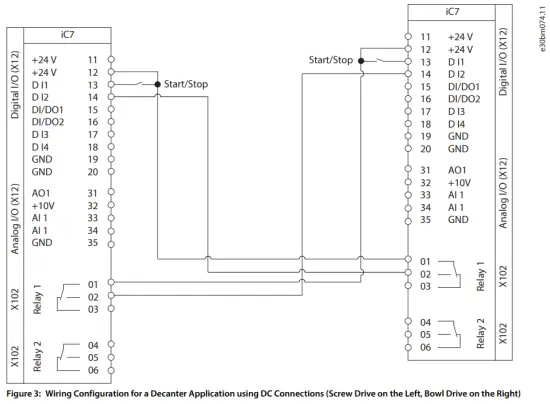
Table 4: Example of Parameter Settings for a Decanter Centrifuge Application
| Parameter | Setting | |
| Screw | Bowl | |
| 1.3.2 Missing Grid Phase Response | Fault | Fault |
| 2.2.1.1 Unit Voltage Class | Set according to voltage class. |
|
| 2.2.1.5 Supply Mode | Set to DC. | Set to AC. |
| 5.26.1.1 Ready Output | Set to Basic I/O Relay T2. | Set to Basic I/O Relay T2. |
| 5.5.2.1 Control Place Selection | Set to Advanced control. | Set to Advanced control. |
| 5.5.6.1.1 Advanced Start Input | Set to Basic I/O T14 Digital Input, Basic I/O T13 Digi- tal Input. | Set to Basic I/O T14 Digital Input, Basic I/O T13 Digi- tal Input. |
| 5.5.6.1.2 Advanced Start Logic | Set to AND. | Set to AND. |
3.4.2 Ring Frame Machine
Ring frame machines typically include a main drive and at least 1 feed roller and 1 TFlex roller, with larger setups incorporating more drives. To avoid costly yarn cuts caused by unsynchronized drive operation in environments with potentially unreliable power grids, it is typical that only the main drive is AC-supplied and provides DC to remaining drives. This approach ensures synchronized operation and mitigates the risk of yarn breaks.
Ring frame machine with 3 frequency converters

- TFlex roller
- Feed roller
- Main drive
In this example, the drives are controlled by a PLC over PROFINET RT. The PLC allows starting only when all drives are ready for operation.
![]() IMPORTANT: Make sure that the PLC does not send a start command before all drives are ready for operation and bit 1 in the status word is set to for all drives, regardless of which fieldbus profile is in use.
IMPORTANT: Make sure that the PLC does not send a start command before all drives are ready for operation and bit 1 in the status word is set to for all drives, regardless of which fieldbus profile is in use.
PLC-controlled setups are more practical in applications involving multiple drives. In this example, fieldbus control can be scaled up for more complex ring frame machines.
Table 5: Example of Parameter Settings for a Ring Frame Machine Application
| Parameter | Setting | ||
| TFlex roller | Feed roller | Main drive | |
| 1.3.2 Missing Grid Phase Response | Fault(1) | Fault(1) | Fault |
| 2.2.1.1 Unit Voltage Class | Set according to voltage class. |
||
| 2.2.1.5 Supply Mode | Set to DC. | Set to DC. | Set to AC. |
1) The default setting does not affect the DC supply mode.
Ring frame machine with 5 frequency converters
In this example, the ring frame machine application is more complex.

- Additional drive
- Additional drive
- TFlex roller
- Feed roller
- Main drive
Table 6: Example of Parameter Settings for a Ring Frame Machine Application
| Parameter | Setting | ||||
| Additional drive | Additional drive | TFlex roller | Feed roller | Main drive | |
| 1.3.2 Missing Grid Phase Response | Fault(1) | Fault(1) | Fault(1) | Fault(1) | Fault |
| 2.2.1.1 Unit Voltage Class | Set according to voltage class.
|
||||
| 2.2.1.5 Supply Mode | Set to DC. | Set to DC. | Set to DC. | Set to DC. | Set to AC. |
1) The default setting does not affect the DC supply mode.
Specifications
4.1 Cables and Fuses
For mains cables, follow the cable requirements stated in the product-specific installation and design guides.
Observe the following guidelines for the DC connection:
- Use the same cable dimensions as for the individual mains connection in normal frequency converter installation conditions without DC connection.
- Always use shielded cables.
- AC fuses must follow the recommended fuse size and type for the drive. See the product-specific design and installation guides for the AC fuse specifications.
- DC fuse requirements can be found in Table 7.
Table 7: DC Fuses for DC Connection Use
| Product code | Frame | Power [kW] | Recomme nded DC fuse size [A] | Fuse voltage [V DC] | Siba fuse part number | Siba type | Fuse class |
| 05-01A3 | FA02 | 0.37 | 3.15 | 1000 | 90 080 10.3.15 | URZ | aR |
| 05-01A8 | FA02 | 0.55 | 3.15 | 1000 | 90 080 10.3.15 | URZ | aR |
| 05-02A4 | FA02 | 0.75 | 3.15 | 1000 | 90 080 10.3.15 | URZ | aR |
| 05-03A0 | FA02 | 1.1 | 6 | 1000 | 90 080 10.6 | URZ | gR |
| 05-04A0 | FA02 | 1.5 | 6 | 1000 | 90 080 10.6 | URZ | gR |
| 05-05A6 | FA02 | 2.2 | 10 | 1000 | 90 080 10.10 | URZ | gR |
| 05-07A2 | FA02 | 3 | 12 | 1000 | 90 080 10.12 | URZ | gR |
| 05-09A2 | FA02 | 4 | 16 | 1000 | 90 080 10.16 | URZ | gR |
| 05-12A5 | FA02 | 5.5 | 20 | 1000 | 90 080 10.25 | URZ | gR |
| 05-16A0 | FA03 | 7.5 | 25 | 1000 | 90 080 10.32 | URZ | gR |
| 05-24A0 | FA04 | 11 | 32 | 1000 | 90 080 10.40 | URZ | gR |
| 05-31A0 | FA04 | 15 | 50 | 1000 | 90 080 10.50 | URZ | gR |
| 05-38A0 | FA05 | 18.5 | 63 | 1000 | 90 080 10.63 | URZ | gR |
| 05-43A0 | FA05 | 22 | 63 | 1000 | 90 080 10.63 | URZ | gR |
| 05-61A0 | FA06/FK06 | 30 | 100 | 900 | 90 300 20.100 | URS | gR |
| 05-73A0 | FA06/FK06 | 37 | 125 | 900 | 90 300 20.125 | URS | gR |
| 05-90A0 | FA07/FK07 | 45 | 125 | 900 | 90 300 20.125 | URS | gR |
| 05-106A | FA07/FK07 | 55 | 160 | 900 | 90 300 20.160 | URS | gR |
| 05-147A | FA08/FK08 | 75 | 250 | 900 | 90 310 20.250 | URS | gR |
| 05-170A | FA08/FK08 | 90 | 250 | 900 | 90 310 20.250 | URS | gR |
![]()
Danfoss A/S
Ulsnaes 1
DK-6300 Graasten
drives.danfoss.com
Any information, including, but not limited to information on selection of product, its application or use, product design, weight, dimensions, capacity or any other technical data in product manuals, catalog descriptions, advertisements, etc. and whether made available in writing, orally, electronically, online or via download, shall be considered informative, and is only binding if and to the extent, explicit reference is made in a quotation or order confirmation. Danfoss cannot accept any responsibility for possible errors in catalogs, brochures, videos and other material. Danfoss reserves the right to alter its products without notice. This also applies to products ordered but not delivered provided that such alterations can be made without changes to form, fit or function of the product. All trademarks in this material are property of Danfoss A/S or Danfoss group companies. Danfoss and the Danfoss logo are trademarks of Danfoss A/S. All rights reserved.
Danfoss A/S © 2025.01
M00441
 AB481922161456en-000101 / 136R0351
Documents / Resources
 |
Danfoss iC7 Automation Frequency Converters [pdf] User Guide AB481922161456en-000101, 136R0351, iC7 Automation Frequency Converters, iC7, Automation Frequency Converters, Frequency Converters, Converters |