Danfoss GDU Gas Detection Unit
Specifications
- Product Name: Gas Detection Unit (GDU)
- Models: GDA, GDC, GDHC, GDHF, GDH
- Power: 24 V DC
- Max Sensors: 96
- Alarm Types: 3-color alarm with buzzer and light
- Relays: 3 (Configurable for different alarm types)
Product Usage Instructions
- Installation:
This unit must be installed by a suitably qualified technician according to the provided instructions and industry standards. Failure to do so may result in serious injury or death. - Annual Testing:
To comply with regulations, sensors must be tested annually. Use the test button for alarm reactions and perform additional functionality testing through the Bump test or Calibration. - Maintenance:
After exposure to a substantial gas leak, check and replace sensors if necessary. Follow local regulations for calibration and testing requirements. - Configurations and Wiring:
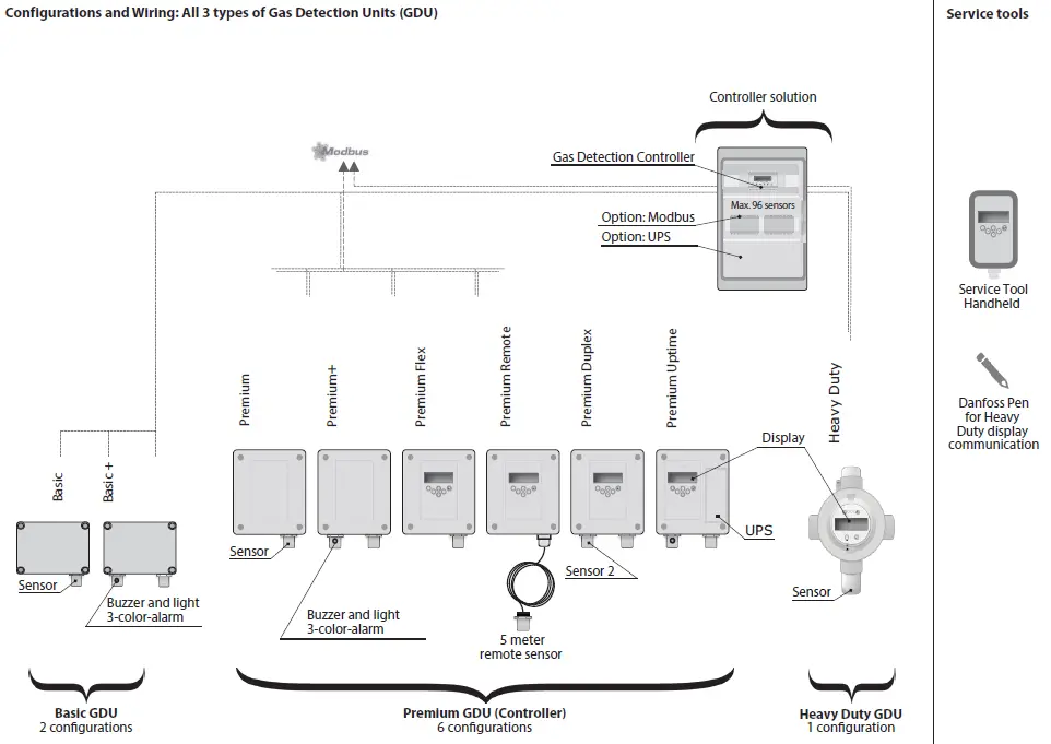
The Gas Detection Unit (GDU) comes in Basic and Premium configurations with various controller solutions. Follow the provided wiring diagrams for proper setup.
Technician use only!
- This unit must be installed by a suitably qualified technician who will install this unit by following these instructions and the standards set down in their particular industry/country.
- Suitably qualified operators of the unit should be aware of the regulations and standards set down by their industry/country for the operation of this unit.
- These notes are only intended as a guide, and the manufacturer is not responsible for the installation or operation of this unit.
- Failure to install and operate the unit by these instructions and with industry guidelines may cause serious injury, including death, and the manufacturer will not be held responsible in this regard.
- It is the installer’s responsibility to adequately ensure that the equipment is installed correctly and set up accordingly based on the environment and the application in which the products are being used.
- Please observe that a Danfoss GDU works as a safety device, securing a reaction to a detected high gas concentration. If a leakage occurs, the GDU will provide alarm functions, but it will not solve or take care of the leakage root cause itself.
Annual Test
- To comply with the requirements of EN378 and the F GAS regulation, sensors must be tested annually. Danfoss GDU’s are provided with a test button that should be activated once a year for testing of the alarm reactions.
- Additionally, the sensors must be tested for functionality by either a Bump test or Calibration. Local regulations should always be followed.
- After exposure to a substantial gas leak, the sensor should be checked and replaced if necessary.
- Check local regulations on calibration or testing requirements.
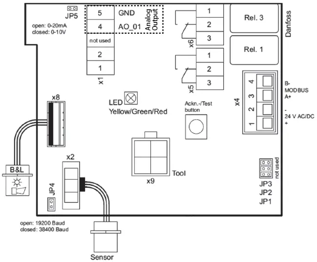
Danfoss Basic GDU
Status LED:
GREEN is power on.
YELLOW is an indicator of Error.
- When the sensor head is disconnected or not of the expected type
- AO is activated, but nothing is connected
- flashing when the sensor is in special mode (e.g., when changing parameters)
RED on alarm, similar to the Buzzer & light alarm.
Ackn. -/Test button:
TEST – The button must be pressed for 20 seconds.
- Alarm1 and Alarm2 are simulated, with a stop on release.
- ACKN. – Pressed while Alarm2, the audible warning switches off and goes back on after 5 min. When the alarm situation is still active. JP5 open → AO 4 – 20 mA (Default) JP5 closed → AO 2 – 10 Volt
NOTE:
A resistor comes installed on the analog output connections – if analog output is used, remove the resistor.
Status LED:
GREEN is power on.
YELLOW is an indicator of Error.
- When the sensor head is disconnected or not tof he expected type
- AO is activated, but nothing connected
RED on alarm, similar to the Buzzer & light alarm.
Ackn. -/Test button:
TEST – The button must be pressed for 20 seconds.
Alarm1 and Alarm2 are simulated, stoand p on release
ACKN.
Pressed while Alarm2, the audible warning switches off and goes back on after 5 minutes. When the alarm situation is still active.
JP2 closed → AO 2 – 10 Volt
NOTE:
A resistor comes installed on the analog output connections – if analog output is used, remove the resistor.
Danfoss Heavy Duty GDU (ATEX, IECEx approved)
On board LED is similar to the display LED:
Green is power on
Yellow is an indicator of Error
- When the sensor head is disconnected or not tof he expected type
- AO is activated, but nothing cisisnconnectedD onarm
On board Ackn. -/Test button:
- Test: The button must be pressed for 20 seconds.
- Alarm is simulated, stops on release.
Ackn.:
Pressed while Alarm2, the audible warning switches off and goes back on after 5 minutes. When the alarm situation is still active (also possible over the ESC button), use the magnetic Pen.
Location of Sensors
| Gas type | Relative density (Air = 1) | Recommended sensor location |
| R717 Ammonia | <1 | Ceiling |
| R744 CO | >1 | Floor |
| R134a | >1 | Floor |
| R123 | >1 | Floor |
| R404A | >1 | Floor |
| R507 | >1 | Floor |
| R290 Propane | >1 | Floor |
Gas Detection Controller: Fieldbus wiring – max 96 sensors in total, i.e., up to 96 GDU (Basic, Premium, and/or Heavy Duty)
Check for loop completion. Example: 5 x Basic in return loop
- Check of loop resistance: See section: Controller unit multiple GDU commissioning 2. NOTE: Remember to disconnect the wire from the board during measurement.
- Check of power polarity: See section: Controller unit multiple GDU commissioning 3.
- Check of BUS polarity: See section: Controller unit multiple GDU commissioning 3.
Individual Addresses for the GDU’s are given at commissioning, see Controller Unit multiple GDU’s commissioning, according to a predetermined “BUS address plan”
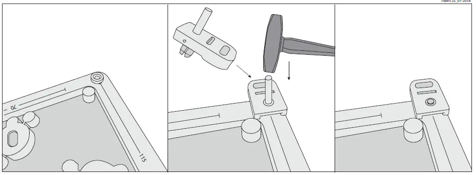
Attachment of suspension ears (Basic and Premium)
Cable Gland opening
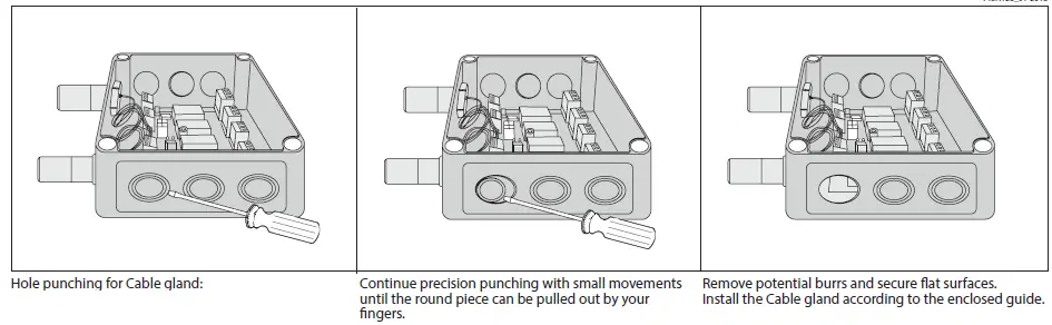
Hole punching for Cable gland:
- Select the location for the safest cable entry.
- Use a sharp screwdriver and a small hammer.
- Place the screwdriver and hammer with precision while moving the screwdriver within a small area until the plastic is penetrated.
Ambient conditions :
Please observe the ambient conditions speciÿed for each speciÿc GDU, as stated on the product. Do not install the units outside the given temperature and humidity range.
General GDU Mounting / Electrical wiring
- All GDU’s are for wall mounting
- Supporting ears are installed as shown in ÿg 9
- Cable entry is recommended on the box side. See ÿg 10
- Sensor position downwards
- Observe the possible constructors”instructions
- Leave the red protection cap (seal) on the sensor head until commissioning
When choosing the mounting site, please pay attention to the following:
- The mounting height depends on the relative density of the gas type to be monitored, see ÿg 6.
- Choose the mounting location of the sensor according to the local regulations
- Consider ventilation conditions. Do not mount the sensor close to air°ow (air passages, ducts, etc.)
- Mount the sensor at a location with minimum vibration and minimum temperature variation (avoid direct sunlight)
- Avoid locations where water, oil, etc., may in°uence proper operation and where mechanical damage might be possible.
- Provide adequate space around the sensor for maintenance and calibration work.
Wiring
The technical requirements and regulations for wiring, electrical security, as well as project speciÿc and environmental conditions etc. must be observed when mounting.
We recommend the following cable types˜
- Power supply for controller 230V at least NYM-J 3 x 1.5 mm
- Alarm message 230 V (also possible together with power supply) NYM-J X x 1.5 mm
- Signal message, bus connection to Controller Unit, warning devices 24 V J-Y(St)Y 2×2 x 0.8
- Possibly connected external analog transmitters J-Y(St)Y 2×2 x 0.8
- Cable for Heavy Duty: 7 – 12 mm diameter round cable
The recommendation does not consider local conditions such as ÿre protection, etc.
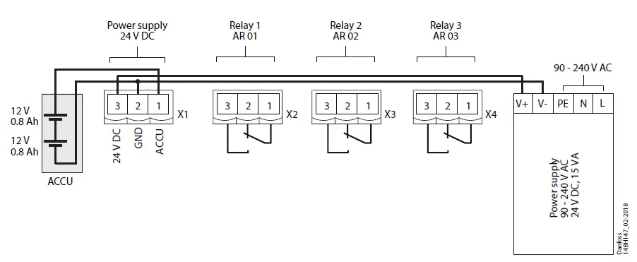
- The alarm signals are available as potential-free change-over contacts. If required the voltage supply is available at the power terminals.
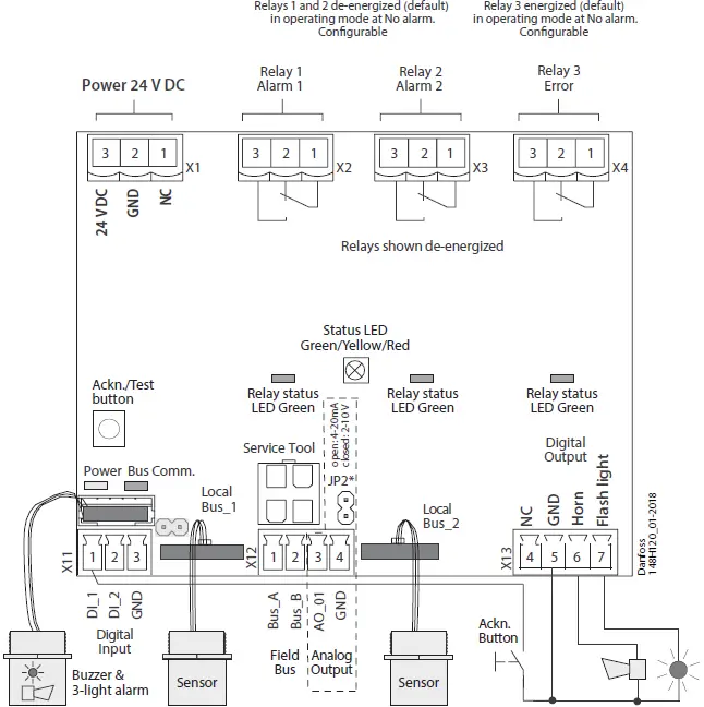
- The exact position of the terminals for the sensors and alarm relays is shown in the connection diagrams (see ÿgures 3 and 4).
Basic GDU
- The Basic GDU is designed for the connection of 1 sensor via the local bus.
- The GDU provides the power supply of the sensor and makes the measured data available for digital communication.
- Communication with the Controller Unit takes place via the RS 485 ÿeldbus interface with Controller Unit protocol.
- Other communication protocols for direct connection to superordinate BMS are available as well as Analog Output 4-20 mA.
- The sensor is connected to the local bus via a plug connection, enabling simple sensor exchange instead of an on-site calibration.
- The internal X-Change routine recognizes the exchanging process and the exchanged sensor and starts the measurement mode automatically.
- The internal X-change routine examines the sensor for actual type of gas and actual measuring range. If data does not match the existing conÿguration, the build in status LED indicates an error. If everything is OK the LED will light up green.
- For convenient commissioning, the GDU is pre-conÿgured and parameterized with factory-set defaults.
- As an alternative, the on-site calibration via the Controller Unit Service Tool can be performed with the integrated, userÿendly calibration routine.
For Basic units with Buzzer & Light, alarms will be given according to the following table:
Digital outputs
| Action | Reaction Horn | Reaction LED |
| Gas signal < alarm threshold 1 | OFF | GREEN |
| Gas signal > alarm threshold 1 | OFF | RED Slow blinking |
| Gas signal > alarm threshold 2 | ON | RED Fast blinking |
| Gas signal ≥ alarm threshold 2, but ackn. button pressed | OFF after delay ON | RED Fast blinking |
| Gas signal < (alarm threshold 2 – hysteresis) but >= alarm threshold 1 | OFF | RED Slow blinking |
| Gas signal < (alarm threshold 1 – hysteresis) but not acknowledged | OFF | RED Very fast blinking |
| No alarm, no fault | OFF | GREEN |
| No fault, but maintenance due | OFF | GREEN Slow blinking |
| Communication error | OFF | YELLOW |
Alarm thresholds can have the same valu;, thereforee the relays and/or Buzzer and LED can be triggered simultaneously.
Premium GDU (Controller)
- The Premium GDU is designed for the connection of maximum. Two sensors via the local bus.
- The controller monitors the measured values and activates the alarm relays if the set alarm thresholds for pre-alarm and main alert are exceeded. In addition, the values are provided for direct connection to the monitoring system (Controller Unit) via an RS-485 interface. Other communication protocols for direct connection to superordinate BMS are available, as well as Analog Output 4-20 mA.
- The SIL 2 compliant self-monitoring function in the Premium GDU and in the connected sensor activates the error message in case of an internal error as well as in case of an error in the local bus communication.
- The sensor is connected to the local bus via a plug connection, enabling simple sensor exchange instead of an on-site calibration.
- The internal X-Change routine recognizes the exchanging process and the exchanged sensor and starts the measurement mode automatically.
- The internal X-change routine examines the sensor for actual type of gas and actual measuring range and if data does not match the existing conÿguration, the build in status LED indicates an error. If everything is OK the LED will light up green.
- For convenient commissioning, the GDU is pre-conÿgured and parameterized with factory-set defaults.
- As an alternative, the on-site calibration via the Controller Unit Service Tool can be performed with the integrated, user-friendly calibration routine.
Digital outputs with three relays
|
Action |
Reaction | Reaction | Reaction | Reaction | Reaction | Reaction |
|
Relay 1 (Alarm1) |
Relay 2 (Alarm2) |
Flashlight X13-7 |
Horn X13-6 |
Relay 3 (Fault) |
LED |
|
| Gas signal < alarm threshold 1 | OFF | OFF | OFF | OFF | ON | GREEN |
| Gas signal > alarm threshold 1 | ON | OFF | OFF | OFF | ON | RED Slow blinking |
| Gas signal > alarm threshold 2 | ON | ON | ON | ON | ON | RED Fast blinking |
| Gas signal ≥ alarm threshold 2, but ackn. button pressed | ON | ON | ON | OFF after delay ON | RED Fast blinking | |
| Gas signal < (alarm threshold 2 – hysteresis) but >= alarm threshold 1 |
ON |
OFF |
OFF |
OFF |
ON |
RED Slow blinking |
| Gas signal < (alarm threshold 1 – hysteresis) but not acknowledged |
OFF |
OFF |
OFF |
OFF |
ON |
RED
Very fast blinking |
| No alarm, no fault | OFF | OFF | OFF | OFF | ON | GREEN |
|
No fault, but maintenance due |
OFF |
OFF |
OFF |
OFF |
ON |
GREEN
Slow blinking |
| Communication error | OFF | OFF | OFF | OFF | OFF | YELLOW |
Note 1:
Status OFF = Relay is configured “Alarm ON = Relay“ or the Premium Multi-Sensor-Controller is free from tension.
Note 2:
Alarm thresholds can have the same value; therefore, the relays and/or the horn and flashlight can be triggered together.
Relay Mode
Deÿnition of the relay operation mode. The terms energized / de-energized come from the terms energized /de-energized too trip principleopen-circuitt principle) used for safety circuits. The terms refer to the activation of the relay coil, not to the relay contacts (as they are executed as a changeover contact and available in both principles).
The LEDs attached to the modules show the two states in analogy (LED o˛ -> relay de-energized)
Heavy Duty GDU
- Approved according to ATEX and IECEx for zones 1 and 2.
- Permitted ambient temperature range: -40 °C < Ta < +60 °C
- Marking:
- Ex Symbol and
- II 2G Ex db IIC T4 Gb CE 0539
- Certiÿcation:
- BVS 18 ATEX E 052 X
- IECEx BVS 18.0044X
The Heavy Duty GDU is designed for the connection of 1 sensor via the local bus.
- The GDU provides the power supply of the sensor and makes the measured data available for digital communication. Communication with the Controller Unit takes place via the RS 485 ÿeldbus interface with Controller Unit protocol. Other communication protocols for direct connection to superordinate BMS are available as well as Analog Output 4-20 mA.
- The sensor is connected to the local bus via a plug connection, enabling simple sensor exchange instead of an on-site calibration.
- The internal X-Change routine recognizes the exchanging process and the exchanged sensor and starts the measurement mode automatically.
- The internal X-change routine examines the sensor for actual type of gas and actual measuring range. If data does not match the existing conÿguration, the build in status LED indicates an error. If everything is OK the LED will light up green.
- For convenient commissioning, the GDU is pre-conÿgured and parameterized with factory-set defaults.
- As an alternative, the on-site calibration via the Controller Unit Service Tool can be performed with the integrated, user-friendly calibration routine.
Installation Work
- Assembly work must only be carried out under gas-free conditions. The housing must neither be drilled nor be drilled through.
- The orientation of the GDU should always be vertical, with the sensor head pointing downwards.
- The mounting is done without opening the housing by using the two holes (D = 8 mm) of the fastening strap with suitable screws.
- The heavy-duty GDU must only be opened under gas-free and voltage-free conditions.
- The enclosed cable gland has to be checked for admissibility for the requested requirements before installation in position “Entry 3”. If the heavy-duty
- GDU is supplied without cable gland, a special cable gland approved for Ex protection class EXd and the requirements of the application havee to be mounted there.
- When inserting the cables, you have to strictly follow the instructions enclosed with the cable glands.
- No insulating sealing material must be poured into the NPT ¾ “threads of the cable gland and blanking plugs because the potential equalization between housing and cable gland / blind plugs is via the thread.
- The cable gland must be tightened ÿrmly with a suitable tool to torque 15 Nm. Only when doing so you can ensure the required tightness.
- After completion of work, the GDU must be closed again. The cover has to be completely screwed in and secured with the locking screw against inadvertent loosening.
General Notes
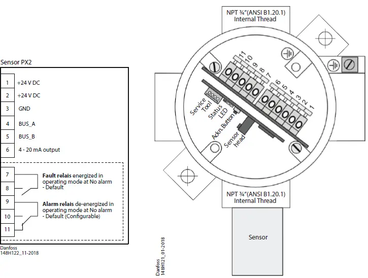
- The terminals of the heavy-duty GDU are located behind the display.
- Only a professional should perform the wiring and the connection of the electrical installation according to the wiring diagram in compliance with the relevant regulations, and only when de-energized!
- When connecting cables and conductors, please observe a minimum length of 3 m according to EN 60079-14.
- Connect the housing to the equipotential bonding via the external ground terminal.
- All terminals are Ex e type with spring contact and push actuation. The permissible conductor cross section is 0.2 to 2.5 mm˘ for single wires and multi-wire cables.
- Use cables with a braided shield for compliance with the interference immunity. The shield must be connected to the inside connection of the housing with a maximum length of about 35 mm.
- For the recommended cable types, cross sections, and lengths, please refer to the table below.
- To comply with the requirements of servicing or operating the device without opening it (EN 60079-29- 1 4.2.5), it is possible to calibrate or operate the device remotely via the central bus. FIt snecessary to lead the central bus out to the safe area via a cable.
Further Notes and Restrictions
- The maximum operating voltage and the terminal voltage of the relays have to be limited to 30 V by adequate measures.
- The maximum switching current of the two relay contacts should be limited to 1 A by appropriate external measures.
- Repairs to °ameproof joints are not intended and lead to the immediate loss of the type approval for the pressure-resistant casing.
| Cross-section (mm )Max. | x. length for 24 V DC1 (m) | |
| With P, freon sensor heads | ||
| Operating voltage with a 4–20 mA signal | 0.5 | 250 |
| 1.0 | 500 | |
| Operating voltage with central bus 2 | 0.5 | 300 |
| 1.0 | 700 | |
| With SC, EC sensor heads | ||
| Operating voltage with a 4–20 mA signal | 0.5 | 400 |
| 1.0 | 800 | |
| Operating voltage with central bus 2 | 0.5 | 600 |
| 1.0 | 900 | |
- The max. Cable lengths and our recommendation don’t consider any local conditions, like ÿre protection, national regulations, etc.
- For the central bus, we recommend using the cable JE-LiYCY 2x2x0.8 BD or 4 x2x0.8 BD.
Commissioning
- For sensors that can be poisoned by e.g. silicones like all semiconductor and catalytic bead sensors, it is imperative to remove the protective (seal) cap supplied only after all silicones are dry, and then energize the device.
- For fast and comfortable commissioning we recommend proceeding as follows. For digital devices with self-monitoring all internal errors are visible via the LED. All other error sources often have their origins in the eld, because it is here where most of the causes for problems in the ÿeld bus communication appear.
Optical Check
- The right cable type is used.
- Correct mounting height according to deÿnition in Mounting.
- Led status
Comparing sensor gas type with GDU default settings
- Each sensor ordered is speciÿc and must match the GDU default settings.
- The GDU software automatically reads the speciÿcation of the connected sensor and compares it with the GDU settings.
- If other gas sensor types are connected, you have to adjust them with the conÿguration tool, because otherwise the device will respond with an error message.
- This feature increases the user and operating security.
- New sensors are always delivered factory-calibrated by Danfoss. This is documented by the calibration label indicating date and calibration gas.
- A repeated calibration is not necessary during commissioning if the device is still in its original packaging (air-tight protection by the red protective cap) and the calibration doesn’t date back more than 12 months.
Functional test (for initial operation and maintenance)
- The functional test should be carried out during each service, but at least once a year.
- Functional test is done by pressing the test button for more than 20 sec and observing all connected outputs (Buzzer, LED, Relay connected devices) working properly. After deactivation, all outputs must automatically return to their initial position.
- Zero-point test with fresh outdoor air
- Zero-point test with fresh outdoor air. (If prescribed by local regulations) A potential zero o˛set can be read out by use of the Service tool.
Trip test with reference gas (If prescribed by local regulations)
- The sensor is gassed with reference gas (for this, you need a gas bottle with a pressure regulator and a calibration adapter).
- In doing so, the set alarm thresholds are exceeded, and all output functions are activated. It is necessary to check if the connected output functions are working correctly(the horn sounds, the fan switches on, and devices shut down). By pressing the push-button on the horn, the horn acknowledgment must be checked
- . After the removal of the reference gas, all outputs must automatically return to their initial position.
- Other than the simple functional testing, it is also possible to perform a functional test using calibration. For further information, please refer to the User Manual.
Controller Unit multiple GDU commissioning
For fast and comfortable commissioning we recommend proceeding as follows. Especially the given speciÿcations of the ÿeld bus cable have to be checked carefully, because it is here where most of the causes for problems in the ÿeld bus communication appear.
Optical Check
- The right cable type is used (JY(St)Y 2x2x0.8LG or better).
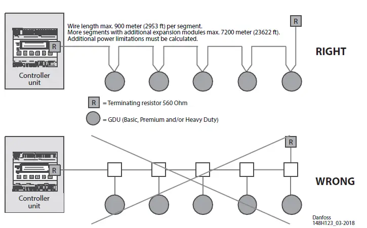
- Cable topology and cable length.
- Correct mounting height of the sensors
- Correct connection at each GDU according to ÿg 8
- Termination with 560 ohms at the beginning and the end of each segment.
- Pay special attention so that the polarities of BUS_A and BUS_B are not reversed!
Check Short-circuit / Interruption / Cable Length of the Field Bus (see ÿg8.1)
- This procedure has to be executed for each segment.
- The ÿeld bus cable must be laid at the connector terminal block of the GDU for this testing. The plug, however, is not yet plugged into the GDU.
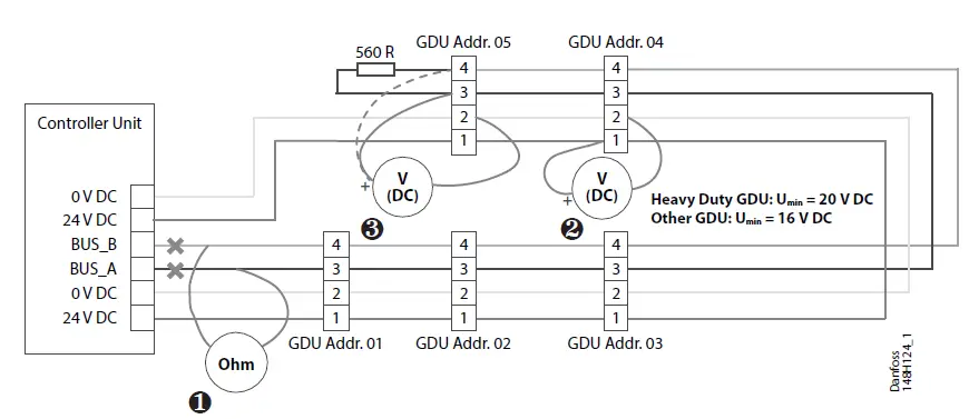
Disconnect the ÿeld bus leads from the Controller Unit central control. Connect the ohmmeter to the loose leads and measure the total loop resistance. See ÿg. 8.1 The total loop resistance is calculated as follows:
- R (total) = R (cable) + 560 Ohm (terminating resistance)
- R (cable) = 72 Ohm/km (loop resistance) (cable type JY(St)Y 2x2x0.8LG)
| R (total) (ohm) | Cause | Troubleshooting |
| < 560 | Short-circuit | Look for a short circuit in the field bus cable. |
| infinite | Open-circuit | Look for the interruption in the field bus cable. |
| > 560 < 640 | Cable is o.k. | — |
The allowed cable length can be calculated in a sufficiently exact way according to the following formula.
- Total cable length (km) = (R (total) – 560 Ohm) / 72 Ohm
- If the ÿeld bus cable is OK, reconnect it to the central unit.
Check Voltage and Bus Polarity of the Field Bus (see ÿg 8.2 and 8.3)
- The bus connector is to be plugged into each GDU.
- Switch the operating voltage on at the Controller Unit central unit.
- The green LED at the GDU lights up weakly when the operating voltage is applied (voltage indicator).
- Check operating voltage and bus polarity at each GDU according to ÿg. 7.1 and 7.2. Umin = 16 V DC (20 V DC for Heavy Duty)
Bus polarity:
Measure tension BUS_A against 0 V DC and BUS_B against 0 V DC. U BUS_A = ca. 0.5 V > U BUS_B
U BUS_B = ca. 2 – 4 V DC (depending on the number of GDU and the cable length)
Addressing the GDU
- After having checked the ÿeld bus successfully, you have to assign a basic communication address to each GDU via the display on the unit, the service tool or the PC tool.
- With this basic address, the data of the Sensor Cartridge assigned to input 1 are sent via the ÿeld bus to the gas controller.
- Any further sensor connected / registered on the GDU automatically gets the next address.
- Choose the menu Address and enter the predetermined Address according to the Bus Address Plan.
- If this connection is OK, you can read the current GDU address in the menu “Address“ either at the display on the unit or by plugging in the service tool or the PC tool.
0 = Address of new GDU - XX = Current GDU address (permissible address range 1 – 96)
The detailed description of the addressing can be taken from the user manual of the Controller unit or the Controller unit service tool.
Further documentation:

Climate Solutions • danfoss.com • +45 7488 2222
- Any information, including, but not limited to, information on the selection of the product, its application, or use. Product design, wei ht, dimensions, capacity or any other technical data in product manuals, catalogues descriptions, advertisements, etc. and whether made available in writing, orally, electronically, online or via down oad, shall be considered informative, and aree only binding if and to the extent, explicit reference is made in a quotation or order confirmation.
- Danfoss cannot accept any responsibility for possible errors in catalogues, brochures, videos, and other material.
- Danfoss reserves the right to alter its products without notice. This also applies to products ordered but not delivered, provided that such alterations can be made without changes to the form, fit, or
function of the product. - All trademarks in this material are the property of Danfoss A/S or Danfoss group companies. Danfoss and the Danfoss logo are trademarks of Danfoss A/S, A1 rights reserved.
- AN272542819474en-000402
- Danfoss I Climate solutions j 2024.02
FAQs
- Q: How often should sensors be tested?
A: Sensors must be tested annually to comply with regulations. - Q: What should be done after a substantial gas leak?
A: After a substantial gas leak exposure, sensors should be checked and replaced if necessary. Follow local regulations for calibration or testing requirements.
Documents / Resources
 |
Danfoss GDU Gas Detection Unit [pdf] Installation Guide GDA, GDC, GDHC, GDHF, GDH, GDU Gas Detection Unit, Gas Detection Unit, Detection Unit, Unit |