
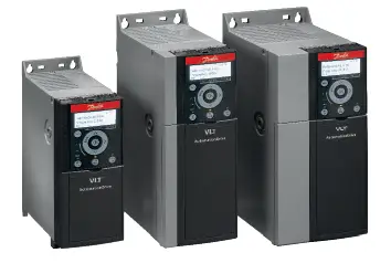
Danfoss FC 360 VLT Automation VFD AC Drives

Product Information
Specifications
- Power Output: 315 kW
- Industrial Applications: Suitable for all
- Control Range: 0.37 kW to 315 kW
- Harmonics Reduction: 40-48% THDi with built-in DC choke
- Coating: High quality, advanced coating for protection in challenging environments
- Protection Level: IP20 standard protection
- Display: Enhanced numerical display or graphical control panel supporting English, Chinese, and Portuguese
- Cooling: Unique cooling concept with no forced air flow over electronics
Product Usage Instructions
Installation
The compact design allows for easy installation. Mount the drive in an IP20 enclosure with zero clearance for side-by-side mounting.
Parameter Setup
Set up parameters easily using the enhanced numeric LCP or graphical control panel. Targeted ‘Application Selections’ simplify commissioning for typical applications.
Maintenance
Regular cleaning is essential. Use the easy-to-remove fan to prevent dust accumulation and ensure proper ventilation.
Cooling System
The unique cooling concept prevents forced air flow over electronics, reducing downtime and improving stability. Ensure separation between back-channel cooling air and internal electronics for efficient cooling.
FAQ
- Q: What industrial applications is this product optimized for?
- A: The product is optimized for various industrial applications including extruders, escalators, winders, material handling, stacking machines, shelf lifts, and more.
- Q: How can I reduce harmonics in my system?
- A: The built-in DC choke reduces harmonics to 40-48% THDi, providing a solution to reduce harmonics in your system.
- Q: What languages are supported on the control panel?
- A: The control panel supports English, Chinese, and Portuguese languages for user convenience.
Selection guide | VLT® Automation Drive FC 360 | 0.37 – 315 kW
High performance in challenging environments
Built to last, VLT® Automation Drive FC 360 operates effectively and reliably even in the most challenging environments and applications.
Danfoss Drives · AD461136013340en-000302
- Built on the success of the tried and tested VLT® platform that Danfoss developed and launched in the
1960’s, the VLT® AutomationDrive - FC 360 shares the same technical heritage as the popular and versatile VLT® AutomationDrive FC 300 series. Developed to meet a general purpose operation profile the drive lacks the expandability of its larger sibling, but still delivers powerful performance out of the box.
- Because all Danfoss drives follow the same basic design and operating principle, existing owners and users of VLT® drives will instantly feel at home with the FC 360.
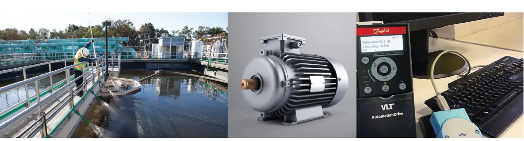
The FC 360 is a dedicated industry drive. It provides precise and efficient motor control in a wide range of industrial applications.
Built-in features help owners save
- Installation space
- Setup time
- Maintenance time
The result is a powerful and versatile solution that increases process efficiency and quality in a cost-efficient package.
Built-in features facilitate high performance and fewer external components.
This reduces complexity and makes the ordering process easier.
Reduced Harmonics
A built-in DC choke reduces harmonics to 40-48% THDi and significantly extends the lifetime of the DC capacitor.
Designed for challenging environments
The internal electronics of the FC 360 are protected by a high quality, advanced coating. This coating provides the rugged characteristics demanded by the textile, plastics, rubber, food, beverage, and building materials industries.
Maximize productivity
IP20 standard protection and an
easy-to-use control panel saves valuable time in commissioning and maintenance, and enables owners to maximize uptime and conserve energy.
Compact design for easy installation
The compact, lightweight design enables owners to optimize panel space by mounting several drives side-by-side mounting with zero clearance.
Save time on setup
Easy parameter setup makes the path to energy savings both short and simple, and can be carried out with an enhanced numeric LCP or graphical control panel that supports English, Chinese and Portuguese. Targeted ‘Application Selections’ make it easy for users to set up and commission typical applications.
High reliability
- Coated printed circuit boards
High level 3C3 Printed Circuit Board (PCB) coating as standard provides high reliability in harsh environments to prevent failures and downtime. The lifetime of the drive is also increased as a result of the IEC 60721-3-3 conformal coating. - 55 °C working temperature
VLT® AutomationDrive FC 360 is designed to operate at 45-50° C ambient temperature at full load (depending on model) and 55° C with derating. This means there is no need to install extra cooling equipment or over-dimension the drive, resulting in cost savings. - Efficient heat management
A unique cooling concept ensures that there is no forced air flow over the electronics. This reduces the risk of downtime, while strengthening stability in daily operation.
By preventing dust and particles from accumulating on the small internal components and legs, the risk of short circuits is significantly reduced, especially in humid environments.
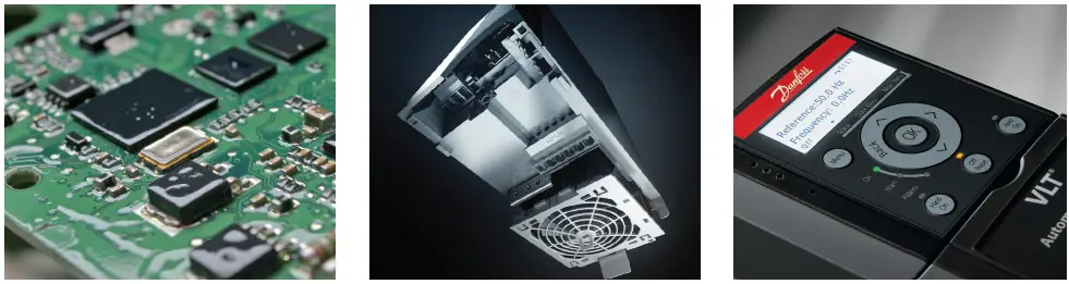
Coated PCB
The VLT® AutomationDrive FC 360 is delivered with a 3C3 class coated PCB as standard to strengthen reliability.
Easy cleaning
An easy-to-remove fan makes it easy to keep dust from affecting the drive’s ventilation.
Display
Customer can select an enhanced numerical display or graphical control panel that supports English, Chinese and Portuguese.
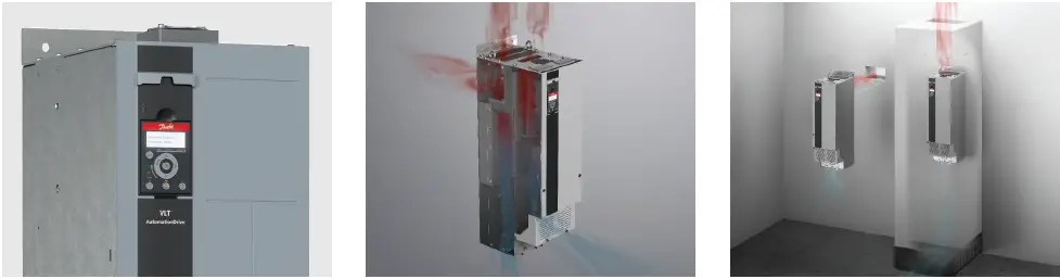
Enclosure
The VLT® AutomationDrive FC 360 is available with an IP20 enclosure.
Separation
Total separation between the back-channel cooling air and the internal electronics to ensure efficient cooling
Rear air cooling channel
By directing air through a rear cooling channel up to 90% of the drive’s heat loss is removed directly outside the installation room.
Optimized for industrial applications
- Extruders
- Escalators
- Winders
- Material handling
- Stacking machine
- Shelf lift
- Rail-guided vehicle (RGV)
- Conveyor
- Draw bench
- Textile machinery
- Petrochemical
- Hoist
- Air compressor
- Printing & dyeing
- Glass production line
- Centrifuge separators
- Pumps
- Fans
- Mixers
High Performance Controller
- VLT® AutomationDrive
- FC 360 has an advanced controller with a high speed response, making high-end, complicated applications easy.
- 450 kg force at 0.6 Hz. The high torque performance of a 0.75 kW VLT® AutomationDrive
- FC 360 fully meets the demands for tensile testing at Samaya Technocrats in India.
Speed
Expand with control and feedback modules
Fieldbus communication in the VLT® AutomationDrive FC 360 is integrated in the control card. In addition, the drive can be expanded with options for additional control and encoder feedback.
With the VLT® Encoder Input MCB 102 and VLT® Resolver Input MCB 103 the VLT® AutomationDrive FC 360 can receive encoder feedback from either a motor or a process.
Time-saving setup VLT® Motion Control Tool MCT 10
- The FC 360 can be configured and monitored with Danfoss’ own VLT® Motion Control Tool MCT 10 software. This provides plant managers with a comprehensive overview of the system at any point in time and a high level of flexibility in configuration and monitoring.
- MCT 10 is a Windows-based engineering tool with a clearly structured interface that provides an instant overview of all the drives in a system of any size. The software runs under Windows and enables data exchange over a traditional RS 485 interface or fieldbus (PROFIBUS/PROFINET).
- Parameter configuration is possible both online and offline, and the software can be configured to link to the system’s electrical diagrams or operating manuals. This helps to reduce the risk of incorrect configuration while offering fast access to troubleshooting.
Use with VLT® OneGearDrive®
The VLT® AutomationDrive FC 360 is designed to work perfectly with permanent magnet motors, such as the VLT® OneGearDrive®, which is widely used in the Danfoss VLT® FlexConcept®.
Easy Setup via PC
Connect the VLT® AutomationDrive FC 360 directly to a PC for fast and easy transfer of settings.
- Built-in brake chopper
A built-in brake chopper up to 22 kW saves money and panel space. - Pulse input as speed reference
Convert pulse input as a speed reference, avoiding the need to purchase an analog signal module for PLC. - Built-in PID controller
The built in PID controller calculates an ‘error’ value as the difference between a measured process variable and a desired setpoint. - Built-in RFI filter
Built-in filters not only save space, but also eliminate additional costs for fitting, wiring, and material. The most important advantage is the perfect EMC conformance and cabling of integrated filters. - Positioning
With the integrated encoder input or MCB option, the positioning control includes features such as homing, position-reference setting, position feedback and PID control. It supports both absolute positioning and relative positioning applications, such as stacking machines, shelf lifts or rail-guided vehicles. - Torque closed-loop control
Torque closed-loop control actualizes the functionality through encoder feedback; both terminal 32/33 pulse inputs and MCB102 inputs are available. - PM motor control
The FC 360 supports synchronous motor control, including Surface Placed Magnets (SPM) and Interior Placed Magnets (IPM).
Communicative
The FC 360 communicates using your preferred choice of process automation protocols
- PROFIBUS
- PROFINET with dual port
- Modbus RTU and FC Protocol are integrated as standard
Designed for a wide range of power supply conditions, the FC 360 can operate at -15% of supply voltage

- Designed for use in ambient temperatures up 40-50 °C without derating. Max. ambient temperature 55 °C
- No forced air over PCB for whole power range
- Class 3C3 coated components for increased reliability in harsh environments (IEC 60721-3-3)
- Removable fan
- Integrated EMC filter
- Built-in brake chopper up to 22 kW
- Fieldbus embedded in control card (FC Protocol, Modbus RTU, Options: PROFIBUS and PROFINET)
- I/O number and functions
- 7DI / 2AI / 2AO / 2 DO
- Pulse input as speed reference
- Pulse feedback and 24 V encoder feedback
- 24 V (100 mA)
- 12 V
- 9 Display options
- Graphic LCP
- Enhanced numeric LCP
- Blind cover
- Fully automatic motor adaptation (AMA) optimizes compatibility between drive and motor in VVC+ mode
- Built-in Smart Logic Controller
- RFI Swich
Specification
(Basic unit without extensions)
| Main supply (L1, L2, L3) | |
| Supply voltage | J1-J7: 380-480 V -15%/+10% J8-J9: 380-480 V -10%/+10% |
| Supply frequency | 50/60 Hz ±5% |
| Displacement power factor (cos ) | > 0.98 |
| Switching on input supply L1, L2, L3 | 0.37-7.5 kW maximum 2 times/min.
11-315 kW maximum 1 time/min. |
| Harmonic disturbance | Meets EN 61000-3-12 |
| Output data (U, V, W) | |
| Output voltage | 0-100% of supply voltage |
| Output frequency | Induction motor:
V/F mode: 0-500 Hz VVC+ mode: 0-200 Hz Flux basic mode: 0-200 Hz PM motor: VVC+ mode: 0-400 Hz Flux basic mode: 0-300 Hz |
| Switching on output | Unlimited |
| Ramp times | 0.01-3600 sec |
Note: 150%/110% current can be provided for 1 minute. Higher overload rating is achieved by oversizing the drive.
| Digital inputs | |
| Programmable digital inputs | 7 |
| Changeable to digital output | 2 (Terminal 27,29) |
| Logic | PNP or NPN |
| Voltage level | 0 – 24 V DC |
| Maximum voltage on input | 28 V DC |
| Input resistance, Ri | Approx. 4 k0 |
| Scan interval | 1 ms |
* 2 can be used as digital outputs
| Analog inputs | |
| Analogue inputs | 2 |
| Modes | Voltage or current |
| Voltage level | 0 to +10 V (saleable) |
| Current level | 0/4 to 20 mA (saleable) |
| Accuracy of analog inputs | Max. error 0.5% of full scale |
| Pulse/encoder inputs | |
| Programmable pulse/ encoder inputs | 2/1 |
| Voltage level | 0 – 24 V DC (PNP positive logic) |
| Pulse input accuracy (0.1 – 1 kHz) | Max. error: 0.1% of full scale |
| Encoder input accuracy | 4 Hz-32 kHz |
Utilize some of the digital inputs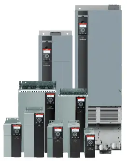
| Digital outputs | |
| Programmable digital/pulse outputs | 2 |
| Voltage level at digital/frequency output | 0-24 V DC |
| Max. output current (sink or source) | 40 mA |
| Maximum output frequency at frequency output | 4 Hz to 32 kHz |
| Accuracy on frequency output | Max. error: 0.1% of full scale |
Utilize 2 digital inputs
| Analogue output | |
| Programmable analogue outputs | 2 |
| Current range at analogue output | 0/4 – 20 mA |
| Max. load to common at analogue output (clamp 30) | 500 0 |
| Accuracy on analogue output | Max. error: 0.8 % of full scale |
| Control card | |
| RS485 interface | Up to 115 kBaud |
| Max. load (10 V) | 15 mA |
| Max. load (24 V) | 100 mA |
| Relay output | |
| Programmable relay outputs | 2 |
| Max. terminal load (AC) on 1-3 (break), 1-2 (make), 4-6 (break) power card |
250 V AC, 3 A |
| Max. terminal load (AC) on 4-5 (make) power card | 250 V AC, 3 A |
| Min. terminal load on 1-3 (break), 1-2 (make),
4-6 (break), 4-5 (make) power card |
250 V AC, 0.2 A |
| Surroundings/external | |
| Enclosure | IP20 |
| Vibration test | 1.0 g |
| Max. relative humidity | 5-95% (IEC 60721-3-3; Class 3K3
(non-condensing) during operation |
| Ambient temperature | 40-50 °C |
| Galvanic isolation of all | I/O supplies according to PELV |
| Aggressive environment | Class 3C3 |
| Fieldbus communication | |
| Standard built-in | FC Protocol Modbus RTU |
| Fieldbus built-in control card variants | PROFIBUS or PROFINET |

Connection examples
The numbers represent the terminals on the drive

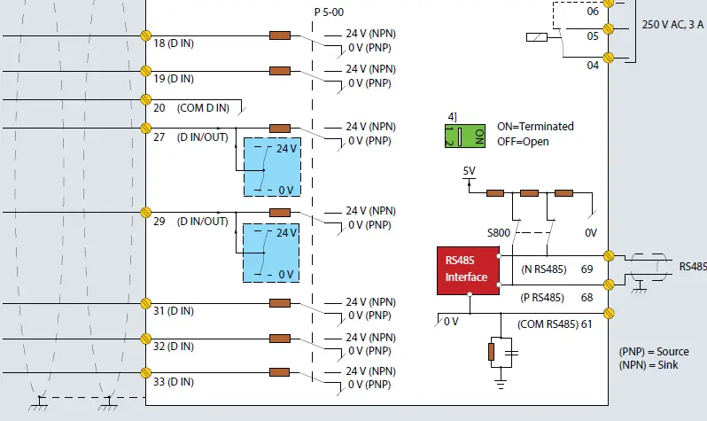
- Built-in brake chopper available from J1–J5.
- Relay 2 is 2-pole for J1–J3 and 3-pole for J4–J9. Relay 2 of J4–J9 with terminals 4, 5, and 6 has same NO/NC logic as relay 1. Relays are plug-gable in J1–J5, and fixed in J6–J7
- Single DC choke in J1–J5, Dual DC choke in J6–J9.
- Switch S800 (bus terminal) can be used to en-able termination on the RS485 port (terminals 68 and 69).
- No BR for J6–J9.
- No terminal 81, 88 and 89 for J8 and J9
- The diagram shows the port terminals of the VLT® AutomationDrive FC 360.
- The numbers indicated refer to the terminal numbers of the drives.
- Set the mode of the analogue inputs 53 and 54 by setting software parameters.
- The FC 360 features a RS485 interface as standard. The RS485 terminations are integrated in the drive (S800).
- PROFIBUS DP or PROFINET can be specified by configuring different control cassette when ordering.
- To switch from NPN to PNP logic for the digital signals, use parameter 5-00.
Ordering model code and electrical data

| [1] Application | |
| 360 | VLT® AutomationDrive FC 360 |
| [2] Power Size | |
| HK37/ QK37 | See ratings data on page 12-13 for power ratings |
| HK55/ QK55 | |
| HK75/ QK75 | |
| H1K1/ Q1K1 | |
| H1K5/ Q1K5 | |
| H2K2/ Q2K2 | |
| H3K0/ Q3K0 | |
| H4K0/ Q4K0 | |
| H5K5/ Q5K5 | |
| H7K5/ Q7K5 | |
| H11K/ Q11K | |
| H15K/ Q15K | |
| H18K/ Q18K | |
| H22K/ Q22K | |
| H30K/ Q30K | |
| H37K/ Q37K | |
| H45K/ Q45K | |
| H55K/ Q55K | |
| H75K/ Q75K | |
| H90K/ Q90K | |
| H110/ Q110 | |
| H132/ Q132 | |
| H160/ Q160 | |
| H200/ Q200 | |
| H250/ Q250 | |
| Q315 | |
| [3] AC Line Voltage | |
| T4 | 3 x 380/480 V AC (high overload)
3 x 380/480 V AC (normal overload) |
| [4] Enclosure | |
| For cabinet mounting: | |
| E20 | IP20/Chassis |
| [5] RFI Filter (EN 55011) | |
| H2 | RFI-Filter, Class A2 (C3) |
| [6] Braking | |
| X | No brake IGBT |
| B | Built-in brake IGBT 1] |
| [7] Display (Local Control Panel) | |
| X | No LCP, blind cover 2] |
| [8] Conformal coating (IEC 60721-3-3) | |
| C | Conformal coating on all PCBs |
| [9] Mains Input | |
| X | No mains option 3] |
| D | Load-sharing terminals |
| [10] Cable | |
| X | Standard cable entry |
| [13] Fieldbus embedded in control cassette 4] | |
| AX | No fieldbus option |
| A0 | PROFIBUS |
| AL | PROFINET |
| [14] B Option (Application) | |
| BX | No application option5] |
- 0.37-22kW built-in; 30-315 kW without brake IGBT
- Following accessories available: Numeric and graphical LCP and blind cover
- J8, J9 has no mains option
- Normal overload products are available in AX and AL versions only
- VLT® Encoder Input MCB 102, VLT® Resolver Input MCB 103 and VLT® Sensor Input MCB 114 available as accessories
380-480 V AC
| Enclosure | IP20 | J1 | J2 | J3 | |||||||||
| HO1] | HK37 | HK55 | HK75 | H1K1 | H1K5 | H2K2 | H3K0 | H4K0 | H5K5 | H7K5 | |||
| (NO)1] | QK37 | QK55 | QK75 | Q1K1 | Q1K5 | Q2K2 | Q3K0 | Q4K0 | Q5K5 | Q7K5 | |||
| Typical shaft output | [kW] | 0.37 | 0.55 | 0.75 | 1.1 | 1.5 | 2.2 | 3 | 4 | 5.5 | 7.5 | ||
| Typical shaft output at 460 V | [HP] | 0.5 | 0.75 | 1 | 1.5 | 2 | 3 | 4 | 5.5 | 7.5 | 10 | ||
| Output current
(3 x 380-440 V) |
Continuous | [A] | 1.2 | 1.7 | 2.2 | 3 | 3.7 | 5.3 | 7.2 | 9 | 12 | 15.5 | |
| Output current
(3 x 441-480 V) |
Continuous | [A] | 1.1 | 1.6 | 2.1 | 3 | 3.4 | 4.8 | 6.3 | 8.2 | 11 | 14 | |
| Intermittent
(60 s overload) |
HO | [A] | 1.9 | 2.7 | 3.5 | 4.8 | 5.9 | 8.5 | 11.5 | 14.4 | 19.2 | 24.8 | |
| NO | 1.3 | 1.9 | 2.4 | 3.3 | 4.1 | 5.8 | 7.9 | 9.9 | 13.2 | 17.1 | |||
| Output power
(400 V AC) |
Continuous | [kVA] | 0.8 | 1.2 | 1.5 | 2.1 | 2.6 | 3.7 | 5.0 | 6.2 | 8.3 | 10.7 | |
| Output power
(460 V AC) |
Continuous | [kVA] | 0.9 | 1.3 | 1.8 | 2.5 | 2.8 | 4 | 5.2 | 6.8 | 9.2 | 11.6 | |
| Max. cable size
(Mains, motor, brake and load sharing) |
[mm2] ([AWG]) | 4 mm2 | |||||||||||
| Max. input current
(3 x 380-440 V) |
Continuous | [A] | 1.2 | 1.6 | 2.1 | 2.6 | 3.5 | 4.7 | 6.3 | 8.3 | 11.2 | 15.1 | |
| Max. input current
(3 x 441-480 V) |
Continuous | [A] | 1 | 1.2 | 1.8 | 2 | 2.9 | 3.9 | 4.3 | 6.8 | 9.4 | 12.6 | |
| Intermittent
(60 s overload) |
HO | [A] | 1.9 | 2.6 | 3.4 | 4.2 | 5.6 | 7.5 | 10.1 | 13.3 | 17.9 | 24.2 | |
| NO | 1.3 | 1.8 | 2.3 | 2.9 | 3.9 | 5.2 | 6.9 | 9.1 | 12.3 | 16.6 | |||
| Max. pre-fuses | [A] | 10 | 25 | 32 | |||||||||
| Estimated power loss at rated max. load | [W] | 20.8 | 25.1 | 30 | 40 | 52.9 | 73.9 | 94.8 | 115.5 | 157.5 | 192.8 | ||
| Weight (IP20) | [kg] | 2.3 | 2.3 | 2.3 | 2.3 | 2.3 | 2.5 | 3.6 | 3.6 | 3.6 | 4.1 | ||
| [lb] | 5.1 | 5.1 | 5.1 | 5.1 | 5.1 | 5.5 | 7.9 | 7.9 | 7.9 | 9.0 | |||
| Effciency | 0.96 | 0.97 | 0.98 | ||||||||||
HO: High overload 150% 1 min/10 min
NO: Normal overload 110% 1 min/10 min
380-480 V AC
| Enclosure | IP20 | J4 | J5 | J6 | |||||
| HO1] | H11K | H15K | H18K | H22K | H30K | H37K | H45K | ||
| (NO)1] | Q11K | Q15K | Q18K | Q22K | Q30K | Q37K | Q45K | ||
| Typical shaft output | [kW] | 11 | 15 | 18 | 22 | 30 | 37 | 45 | |
| Typical shaft output at 460 V | [HP] | 15 | 20 | 25 | 30 | 40 | 50 | 60 | |
| Output current
(3 x 380-440 V) |
Continuous | [A] | 23 | 31 | 37 | 42.5 | 61 | 73 | 90 |
| Output current
(3 x 441-480 V) |
Continuous | [A] | 21 | 27 | 34 | 40 | 52 | 65 | 80 |
| Intermittent
(60 s overload) |
HO | [A] | 34.5 | 46.5 | 55.5 | 63.8 | 91.5 | 109.5 | 135 |
| NO | 25.3 | 34.1 | 40.7 | 46.8 | 67.1 | 80.3 | 99 | ||
| Output power
(400 V AC) |
Continuous | [kVA] | 15.9 | 21.5 | 25.6 | 29.5 | 42.3 | 50.6 | 62.4 |
| Output power
(460 V AC) |
Continuous | [kVA] | 17.5 | 22.5 | 28.3 | 33.3 | 43.2 | 54 | 66.5 |
| Max. cable size
(Mains, motor, brake) |
[mm2] ([AWG]) | 16 mm2 | 50 mm2 | ||||||
| Max. input current
(3 x 380-440 V) |
Continuous | [A] | 22.1 | 29.9 | 35.2 | 41.5 | 57 | 70.3 | 84.2 |
| Max. input current
(3 x 441-480 V) |
Continuous | [A] | 18.4 | 24.7 | 29.3 | 34.6 | 49.2 | 60.6 | 72.2 |
| Intermittent
(60 s overload) |
HO | [A] | 33.2 | 44.9 | 52.8 | 62.3 | 85.5 | 105.45 | 126.3 |
| NO | 24.3 | 32.9 | 38.7 | 45.7 | 62.7 | 77.3 | 92.6 | ||
| Max. pre-fuses | [A] | 50 | 80 | 160 | |||||
| Estimated power loss at rated max. load | [W] | 289.5 | 393.3 | 402.8 | 467.5 | 630 | 848 | 1175 | |
| Weight (IP20) | [kg] | 9.4 | 9.5 | 12.3 | 12.5 | 22.4 | 22.5 | 22.6 | |
| [lb] | 20.7 | 20.9 | 27.1 | 27.6 | 49.4 | 49.6 | 49.8 | ||
| Efficiency | 0.98 | ||||||||
HO: High overload 150% 1 min/10 min
NO: Normal overload 110% 1 min/10 min
380-480 V AC
| Enclosure | IP20 | J7 | J8 | J9 | |||||||||
| HO1] | H55K | H75K | H90K | H110 | H132 | H160 | H200 | H250 | |||||
| (NO)1] | Q55K | Q75K | Q90K | Q110 | Q132 | Q160 | Q200 | Q250 | Q315 | ||||
| Typical shaft output | [kW] | 55 | 75 | 90 | 90 | 110 | 132 | 160 | 160 | 200 | 250 | 315 | |
| Typical shaft output at 460 V | [HP] | 75 | 100 | 125 | 125 | 150 | 200 | 250 | 250 | 300 | 350 | 450 | |
| Output current
(3 x 380-440 V) |
Continuous | [A] | 106 | 147 | 177 | 177 | 212 | 260 | 315 | 315 | 395 | 480 | 588 |
| Output current
(3 x 441-480 V) |
Continuous | [A] | 96 | 124 | 160 | 160 | 190 | 240 | 302 | 302 | 361 | 443 | 535 |
| Intermittent
(60 s overload) |
HO | [A] | 159 | 220.5 | 195 | 266 | 318 | 390 | 347 | 473 | 593 | 720 | 647 |
| NO | 116.6 | 161.7 | 195 | 266 | 233 | 286 | 347 | 473 | 435 | 528 | 647 | ||
| Output power
(400 V AC) |
Continuous | [kVA] | 73.4 | 101.8 | 123 | 123 | 147 | 180 | 218 | 218 | 274 | 333 | 407 |
| Output power
(460 V AC) |
Continuous | [kVA] | 79.8 | 103.1 | 127 | 127 | 151 | 191 | 241 | 241 | 288 | 353 | 426 |
| Max. cable size
(Mains, motor, brake) |
[mm2] ([AWG]) | 50 mm2 | 95 mm2 | 2×95 (2×3/0) | 2×185 (2×350 mcm) | ||||||||
| Max. input current
(3 x 380-440 V) |
Continuous | [A] | 102.9 | 140.3 | 171 | 171 | 204 | 251 | 304 | 304 | 381 | 463 | 567 |
| Max. input current
(3 x 441-480 V) |
Continuous | [A] | 88.6 | 120.9 | 154 | 154 | 183 | 231 | 291 | 291 | 348 | 427 | 516 |
| Intermittent
(60 s overload) |
HO | [A] | 154.35 | 210.45 | 188.1 | 256.5 | 306 | 376.5 | 334.4 | 456 | 571.5 | 694.5 | 623.7 |
| NO | 113.2 | 154.3 | 188.1 | 256.5 | 224.4 | 281.6 | 334.4 | 456 | 418 | 623.7 | |||
| Max. pre-fuses | [A] | 250 | 315 | 315 | 350 | 400 | 550 | 550 | 630 | 800 | 800 | ||
| Estimated power loss at rated max. load | [W] | 1300 | 1507 | 2031 | 2031 | 2289 | 2923 | 3093 | 3093 | 4039 | 5004 | 6674 | |
| Weight (IP20) | [kg] | 37.3 | 38.7 | 98 | 164 | ||||||||
| [lb] | 82.2 | 85.3 | 216 | 362 | |||||||||
| Efficiency | 0.98 | ||||||||||||
HO: High overload 150% 1 min/10 min
NO: Normal overload 110% 1 min/10 min
Dimensions
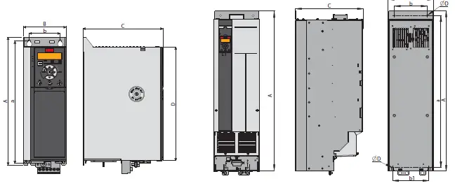
![]()
| Height A [mm (in)] | 210
(8.3) |
272.5
(10.7) |
272.5
(10.7) |
317.5
(12.5) |
410
(16.1) |
515
(20.3) |
550
(21.7) |
889
(35.0) |
1096
(43.1) |
| Height A 1]
[mm (in)] |
– | – | – | – | – | – | – | 909
(35.8) |
1122
(44.2) |
| Width B [mm (in)] | 75
(3.0) |
90
(3.5) |
115
(4.5) |
133
(5.2) |
150
(5.9) |
233
(9.2) |
308
(12.1) |
250
(9.8) |
350
(13.8) |
| Depth C [mm (in)] | 168
(6.6) |
168
(6.6) |
168
(6.6) |
245
(9.6) |
245
(9.6) |
241
(9.5) |
323
(12.7) |
375
(14.8) |
375
(14.8) |
| Depth C 2]
[mm (in)] |
173
(6.8) |
173
(6.8) |
173
(6.8) |
250
(9.8) |
250
(9.8) |
241
(9.5) |
323
(12.7) |
– | – |
| D
[mm (in)] |
180
(7.1) |
240
(9.4) |
240
(9.4) |
270
(10.6) |
364.7
(14.4) |
452
(17.8) |
484.5
(19.0) |
– | – |
| Mounting holes | |||||||||
| a [mm (in)] | 198 (7.8) | 260 (10.2) | 260 (10.2) | 297.5 (11.5) | 390 (15.4) | 495 (19.5) | 521 (20.5) | 844 (33.2) | 1051 (41.4) |
| b [mm (in)] | 60 (2.4) | 70 (2.8) | 90 (3.5) | 105 (4.1) | 120 (4.7) | 200 (7.9) | 270 (10.6) | 180 (7.1) | 280 (11.0) |
| b1 [mm (in)] | 200 (7.9) | 271 (10.7) | |||||||
| Mounting screw | M4 | M5 | M5 | M6 | M6 | M8 | M8 | M8 | M8 |
- Note: Including decoupling plate.
- Note: With option B.
Accessories

VLT® Encoder Input MCB 102
A universal option for connection of encoder feedback from either a motor or a process.
Encoder module supports
- Incremental encoders
- SinCos encoders as HIPERFACE®
- SSI encoders
- Power supply for encoders
- RS422 interface
- Connection to all standard 5 V incremental encoders
VLT® Resolver Input MCB 103
Supports resolver feedback for motors.
- Primary Voltage: 2- 8 Vrms
- Primary Frequency:2.0 kHz – 15 kHz
- Primary current max: 50 mA rms
- Secondary input voltage: 4 Vrms
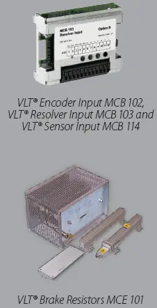
VLT® Sensor Input MCB 114
- Sensor input for temperature transmitters PT100 and PT1000 for monitoring bearing temperatures.
- With one extra current analog input (0/4-20 mA)
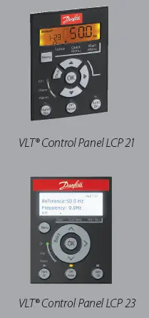
VLT® Control Panel LCP 21
This numerical control panel is an easy user interface for the drive.
- Status messages
- Quick menu for easy commissioning
- Parameter setting and adjusting
- Hand-operated start/stop function or Automatic mode select
- Reset function

VLT® Control Panel LCP 23
A graphic control panel for easy use.
- Easily installed
- Available in English, Chinese, and Portuguese
- Multi-line display
- Support setups and parameter copy
- Reset function
- Cabinet-mounting kit available
VLT® Brake Resistors MCE 101
Energy generated during braking is absorbed by the resistors, protecting electrical components from heating up. Danfoss brake resistors are optimized for the FC series. General versions for horizontal and vertical applications are also available.
- Enclosure protection as IP20 and up to IP65
- Built-in thermo switch
- Versions for vertical and horizontal mounting
- UL recognized – only types for vertical mounting
VLT® 24 V DC Supply MCB 106
VLT® 24 V DC Supply MCB 107
Connect an external DC supply to keep the control section and any installed option functioning during power failure.
This enables full operation of the LCP
(including the parameter setting) and all installed options without connection to mains.
- Input voltage range .……… 24 V DC +/15% (max. 37 V for 10 sec.)
- Max. input current.……………………………….2.2 A
- Max. cable length ……………………………….. 75 m
- Input capacitance load …………………< 10 uF
- Power up delay ..………………………………..< 0.6 s
High dynamic application features
- Integrated motion control features for high dynamic applications
- High performance of speed, positioning, and torque control
- Advanced control algorithm-Flux Basic control with closed loop
- Support various asynchronous and permanent magnet motors
- Mitigating solutions for grid turbulence or power loss situations
- Automatic motor adaption (AMA) to pair the drive and motor automatically
- Embedded application macro features for various applications
- Built-in DC choke to reduce the harmonics distortion
Follow us and learn more about AC drives

AD461136013340en-000302 | © Copyright Danfoss Drives | 2024.07
Any information, including, but not limited to information on selection of product, its application or use, product design, weight, dimensions, capacity or any other technical data in product manuals, catalogues descriptions, advertisements, etc. and whether made available in writing, orally, electronically, online or via download, shall be considered informative, and is only binding if and to the extent, explicit reference is made in a quotation or order confirmation. Danfoss cannot accept any responsibility for possible errors in catalogues, brochures, videos and other material. Danfoss reserves the right to alter its products without notice. This also applies to products ordered but not delivered provided that such alterations can be made without changes to form, fit or function of the product. All trademarks in this material are property of Danfoss A/S or Danfoss group companies. Danfoss and the Danfoss logo are trademarks of Danfoss A/S. All rights reserved.
Documents / Resources
 |
Danfoss FC 360 VLT Automation VFD AC Drives [pdf] User Guide FC 360, FC 360 VLT Automation VFD AC Drives, VLT Automation VFD AC Drives, Automation VFD AC Drives, VFD AC Drives, AC Drives, Drives |


