Danfoss FA11 iC7-Automation In Back Out Back Cooling Kit
Product Information
Specifications
- Product Name: In-back/Out-back Cooling Kit for FA11-FA12 iC7 Series Frequency Converters
- Compatible with: FA11 and FA12 frequency converters mounted in Rittal TS8 cabinets with widths of 600 mm (24 in) or 800 mm (32 in)
- Kit Numbers: 176F4057 (for FA11) and 176F4058 (for FA12)
Product Usage Instructions
Installation
Safety Information
NOTICE: Only qualified, Danfoss authorized personnel are allowed to install the parts described in these installation instructions.
- Disassembly and reassembly of the frequency converter must be done by the service guide.
- Use the standard fastener torque values from the service guide, unless the torque value is specified in these instructions.
WARNING: Discharge Time (40 Minutes)
- Stop the motor.
- Disconnect AC mains and remote DC-link power supplies, including battery back-ups, UPS, and DC-link connections to other frequency converters.
- Wait 40 minutes for the DC-link capacitors to discharge fully.
- Before performing any service or repair work, measure the voltage level to verify that the capacitors are fully discharged.
WARNING: Electrical Shock Hazard
- Only use qualified electricians for the installation.
- Disconnect the frequency converter from all power sources before installation or service.
- Treat the frequency converter as live whenever the mains voltage is connected.
- Follow the guidelines in these instructions and local electrical safety codes.
Items Supplied
The following parts are contained in the kit:
| Item | Description |
|---|---|
| Top cover | Cover for the top of the frequency converter |
| Top gasket | Gasket for sealing the top cover |
| Bottom cover | Cover for the bottom of the frequency converter |
FAQ
- Q: Can I install this cooling kit myself?
A: No, only qualified, Danfoss authorized personnel are allowed to install the parts described in these installation instructions. - Q: How long should I wait for the capacitors to discharge fully?
A: Wait 40 minutes after power has been removed before performing any service or repair work to ensure the capacitors are fully discharged.
Overview
Description
The in-back/out-back cooling kit fits FA11 and FA12 frequency converters mounted in Rittal TS8 cabinets with widths of 600 mm (24 in) or 800 mm (32 in). When the kit is installed, air flows into the lower back duct and out through the upper back duct of the frequency converter. See Illustration 1.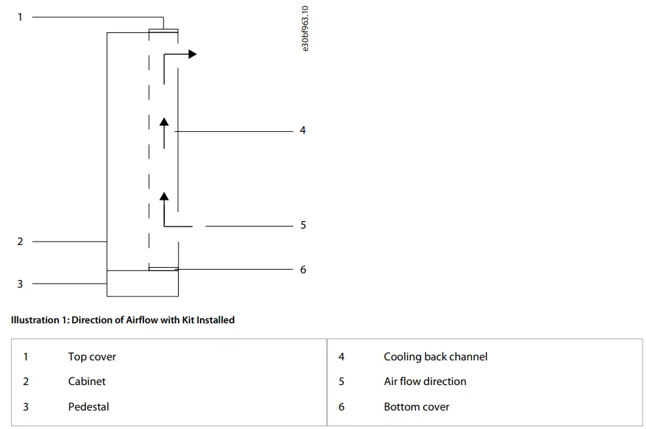
Kit Numbers
Use these instructions with the following kits.
Table 1: In-back/Out-back Cooling Kits
| Number | Kit description |
| 176F4057 | In-back/out-back cooling kit for FA11 frequency converter |
| 176F4058 | In-back/out-back cooling kit for FA12 frequency converter |
Items Supplied
The following parts are contained in the kit.
Table 2: Items Supplied in In-back/Out-back Cooling Kits
| Item | Quantity |
| Top cover | 1 |
| Top gasket | 1 |
| Bottom cover | 1 |
| Bottom gasket | 1 |
| Back duct | 2 |
| 6-hole gasket | 4 |
| 8-hole gasket | 4 |
| Clip-on nut | 16 |
| M5x14 screw | 8–10 |
| M5x18 screw | 16 |
| M6x12 screw | 12 |
Installation
Safety Information
NOTICE – QUALIFIED PERSONNEL
Only qualified, Danfoss authorized personnel are allowed to install the parts described in these installation instructions.
- Disassembly and reassembly of the frequency converter must be done in accordance with the service guide.
- Use the standard fastener torque values from the service guide, unless the torque value is specified in these instructions.
WARNING
- WARNING – DISCHARGE TIME (40 MINUTES)
The frequency converter contains DC-link capacitors, which can remain charged even when the frequency converter is not powered. High voltage can be present even when the warning LED indicator lights are off. Failure to wait 40 minutes after power has been removed before performing service or repair work can result in death or serious injury.- Stop the motor.
- Disconnect AC mains and remote DC-link power supplies, including battery back-ups, UPS, and DC-link connections to other frequency converters.
- Disconnect or lock the motor.
- Disconnect any brake option.
- Disconnect any DC connector option.
- Wait 40 minutes for the DC-link capacitors to discharge fully.
- Before performing any service or repair work, measure the voltage level to verify that the capacitors are fully discharged.
- WARNING – ELECTRICAL SHOCK HAZARD
The frequency converter contains dangerous voltages when connected to mains voltage. Improper installation, and installing or servicing with power connected, can cause death, serious injury, or equipment failure.- Only use qualified electricians for the installation.
- Disconnect the frequency converter from all power sources before installation or service.
- Treat the frequency converter as live whenever the mains voltage is connected.
- Follow the guidelines in these instructions and local electrical safety codes.
- WARNING – ELECTROSTATIC DISCHARGE
Electrostatic discharge can damage components.- Ensure electrostatic discharge before touching internal frequency converter components, for example by touching a grounded, conductive surface or by wearing a grounded armband.
Installation Overview
NOTICE – APPLYING GASKETS
This kit contains self-adhesive gaskets to ensure a proper seal between metal parts. Before affixing a gasket, check that the part matches the gasket and that no holes are covered.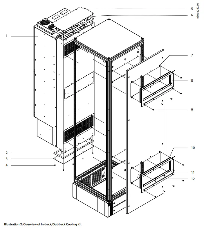

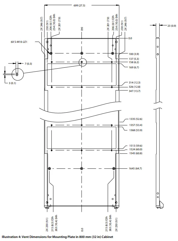
Creating Vent Openings in the Mounting Plate
To create upper and lower vent openings in the mounting plate, use the following steps. Use the dimensions in Illustration 3 for 600 mm (24 in) cabinets, and Illustration 4 for 800 mm (32 in) cabinets.
Procedure
- Drill 6 mounting holes in the back of the frequency converter using the dimensions in the template.
- Insert 6 M10 pem self-clinching nuts (not supplied) in the mounting holes.
- Cut out the upper and lower vent openings in the mounting plate using the dimensions in the template.
The openings must match the frequency converter vent openings. - Drill 6 screw holes around each vent opening using the dimensions in the template.
The holes must match the holes in the frequency converter and the inner flange of the back ducts.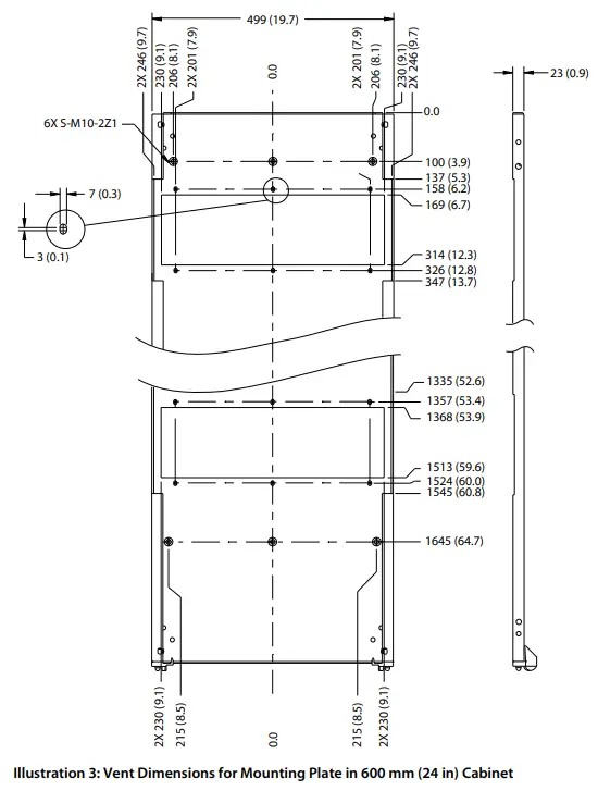
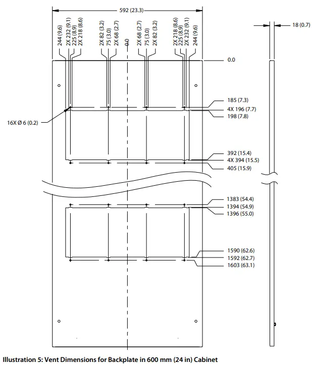
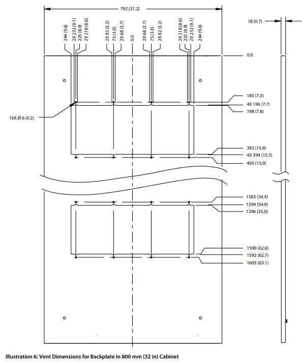
Creating Vent Openings in the Backplate
To create upper and lower vent openings in the cabinet backplate, use the following steps. Use the dimensions in Illustration 5 for 600 mm (24 in) cabinets, and Illustration 6 for 800 mm (32 in) cabinets.
Procedure
- Cut out the vent openings in the cabinet backplate using the dimensions in the template.
The openings must match the frequency converter and mounting plate vent openings. - Drill 8 screw holes (6 mm) around each vent opening using the dimensions in the template.
The holes must match the holes in the frequency converter and in the outer flange of the back duct.
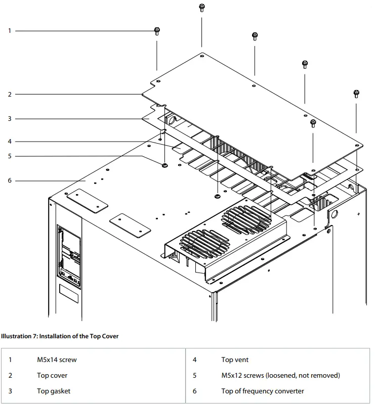
Installing the Top Cover
To install the top cover, use the following steps. See Illustration 7.
Procedure
- Remove paper backing from the top gasket to expose the adhesive.
- Adhere the top gasket to the underside of the top cover.
- Remove the M5x14 screws (T25) surrounding the sides and back of the vent in the top of the frequency converter.
Retain the screws. FA11 converters have 6 screws; FA12 converters have 7 screws. - Loosen 3 M5x12 screws (T25) at the front of the vent in the top surface of the frequency converter.
- Slide the edge of the top cover plate under the 3 loosened screws, positioning the plate over the vent in the top of the frequency converter.
- Secure the top cover plate with the M5x14 screws (T25) removed previously in step 3.
Torque all screws to 2.3 Nm (20 in-lb).
Installing the Bottom Cover
NOTICE- DRAIN OPENING
The bottom cover features a drain opening in the middle of the plate.
- To drain moisture in wet or humid environments, attach nylon tubing with interior diameter of 8 mm (0.3 in).
- To seal the drain in dry environments, fasten a screw in the drain hole.
To install the bottom cover at the lower end of the cooling back channel, use the following steps. See Illustration 8.
Procedure
- Remove the paper backing from the bottom gasket.
- Adhere the gasket to the upper side of the bottom cover.
- Position the bottom cover and gasket over the opening at the lower end of the cooling channel.
- Secure the bottom cover using the M5x14 screws (T25).
Torque screws to 2.3 Nm (20 in-lb). FA11 frequency converters require 8 screws, and FA12 frequency converters require 10 screws.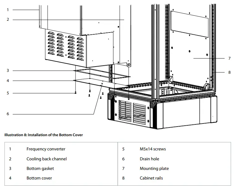
Mounting the Frequency Converter
To install the mounting plate and frequency converter in the cabinet, use the following steps. Refer to Illustration 9.
Procedure
- Remove the paper backing from both 6-hole gaskets, exposing the adhesive.
- Adhere 1 gasket around the vent opening on each side of the mounting plate.
- Position the mounting plate in the Rittal cabinet, aligning the top mounting plate hole with the 5th hole from the top of the cabinet rails.
Check that the pem nuts face the back of the cabinet. - Fasten the mounting plate to the cabinet rails with 14 M5x10 thread-forming screws.
- Loosely fasten 3 M10 screws (not supplied) into the pem nuts at the lower end of the mounting plate.
Check that the screws are secure. The base of the frequency converter rests on the screws. - Slightly lean the top of the frequency converter forward and set the cutouts in the base onto the 3 screws.
- Slowly push the top of the frequency converter back against the mounting plate until the top 3 pem nuts line up with the holes in the frequency converter.
- Secure the top of the frequency converter using 3 M10 screws.
Torque the 6 M10 screws to 19 Nm (170 in-lb).
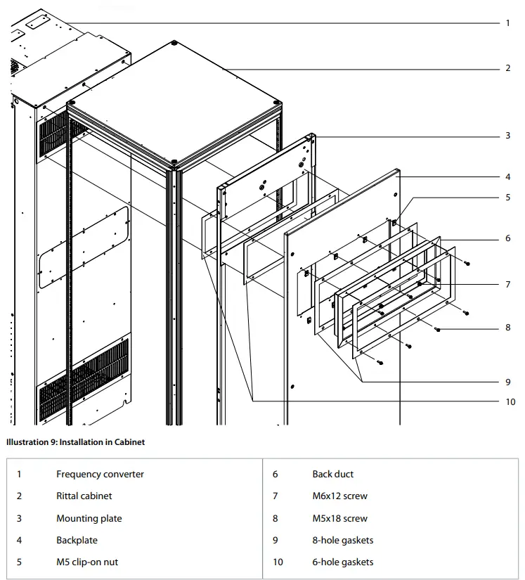
Installing the Backplate and Back Ducts
To attach the cabinet backplate and the upper and lower back ducts, use the following steps.
Procedure
- Position the cabinet backplate on the rear rails of the cabinet behind the mounting plate.
- Secure the backplate to the rails using the existing fasteners.
- Slide 8 M5 clip-on nuts over the screw holes surrounding the upper duct opening in the backplate.
Repeat for the lower duct opening. - Remove the paper backing from 1 pair of 8-hole gaskets, exposing the adhesive.
- Adhere 1 gasket to the back and 1 to the front of the upper back duct outer flange.
Repeat for the lower duct. - Position each back duct in the hole created for it in the mounting plate and cabinet backplate.
- Fasten the inner flanges of the back ducts with 12 M6x12 screws (T30), 6 screws in each duct.
Torque screws to 3.9 Nm (35 in-lb). - Fasten the outer flanges of the back ducts with 16 M5x18 screws (T25), 8 screws in each duct.
Torque screws to 2.3 Nm (20 in-lb).
Danfoss A/S
Ulsnaes 1
DK-6300 Graasten
danfossdrives.com
Any information, including, but not limited to information on selection of product, its application or use, product design, weight, dimensions, capacity or any other technical data in product manuals, catalogues descriptions, advertisements, etc. and whether made available in writing, orally, electronically, online or via download, shall be considered informative, and is only binding if and to the extent, explicit reference is made in a quotation or order confirmation. Danfoss cannot accept any responsibility for possible errors in catalogues, brochures, videos and other material. Danfoss reserves the right to alter its products without notice. This also applies to products ordered but not delivered provided that such alterations can be made without changes to form, fit or function of the product.
All trademarks in this material are property of Danfoss A/S or Danfoss group companies. Danfoss and the Danfoss logo are trademarks of Danfoss A/S. All rights reserved.
Documents / Resources
 |
Danfoss FA11 iC7-Automation In Back Out Back Cooling Kit [pdf] Installation Guide FA11 iC7-Automation In Back Out Back Cooling Kit, FA11, iC7-Automation In Back Out Back Cooling Kit, Out Back Cooling Kit, Cooling Kit |