Danfoss AVQM Flow Controller Installation
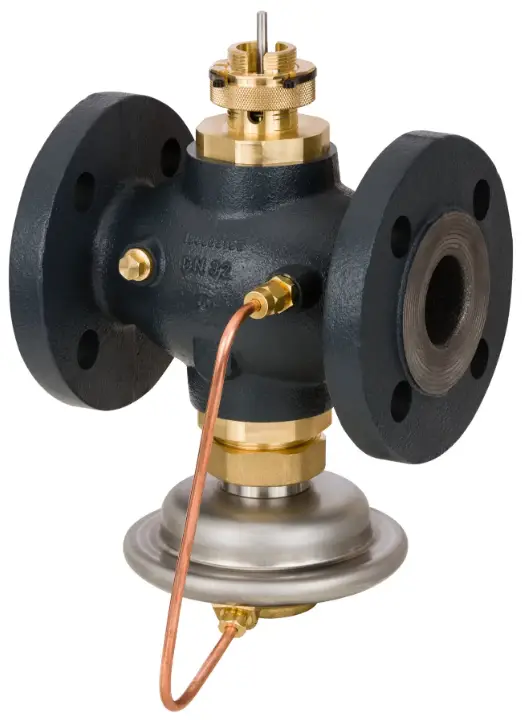
Flow and temperature controller with integrated control valve, WE-version (PN 25)
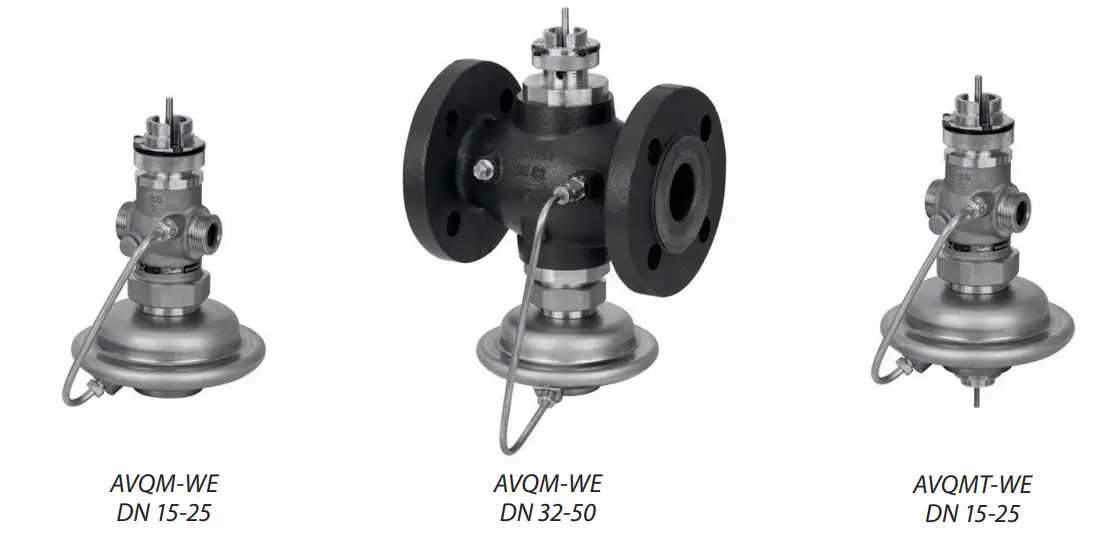
- AVQM-WE – f low controller with integrated control valve
- AVQMT-WE – f low and temperature controller with integrated control valve
Description
- AVQM-WE is a self-acting flow controller with integrated control valve primarily for use in district heating systems. The controller closes when set max. flow is exceeded.
- AVQMT-WE is a self-acting flow and temperature controller with integrated control valve primarily for use in district heating systems. The controller closes on rising temperature or when set max. flow is exceeded. All controllers have special designed (pressure relieved) control valve insert.
- AVQM-WE controller can be combined with Danfoss electrical actuators AMV(E) (and controlled by ECL electronic controllers).
- AVQMT-WE controller can be combined with Danfoss electrical actuators AMV(E) (and controlled by ECL electronic controllers) and with AVT or STM thermostatic actuators.
The controllers have a control valve with adjustable flow restrictor, connection neck for electrical actuator, connection neck for thermostat (AVQMT-WE only), and an actuator with one control diaphragm.
AVQM-WE and AVQMT-WE are used together with Danfoss electrical actuators:
- AMV 150 1)
- AMV(E) 10 1) / AMV(E) 20 / AMV(E) 30
- AMV(E) 13 1) / AMV(E) 23 / AMV(E) 33 with spring return function
- AMV 20 SL / AMV 23 SL / AMV 30 SL with stroke limitation
AMV 150 / AMV(E) 10 / AMV(E) 13 can be combined with DN 15 controller only.
AVQM(T)-WE combined with AMV(E) 13, AMV(E) 23 (SL) or AMV(E) 33 (SL) has been approved according to DIN 32730. The controllers combined with AVT and STM thermostats are type-tested acc. to EN 14597. Controllers combined with STM thermostats protect systems against exceeding temperatures.
Applications:
- District heating systems acc. to DIN 4747
- Heating systems acc. to EN 12828 (DIN 4751) and EN 12953-6 (DIN 4752)
- Water heating systems for drinking and industrial waters acc. to DIN 4753
Main data:
- DN 15-50
- kVS 2.5-25 m3/h
- PN 25
- Setting ranges:
- AVT thermostat:
- 10 … 40 °C / 20 … 70 °C / 40 … 90 °C / 60 … 110 °C and 10 … 45 °C / 35 … 70 °C / 60 … 100 °C / 85 … 125 °C
- STM monitor 20 … 75 °C / 40 … 95 °C / 30 … 110 °C
- Flow restrictor ∆p: 0.2 bar
- Temperature:
- Circulation water / glycolic water up to 30%: 2 … 150 °C
- Connections:
- Ext. thread (weld-on, thread and flange tailpieces)
- Flange
- Flow and return mounting.
Ordering
Example 1 – AVQM-WE controller:
Flow controller with integrated control valve; DN 15; kVS 2.5; PN 25; flow restrictor ∆p 0.2 bar; Tmax 150 °C; ext. thread
- 1× AVQM-WE DN 15 controller Code No: 003H7080
Option: 1× Weld-on tailpieces Code No: 003H6908
The controller will be delivered completely assembled, inclusive impulse tube between valve and actuator. Electrical actuator AMV(E) must be ordered separately.
Example 2 –
AVT (or STM) / AVQMT-WE controller: Flow and temperature controller with integrated control valve, DN 15; kVS 2.5; PN 25; setting range 40 … 90 °C; flow restrictor ∆p 0.2 bar; Tmax 150 °C; ext. thread
- 1× AVQMT-WE DN 15 controller Code No: 003H7084
- 1× AVT thermostatic actuator, 40 … 90 °C Code No: 065-0598
Option:
- – 1× Weld-on tailpieces
Code No: 003H6908
The controller AVQMT-WE will be delivered completely assembled, inclusive impulse tube between valve and actuator. Thermostatic actuator AVT will be delivered separately. Electrical actuator AMV(E) must be ordered separately. In case of safety temp. monitoring STM should be ordered instead of AVT.
Example 3 –
STM / AVT / AVQMT-WE controller: Flow and temperature controller with safety temperature monitor and integrated control valve, DN 15, kVS 2.5; PN 25; setting range 40 … 90 °C; limit range 30 … 110 °C; flow restrictor ∆p 0.2 bar; Tmax 150 °C; ext. thread
- 1× AVQMT-WE DN 15 controller Code No 0: 03H6787
- 1× AVT thermostatic actuator, 40 … 90 °C Code No 0: 65-0598
- 1× STM monitor, 30 … 110 °C Code No 0: 65-0608
- 1× K2 Combination piece Code No 0: 03H6855
Option: 1× Weld-on tailpieces Code No: 003H6908
The controller AVQMT-WE will be delivered completely assembled, inclusive impulse tube between valve and actuator. Combination piece K2, thermostats AVT and STM will be delivered separately. Electrical actuator AMV(E) must be ordered separately.
AVQM-WE Controller
| Picture | DN (mm) | Kvs (m³/h) | Connection | Code No. |
|---|---|---|---|---|
 |
15 | 2.5 | G ¾ A | 003H7080 |
| 15 | 4.0 | Cylindrical external thread acc. to ISO 228/1 | 003H7081 | |
| 20 | 6.3 | G1 A | 003H7082 | |
| 20 | 8.0 | G 1¼ A | 003H7083 | |
 |
25 / 32 / 40 | 12.5 | 003H7088 | |
| 20 | Flanges PN 25, acc. to EN 1092-2 | 003H7089 | ||
| 50 | 25 | 003H7090 |
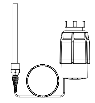
AVQMT-WE Controller
| Picture | DN
(mm) |
kVS
(m3/h) |
Connection | Code No. | |
 |
15 |
2.5 |
Cylindr. ext. thread acc. to ISO 228/1 |
G ¾ A |
003H7084 |
| 4.0 | 003H7085 | ||||
| 20 | 6.3 | G 1 A | 003H7086 | ||
| 25 | 8.0 | G 1¼ A | 003H7087 | ||
AVT Thermostatic actuator
| Picture | For valves | Setting range
(°C) |
Temperature sensor with brass immersion pocket, length, connection | Code No. |
|
|
DN 15-25 |
–10 … +40 |
170 mm, R ½ 1) |
065-0596 |
| 20 … 70 | 065-0597 | |||
| 40 … 90 | 065-0598 | |||
| 60 … 110 | 065-0599 | |||
| 10 … 45 |
255 mm, R ¾ 1) 2) |
065-0604 | ||
| 35 … 70 | 065-0605 | |||
| 60 … 100 | 065-0606 | |||
| 85 … 125 | 065-0607 |
- conic male thread EN 10226-1
- without immersion pocket
STM Safety temperature monitor (actuator)
| Picture | For valves | Limit range
(°C) |
Temperature sensor with brass immersion pocket, length, connection | Code No. |
 |
DN 15-25 |
30 … 110 |
210 mm, R ¾ 1) |
065-0608 |
| 20 … 75 | 065-0609 | |||
| 40 … 95 | 065-0610 | |||
conic male thread EN 10226-1
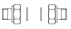
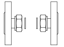
Accessories for valves
| Picture | Type designation | DN | Connection | Code No. | |
|
|
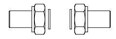
Weld-on tailpieces |
15 |
– |
003H6908 | |
| 20 | 003H6909 | ||||
| 25 | 003H6910 | ||||
|
External thread tailpieces |
15 | Conical ext. thread acc. to
EN 10226-1 |
R ½ | 003H6902 |
| 20 | R ¾ | 003H6903 | |||
| 25 | R 1 | 003H6904 | |||
|
Flange tailpieces |
15 |
Flanges PN 25, acc. to EN 1092-2 |
003H6915 | |
| 20 | 003H6916 | ||||
| 25 | 003H6917 | ||||
Accessories for thermostats
|
Picture |
Type designation |
PN |
For thermostats |
Material |
Code No. |
|
Immersion pocket |
25 |
AVT |
Brass | 065-4414 1) |
| Stainless steel, mat. No. 1.4571 | 065-4415 1) | ||||
|
STM |
Brass | 065-4416 1) | |||
| Stainless steel, mat. No. 1.4435 | 065-4417 1) | ||||
 |
Combination piece K2 |
003H6855 |
|||
Not for AVT thermostatic actuator code numbers: 065-0604, 065-0605, 065-0606, 065-0607
Service kits
For AVQM-WE and AVQMT-WE controlers
Technical data
Valve
| Nominal diameter | DN | 15 | 20 | 25 | 32 | 40 | 50 | |||||
| kVS value of dp controller |
m3/h |
2.5 | 4.0 | 6.3 | 8.0 | 12.5 | 16/201) | 20/251) | ||||
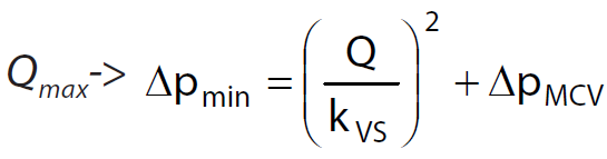
| Range of max.
flow setting |
pMCV = 0.2
bar |
Qmin | 0.07 | 0.07 | 0.16 | 0.2 | 0.4 | 0.8 | 0.8 | |||
| Qmax | 1.6 | 2.4 | 3.5 | 4.5 | 10 | 10.5/121) | 12/141) | |||||
| Avalible p required for Qmax2) | bar | 0.6 | 0.6 | 0.5 | 0.5 | 0.8 | 0.8/0.61) | 0.8/0.61) | ||||
| Stroke | mm | 5 | 7 | 10 | ||||||||
| Control valve authority | 1 (100%) in the range of flow setting | |||||||||||
| Control characteristic | Logarithmic | |||||||||||
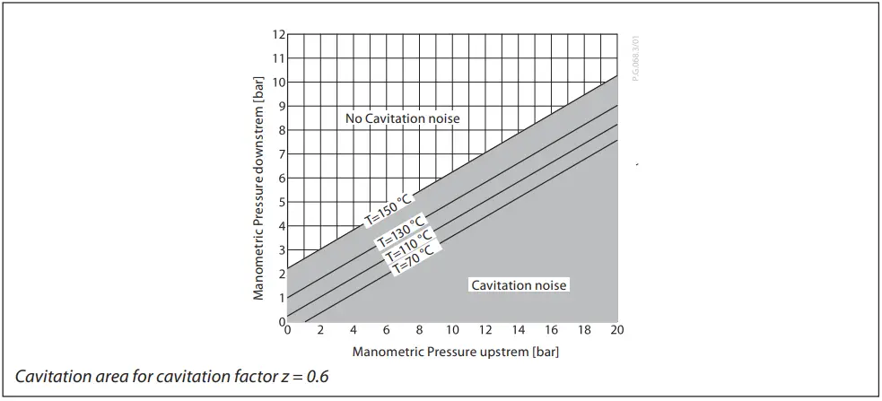
| Cavitation factor z | ≥ 0.6 | ≥ 0.55 | ≥ 0.5 | |||||||||
| Leakage acc. to standard IEC 534 | % of kVS | ≤ 0.02 | ≤ 0.05 | |||||||||
| Nominal pressure | PN | 25 | ||||||||||
| Min. differential pressure |
bar |
see remark 2) | ||||||||||
| Max. differential pressure | 20 | 16 | ||||||||||
| Medium | Circulation water / glycolic water up to 30% | |||||||||||
| Medium pH | Min. 7, max. 10 | |||||||||||
| Medium temperature | oC | 2 … 150 | ||||||||||
|
Connections |
valve | External thread | Flange | |||||||||
| tailpieces | Weld-on, external thread and flange | ⁄ | ||||||||||
| Materials | ||||||||||||
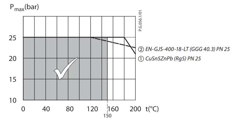
|
Valve body |
Red bronze CuSn5ZnPb (Rg5) |
Ductile iron EN-GJS-400-18-LT
(GGG 40.3) |
||||||||||
| Valve seat | Stainless steel, mat. No. 1.4571 | |||||||||||
| Valve cone | Dezincing free brass CuZn36Pb2As | |||||||||||
| Sealing DP, CV | EPDM | |||||||||||
|
Pressure relieve system |
Control valve insert |
Piston |
||||||||||
| Valve insert | ||||||||||||
Note: DP – diff. pressure controller, MCV – control valve
- Flanged version
- For flows smaller than
Actuator
| Type | AVQM-WE, AVQMT-WE | ||
| Actuator size | cm2 | 54 | |
| Nominal pressure | PN | 25 | |
| Flow restrictor diff. pressure | bar | 0.2 | |
| Materials | |||
| Housing | Upper housing of actuator | Stainless steel, mat. No.1.4301 | |
| Lower housing of actuator | Dezincing free brass CuZn36Pb2As | ||
| Diaphragm | EPDM | ||
| Impulse tube | Copper tube Ø 6 × 1 mm | ||
AVT Thermostatic actuator
| Setting range Xs | °C | −10 … 40 / 20 … 70 / 40 … 90 / 60 … 110
10 … 45 / 35 … 70 / 60 … 100 / 85 … 125 |
|
| Time constant T acc. to EN 14597 | s | max. 50 (170 mm, max. 30 (255 mm) | |
| Gain Ks | mm/°K | 0.2 (170 mm); 0.7 (255 mm) | |
| Max. adm. temperature at sensor | 50 °C above maximum setpoint | ||
| Max. amb. temperature at thermostat | °C | 0 … 70 | |
| Nominal pressure sensor |
PN |
25 |
|
| Nominal pressure immerison pocket | |||
| Capillary tube length | 5 m (170 mm), 4 m (255 mm) | ||
| Materials | |||
| Temperature sensor | Cooper | ||
|
Immersion pocket 1) |
Ms design | Brass, nickel-plated | |
| Stainless steel design | Mat. No. 1.4571 (170 mm) | ||
| Handle for temp. setting | Polyamide, glass fiber-reinforced | ||
| Scale carrier | Polyamide | ||
for sensor 170
STM Safety temperature monitor (actuator)
| Limit range Xs | °C | 20 … 75 / 40 … 95 / 30 … 110 | |
| Time constant T acc. to EN 14597 | s | max. 100 | |
| Gain Ks | mm/°K | 0.3 | |
| Max. adm. temperature at sensor | 80 °C above maximum setpoint | ||
| Max. amb. temperature at thermostat | °C | 0 … 70 | |
| Nominal pressure sensor |
PN |
25 |
|
| Nominal pressure immerison pocket | |||
| Capillary tube length | m | 5 | |
| Materials | |||
| Temperature sensor | Cooper | ||
|
Immersion pocket |
Ms design | Brass, nickel-plated | |
| Stainless steel design | mat. No. 1.4435 | ||
| Handle for temp. setting | Polyamide, glass fiber-reinforced | ||
| Scale carrier | Polyamide | ||
Application principles
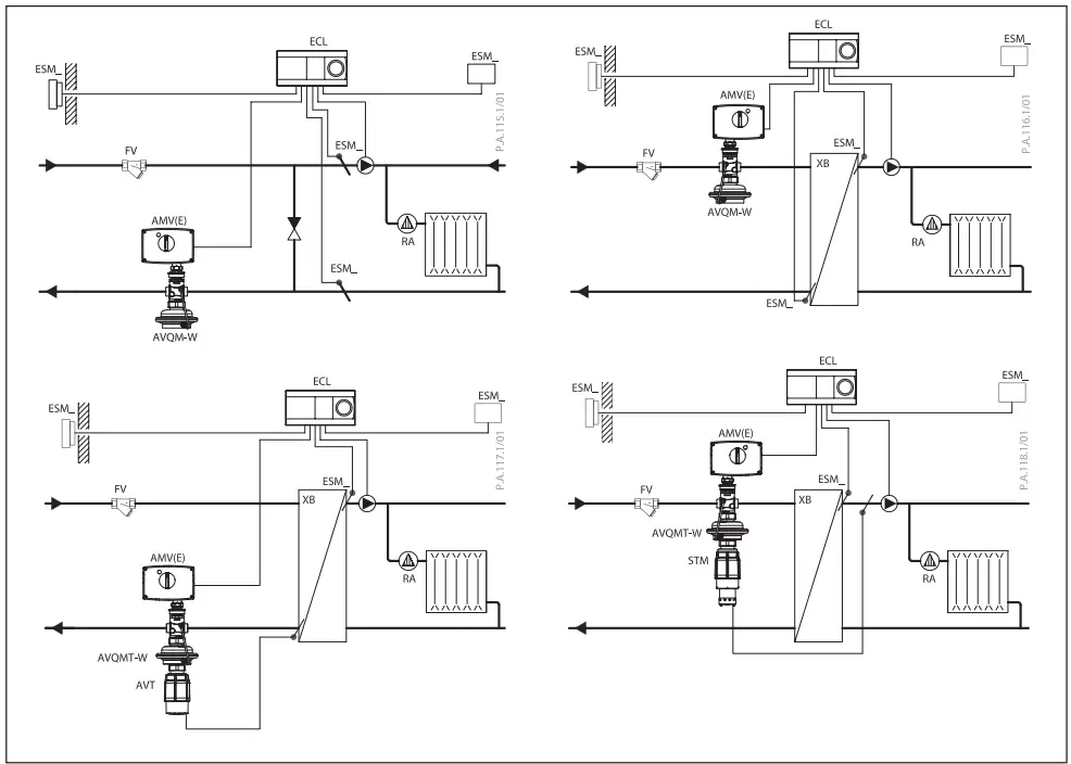
Combinations
- AVQM-WE / AMV(E)
Flow controller with electrical actuator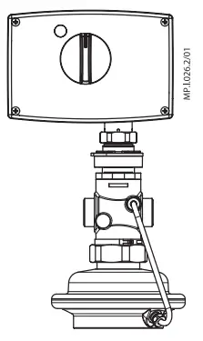
- AVT / AVQMT-WE / AMV(E)
Flow and temperature controller with electrical actuator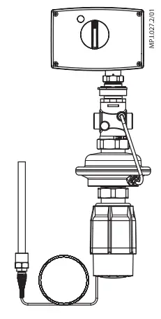
- STM / AVQMT-WE / AMV(E)
Flow controller with safety temperature monitor and electrical actuator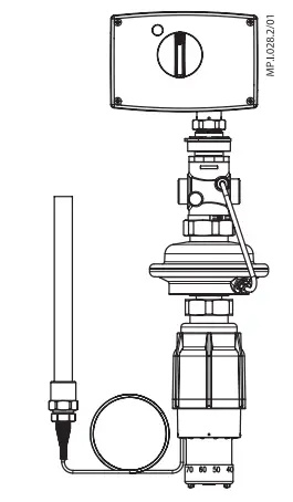
- STM / AVT / AVQMT-WE / AMV(E)
Flow and temperature controller with safety temperature monitor and electrical actuator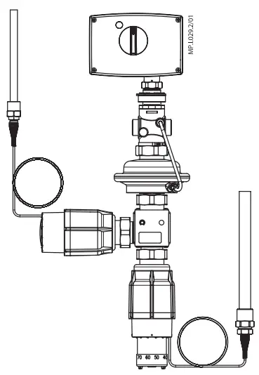
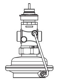
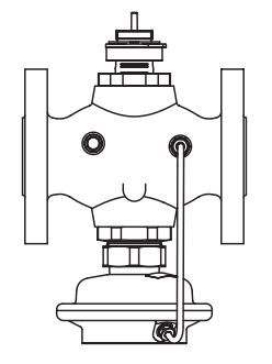
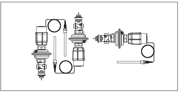
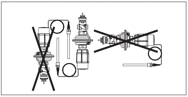
Installation positions
- Flow and temperature controller with integrated control valve (with AVT or STM)
- Up to medium temperature of 100 °C the controllers can be installed in any position.
- For higher temperatures the controllers have to be installed in horizontal pipes only, with a pressure and temperature actuator oriented downwards.
Electrical actuator
Note! Installation positions for electrical actuators AMV(E) have to be observed as well. Please see relevant Data sheet.
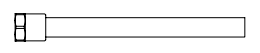
- Temperature sensor
The place of installation must be chosen in a way that the temperature of the medium is directly taken without any delay. Avoid overheating of temperature sensor. The temperature sensor must be immersed into the medium in its full length. - Temperature sensors 170 mm R½
The temperature sensor may be installed in any position.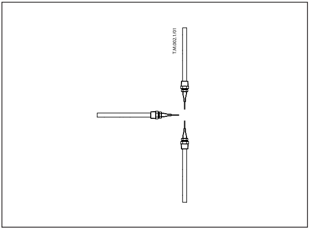
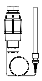
- Temperature sensor 255 mm R¾
The temperature sensor must be installed as shown on the picture.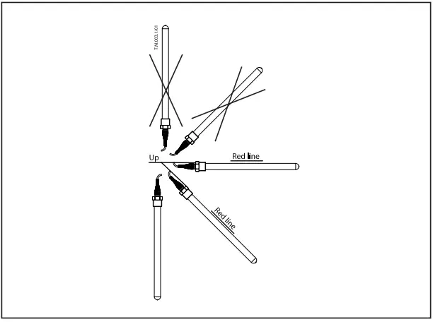
Pressure temperature diagram
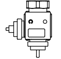
Design
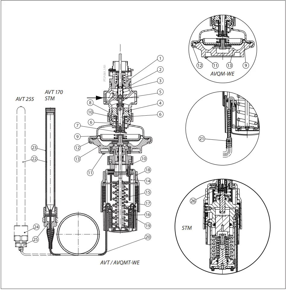
- Control valve insert
- Adjustable flow restrictor
- Valve body
- Valve insert
- Pressure relieved valve cone
- Valve stem
- Built-in spring for flow rate control
- Control drain
- Control diaphragm
- Union nut
- Impulse tube
- Upper casing of diaphragm
- Lower casing of diaphragm
- Thermostat AVT, STM
- Thermostat stem
- Bellows
- Setting spring for temperature control
- Handle for temperature setting, prepared for sealing
- Scale carrier
- Capillary tube
- Flexible protected pipe (at 255mm only)
- Temperature sensor
- Immersion pocket
- Sensor stuffing box
- Housing of sensor stuffing box
- Safety spring
Function
- Flow and temperature controller with integrated control valve (AVQM-WE, AVQMT-WE)
Flow volume causes pressure drop across the adjustable flow restrictor. Resulting pressures are being transferred through the impulse tubes and/or control drain in the actuator stem to the actuator chambers and act on control diaphragm for flow control. The flow restrictor diff. pressure is controlled and limited by means of built-in spring for flow control. Control valve closes on rising differential pressure and opens on falling differential pressure to control max flow. Additionally the electrical actuator will operate from zero to set max. flow according to the load. - Safety Temperature Monitor (STM): Function
The safety temperature monitor is proportional temperature controller which controls temperature and protects the system against exceeding temperatures. The valve cone is soft sealed and pressure relieved. In case the temperature at the temperature sensor exceeds the adjusted set point, safety temperature monitor interrupts energy supply by closing the valve. As soon as the temperature at the temperature sensor drops, the valve opens automatically. Handle for limit setting can be sealed. - Extended safety function
If there is a leakage in the area of the temperature sensor, the capillary tube, or the thermostat, the valve closes by a safety spring in the safety thermostat. In this case safety temperature monitor (actuator) must be replaced. - Physical Function Principle
The safety temperature monitor operates in accordance with the liquid expansionprinciple. The temperature sensor, the capillary tube and the bellows are filled with liquid. As the temperature at the temperature sensor rises, the liquid expands, the thermostat stem moves out and closes the valve. - Temperature Controller (AVT): Function
By increasing of medium temperature control valve cone moves towards the seat (valve closes), by decreasing of medium temperature valve cone moves away from the seat (valve opens). Handle for temperature setting can be sealed. - Physical Function Principle
Medium temperature changes cause pressure changes in temperature sensor. Resulting pressure is being transferred through the capillary tube to the bellows. Bellows moves thermostat stem and opens or closes the valve.
Settings
- Flow setting
Flow setting is being done by the adjustment of the flow restrictor position. The adjustment can be performed on the basis of flow adjustment diagram (see relevant instructions) and/or by the means of heat meter. - Temperature setting (AVT)
Temperature setting is being done by the adjustment of the setting spring for temperature control. The adjustment can be done by means of handle for temperature setting and/or temperature indicators. - Limit setting (STM)
Limit setting is being done by the adjustment of the setting spring for temperature control. The adjustment can be done by means of handle for limit setting and/or temperature indicators.
Adjustment diagram
Temperature setting
Relation between scale numbers 1-5 and closing temperature.
Note: The values given are approximate
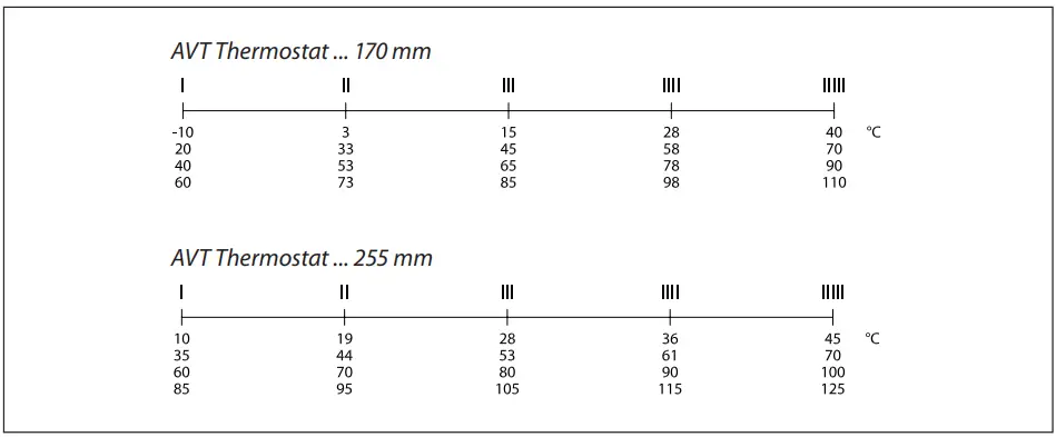
Note: STM Safety temperature monitor (actuator): temperature scale is already written on the product
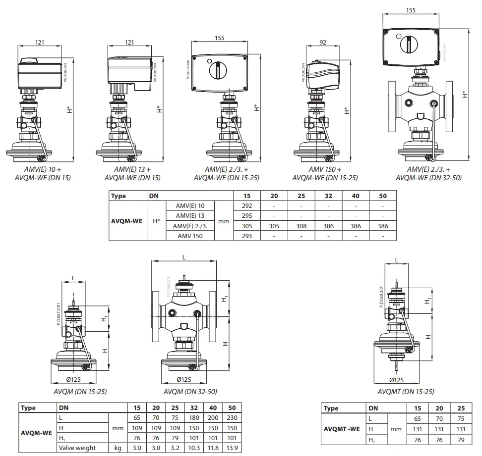
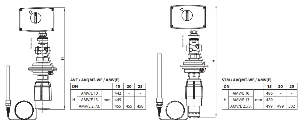
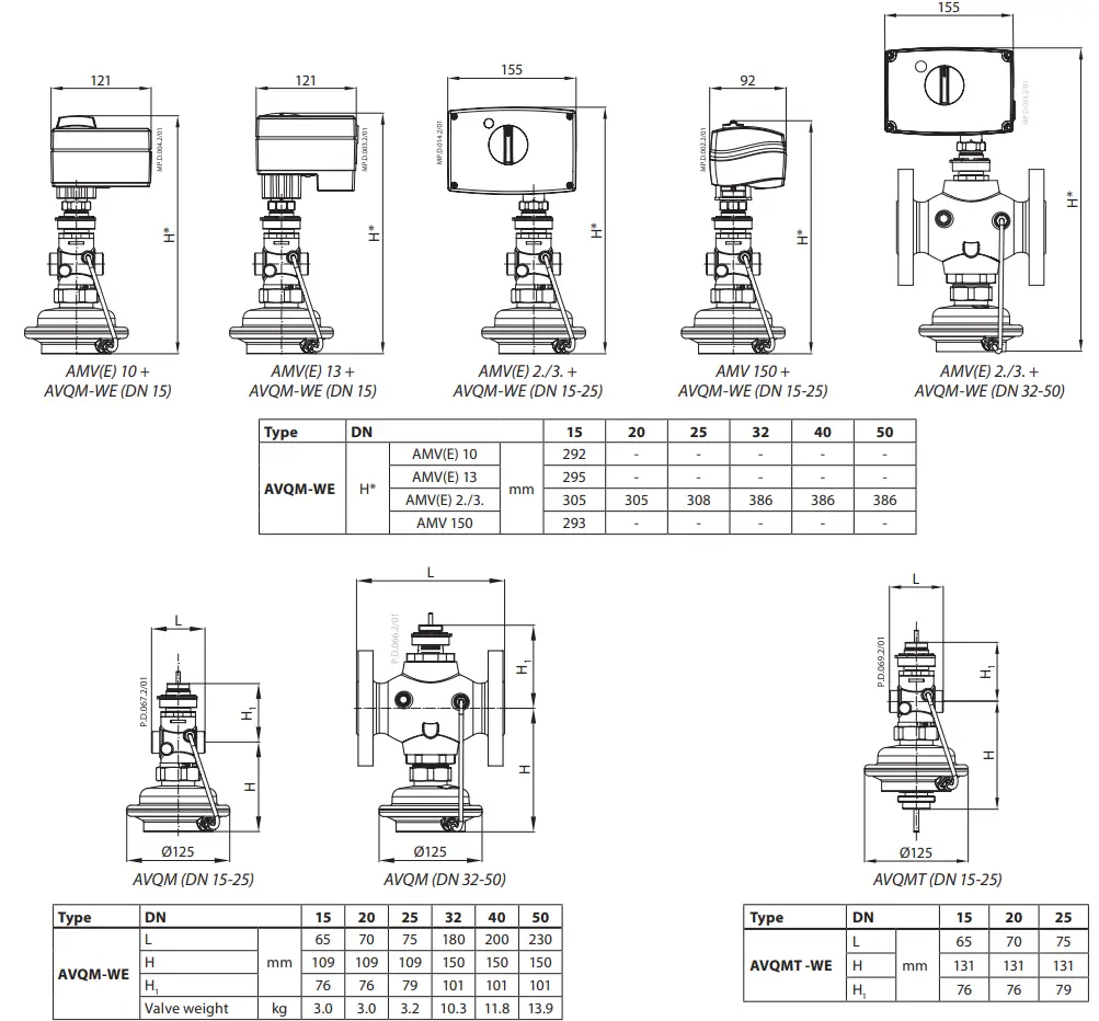
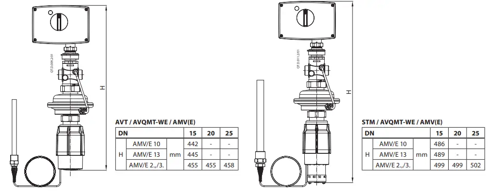
Dimensions
Adjustment diagram
Temperature setting
Relation between scale numbers 1-5 and closing temperature.
Note: The values given are approximate
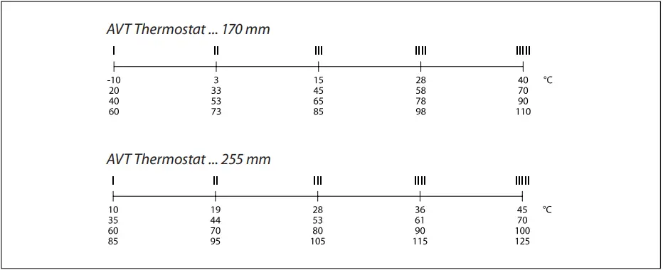
Note: STM Safety temperature monitor (actuator): temperature scale is already written on the product
Danfoss A/S
- Climate Solutions
- climatesolutions.danfoss.com
- +45 7488 2222
- E-Mail: climatesolutions@danfoss.com
Any information, including, but not limited to information on selection of product, its application or use, product design, weight, dimensions, capacity or any other technical data in product manuals catalogues descriptions, advertisements, etc. and whether made available in writing, orally, electronically, online or via download, shall be considered informative, and is only binding if and to the extent, explicit reference is made in a quotation or order confirmation. Danfoss cannot accept any responsibility for possible errors in catalogues, brochures, videos and other material. Danfoss reserves the right to alter its products without notice. This also applies to products ordered but not delivered provided that such alterations can be made without changes to form, fit or function of the product. All trademarks in this material are property of Danfoss A/S or Danfoss group companies. Danfoss and the Danfoss logo are trademarks of Danfoss A/S. All rights reserved.
Documents / Resources
 |
Danfoss AVQM Flow Controller [pdf] Installation Guide 003R9131, 7369170-2, VI.56.I2.00, AVQM Flow Controller, AVQM, Flow Controller, Controller |