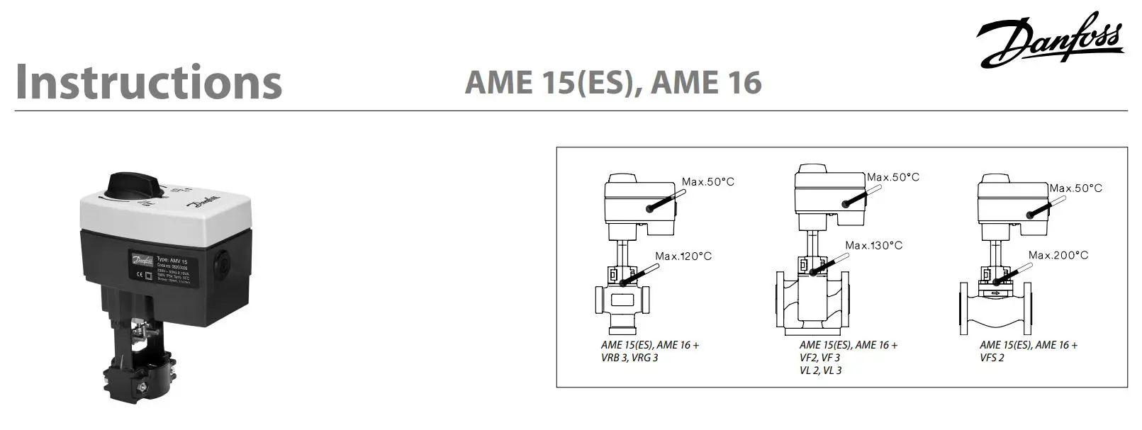
Danfoss AME 15(ES),AME 16 Actuators For
Modulating Control Instructions
Safety Note
To avoid injury of persons and damages to the device, it is absolutely necessary to read and observe these instructions carefully.
Necessary assembly, start-up, and maintenance work must be performed by qualified and authorized personnel only.
Prior to assembly and depressurizing the system.
Please comply with the instructions of the system manufacturer or system operator.
![]()
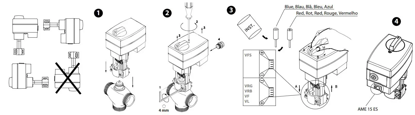
Mounting
Fix the AME 15(ES), AME 16 on the valve.
Note: External ON/OFF switch (fig.4) – only for AME 15 ES AME 15 ES has external switch which can be used for disconnecting actuator from powe supply. By using the switch the actuator is disconnected from power supply (SP is disconnected).
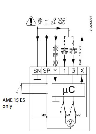
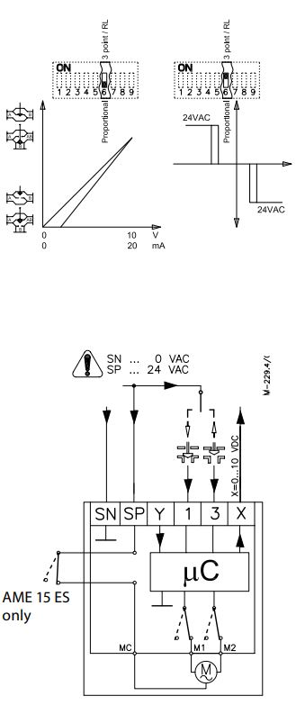
Wiring
Control signal
Control signal from the controller must be connected to terminals Y (input signal) and SN (common) on the AME printed board.
Output signal
Output signal from the terminal X can be used for indication of the current position. Range depends on the DIP switch settings.
Supply voltage
Supply voltage (24V~ -15 to +10%, 50 Hz) must be connected to the terminals SN and SP.
DIP switch settings
Factory settings: ALL switches are on OFF position!
NOTE: All combinations of DIP switches are allowed. All functions that are selected are added consecutively. There is only one logic override of functionalities i.e. the switch No.6 Proportional / 3 point, which sets actuator to ignore control signal and works as a “simple” 3-point actuator.
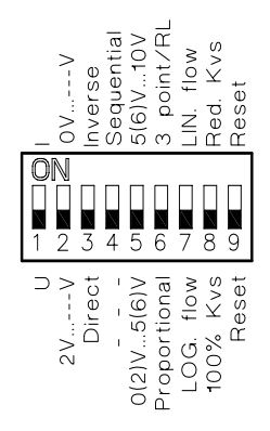
U/I
Actuator can responded to a voltage or current control signal. With switch No.1: U/I actuator can be set either to operate with a voltage control signal (actuator responds to signal between 0…10V), or current control signal (actuator responds to signal between 0…20mA).
Factory setting: voltage control signal (0 … 10 V).
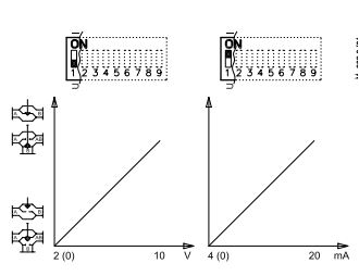
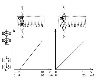
2V…10 / 0V…10
Actuator can be set to response on a control signal from 2V, or 0V. If the actuator is set to current signal than it responds to control signal from 4mA or 0mA.
Factory setting is: 2 … 10V.
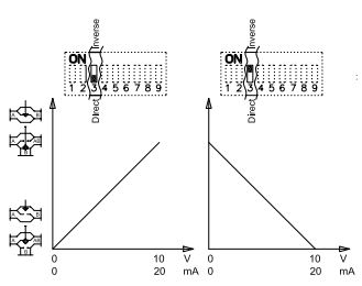
Direct/Inverse
Actuator can be set for spindle to travel downwards on rising control signal (DIRECT), OR for spindle to travel upwards on rising control signal (INVERSE)
Factory setting is: DIRECT
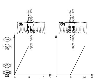
—/Sequential
Two actuators can be set to work parallel with one control signal. If the SEQUENTIAL is set than an actuator responds to split control signal (see 0(2)V…5(6V) / 6(6)V…10V).
NOTE: This combination works in combination with switch No.5: 0(2)V…5(6V) / 6(6)V…10V
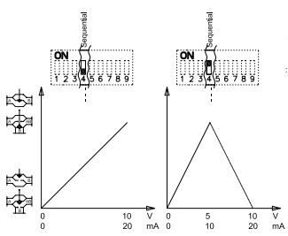
0(2)V…5(6V)/6(6)V…10V
NOTE: This function is available if switch No.4: — / Sequential is set. Actuator can be set to match the range of the control signal: 2…6 V
(switch No.2: 2 V…10) 0…5 V
(switch No.2: 0 V…10) 4…12 mA
(switch No.2: 2 V…10) 0…10 mA
(switch No.2: 0…10)
OR
6…10 V (switch No.2: 2 V…10)
5…10 V (switch No.2: 0 V…10)
12…20 mA (switch No.2: 2 V…10)
10…20 mA (switch No.2: 0…10)
Proportional/3 point
Actuator can operate as “simple” 3-point actuator, if the 3-point function is selected. Power supply should be connected on SN and SP ports. On port 1 or 3 24VAC signal is connected for rising or lowering of actuator. Return signal X indicates the correct position.
NOTE:
if 3 point function is selected actuator does not respond to any control signal on port Y. It only rises and lowers spindle if power is supplied on port 1 or 3.
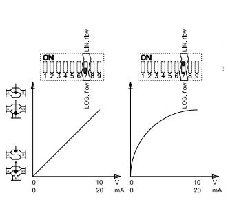
LOG. flow/LIN. flow
Almost all Danfoss valves that fit the actuator have logarithmic (equal percentage) flow/position characteristic. With setting switch to LIN. flow the characteristic of motorised valve can be affected. Combination of actuator and valve can work together as valve with LINEAR characteristic.
Factory setting: LOG. Flow (characteristic of valve is unchanged)
NOTE: If this function is used in combination with non-logarithmic valves the characteristic of motorised valve will be anti-logarithm of valve’s characteristic (e.g. valve with linear characteristic will be transformed to quick open characteristic).
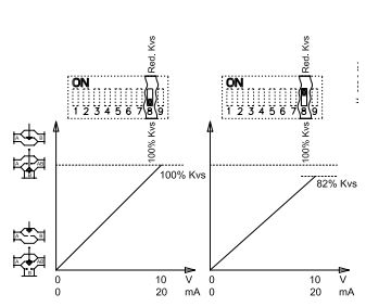
100% KVS/RED. KVS
Actuator can be set to reduce KVS value of a valve. With setting RED. KVS the maximal flow through the valve is reduced for half increment toward the next smaller standard KVS value with logarithmic characteristic (e.g: standard valve with KVS 16 and function RED. KVS causes that motorised valve to work as the valve with KVS13 (half-way between KVS10 and KVS16).
NOTE:
This function works proper only with logarithmic (equal percentage) valves.
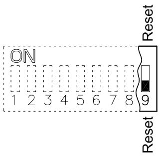
Reset
After the actuator has been connected to power supply, the actuator will start the self-adjustment procedure. The indicator LED flashes until self adjustment is finished. The duration depends on the spindle travel and will normally last a few minutes. The stroke length of the valve is stored in the memory after self adjustment has been completed. To restart self adjustment, change the position of RESET switch (switch No.9). If the supply voltage is switched off or falls below 80% in more than 0.1s, the current valve position will be stored in the memory and all data remain saved in the memory also after a power supply cut-out.
Function test
The indicator light shows whether the positioner is in operation or not. Moreover, the indicator shows the control status and faults. Constant light
– normal operation No light
– no operation or no power supply Intermittent light (1 Hz)
– self adjusting-mode Intermittent light (3 Hz):
– power supply too low
– insufficient valve stroke (<20 s)
– end-position cannot be reached.
Documents / Resources
 |
Danfoss AME 15(ES),AME 16 Actuators For Modulating Control [pdf] Instructions 15 ES, 16, AME 15 ES AME 16 Actuators For Modulating Control, AME 15 ES AME 16, Actuators For Modulating Control, For Modulating Control, Modulating Control |