Danfoss AME 140X Actuators for Modulating Control
Safety Notes
- To avoid injury of persons and damages to the device, it is absolutely necessary to read and observe these instructions carefully.
- Necessary assembly, start-up, and maintenance work must be performed by qualified and authorized personnel only.
- Please comply with the instructions of the system manufacturer or system operator.
- Do not remove the cover before the power supply is fully switched off.
AC 24 V
Connect via safety isolating transformer.
Disposal instruction
- This product should be dismantled and its components sorted, if possible, in various groups before recycling or disposal.
- Always follow the local disposal regulations.
Mounting 1
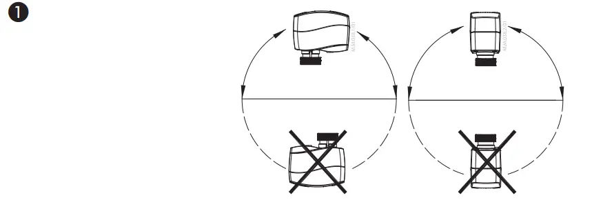
The actuator should be mounted with the valve stem in either horizontal position or pointing upwards.
Installation 2
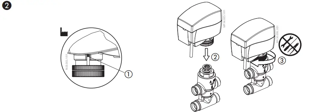 Check the valve neck.
- The actuator should be in steam up position (factory setting) ①.
- Ensure that the actuator is mounted securely on the valve body ②, ③.
The actuator is fixed to the valve body by means of a ribbed nut which requires no tools for mounting. The ribbed nut should be tightened by hand. - Wire the actuator according to the wiring diagram ❸.
- The direction of stem movement can be observed on the position indicator ①.
Auto sleep mode
- If actuator is not mounted to the valve but connected to the power supply, it will first run to its extracted end position (buzz noise from the motor will appear). This behavior will last for max 3 minutes when power supply will be automatically cut off from electro motor and LED indicators.
- It is mandatory to drive the spindle of the actuator to upper position before it will be installed on valve (please refer to manual override drawings)!
- Auto sleep mode switches back to learning mode by pressing RESET button or by cycling power supply.
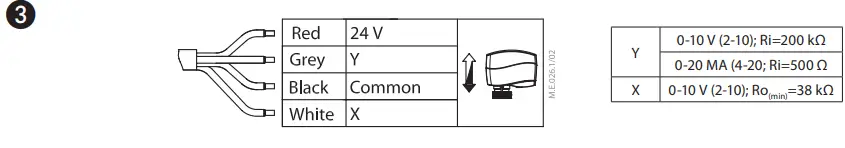
Wiring 3
 Do not touch anything on the PCB!Switch off the power line before wire the actuator! Lethal voltage!
Wire the actuator according to the wiring diagram.
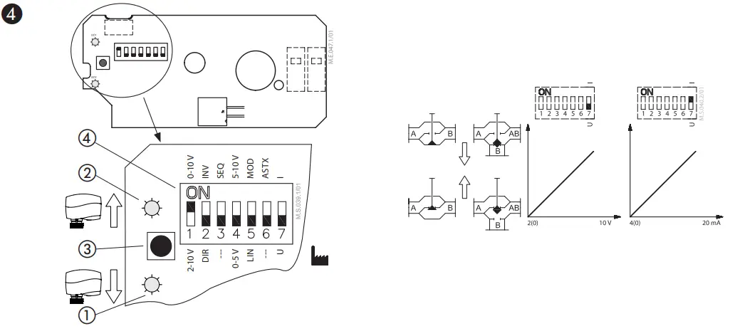
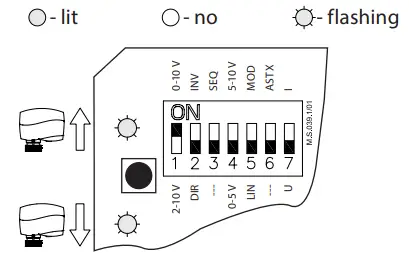
DIP switch settings 4
 Factory settings:
ALL switches (except SW 1 which is in ON position) are in OFF position! ④
NOTE:
All combinations of DIP switches are allowed. All functions that are selected are added consecutively.
- SW 1: 0/2 – Input signal range selector
- If set to OFF position, the input signal is in
- the range from 2-10 V (voltage input) or from 4-20 mA (current input).
- If set to ON position, the input signal is in the range from 0-10 V (voltage input) or from 0-20 mA (current input).
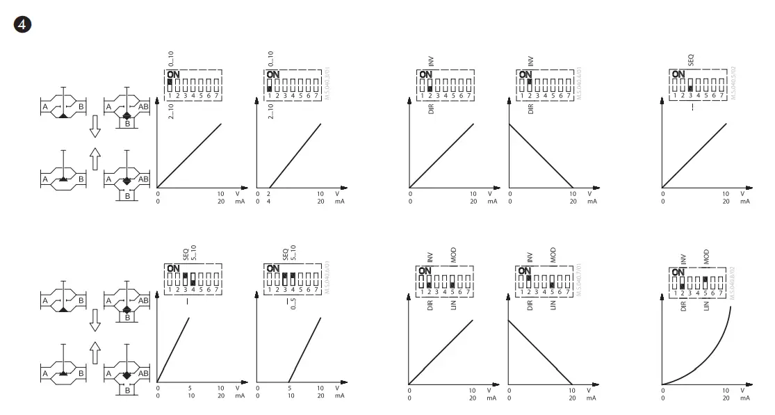
- SW 2 : D/I – Direct or inverse acting selector If set to OFF position, the actuator is direct acting (stem lowers as voltage increases).
- If the actuator is set to ON position, the actuator is inverse acting (stem raises as voltage increases).
- SW 3: —/Seq – Normal or sequential mode selector
- If set to OFF position, the actuator is working in range 0(2)-10 V or 0(4)-20 mA.
- If set to ON position, the actuator is working in sequential range; 0(2)-5(6) V or (0(4)-10(12)mA) or (5(6)-10 V) or (10(12)-20 mA).
- SW 4: 0-5 V/5-10 V – Input signal range in sequential mode
- If set to OFF position, the actuator is working in sequential range 0(2)-5(6) V or 0(4)-10(12) mA.
- If set to ON position, the actuator is working in sequential range; 5(6)-10 V or 10(12)-20 mA.
- SW 5: LIN/MOD – Linear or modified flow through the VZL valves
If set to ON position, the flow through the LINEAR characterized VZL valve will modify to equal percentage-wise equals the control signal.
If set to OFF position, the flow through the valve VZ or VZL remains same as is valve characteristic in accordance to the control signal. - SW 6: —/ASTK – Anti-blocking function Exercises the valve to avoid blocking in periods when the heating/cooling is off.
If set to ON position (ASTK), the valve motion is switched on. The actuator opens and closes the valve every 7 days.
If set to OFF position (—), the function is disabled. - SW 7: U/I – Input signal type selector
If set to OFF position, voltage input is selected.
If set to ON position, current input is selected
Reset button ❹③
Press the reset button will cause the actuator to go through a self stroking cycle (press it for 2 s).
Manual override 5
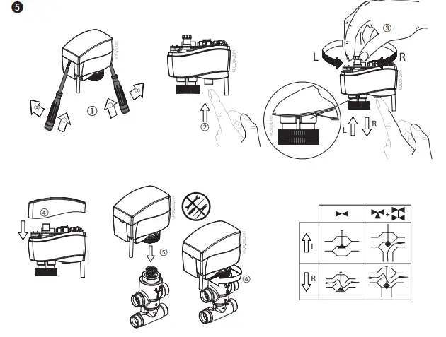
- Do not manually operate the drive if power is connected!
- Do not dismount the actuator
Remove cover ①
Press and hold the button (on the bottom side of the actuator) ② during manual override ③
Replace cover ④
Install actuator on valve ⑤, ⑥
Remark:
A ‘click’ sound after energising the actuator indicates that the gear wheel has jumped into normal position.
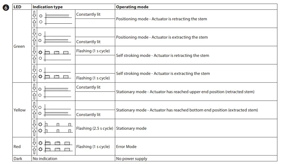
LED signalisation 6
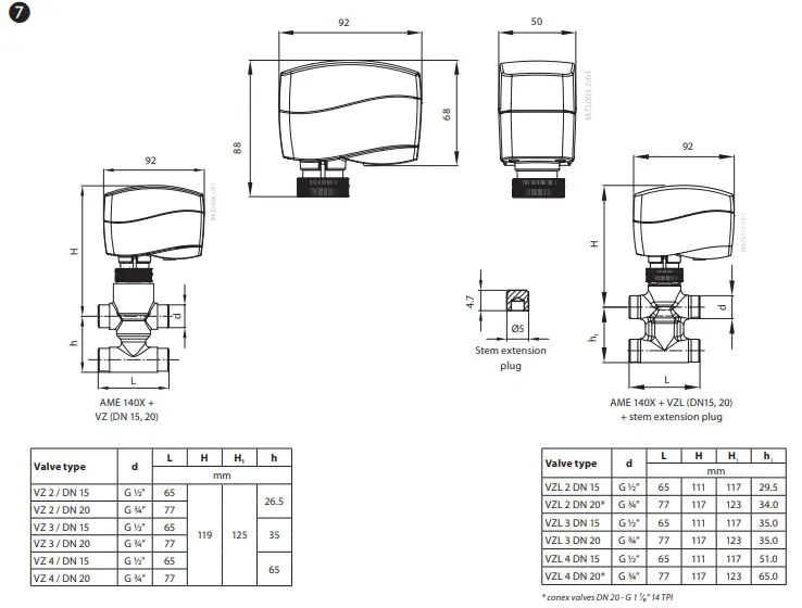
Dimensions 7
Hazardous Substances Table
| Part Name | Hazardous Substances Table | |||||
| Lead (Pb) | Mercury (Hg) | Cadmium (Cd) | Hexavalent Chromium (Cr(VI)) | Polybrominated biphenyls (PBB) | Polybrominated diphenyl ethers (PBDE) | |
| Connecting nut/ | X | O | O | O | O | O |
| O: Indicates that this hazardous substance contained in all of the homogeneous material for this part is below the limit requirement in GB/T 26572; | ||||||
| X: Indicates that this hazardous substance contained in at least one of the homogeneous material for this part is above the limit requirement in GB/T 26572; | ||||||
Danfoss can accept no responsibility for possible errors in catalogues, brochures and other printed material. Danfoss reserves the right to alter its products without notice. This also applies to products already on order provided that such alterations can be made without subsequential changes being necessary eady agreed.
All trademarks in this material are property of the respective companies. Danfoss and the Danfoss logotype are trademarks of Danfoss A/S. All rights reserved.
Documents / Resources
 |
Danfoss AME 140X Actuators for Modulating Control [pdf] User Guide AME 140X, VZ 2, VZL 2, VZ 3, VZL 3, VZ 4, VZL 4, AME 140X Actuators for Modulating Control, AME 140X, Actuators for Modulating Control, Modulating Control |