Danfoss AMB 162 Actuator For Temperature Control In Central Heating Systems
Product Usage Instructions
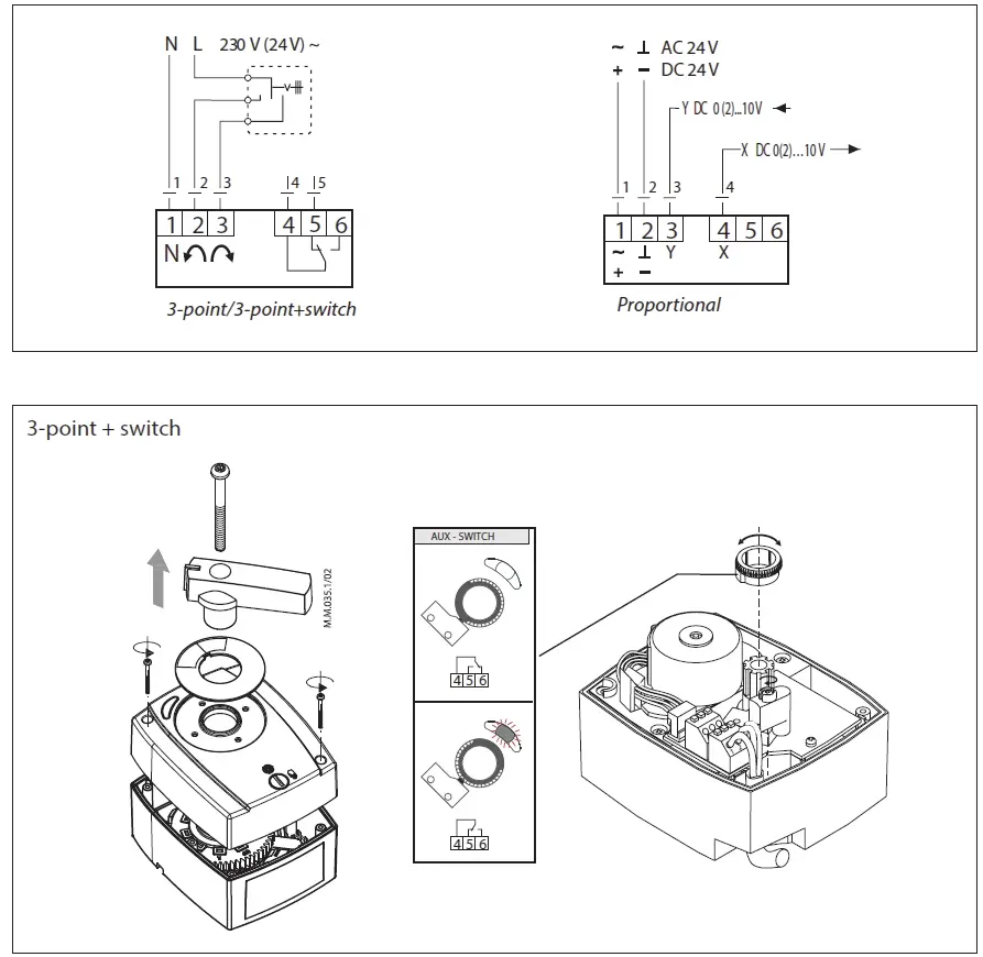
- Power Supply Connection
- Connect the power supply wires according to the specified N L 230 V (24V) ~ configuration.
- Input and Output Connections
- Connect the AC 24 V and DC 24 V input voltages to the corresponding terminals. Connect the output voltage Y DC and control signal X DC to the designated terminals.
- Operating Mode Selection
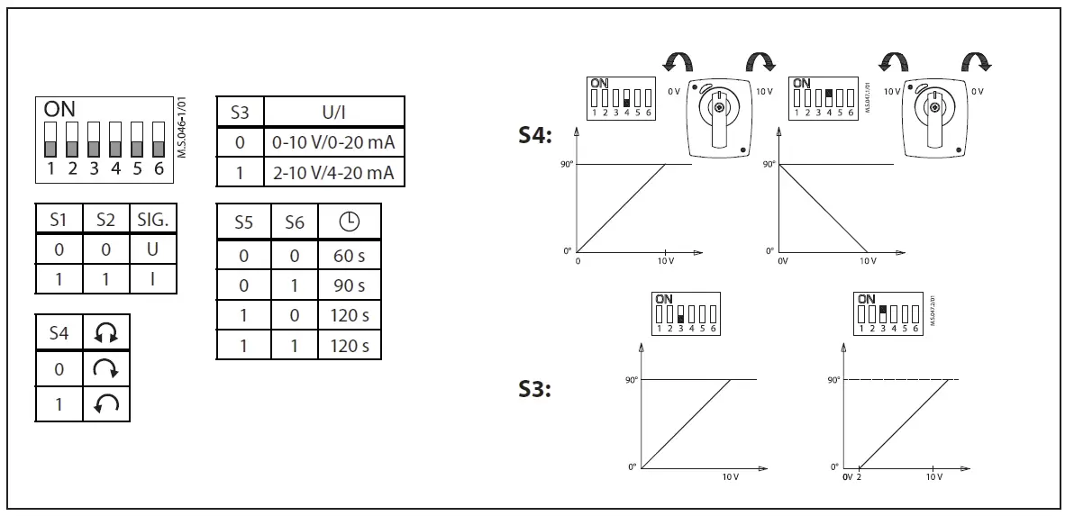
- Set the operating mode to either 3-point or 3-point+switch, Modulating as per your requirements.
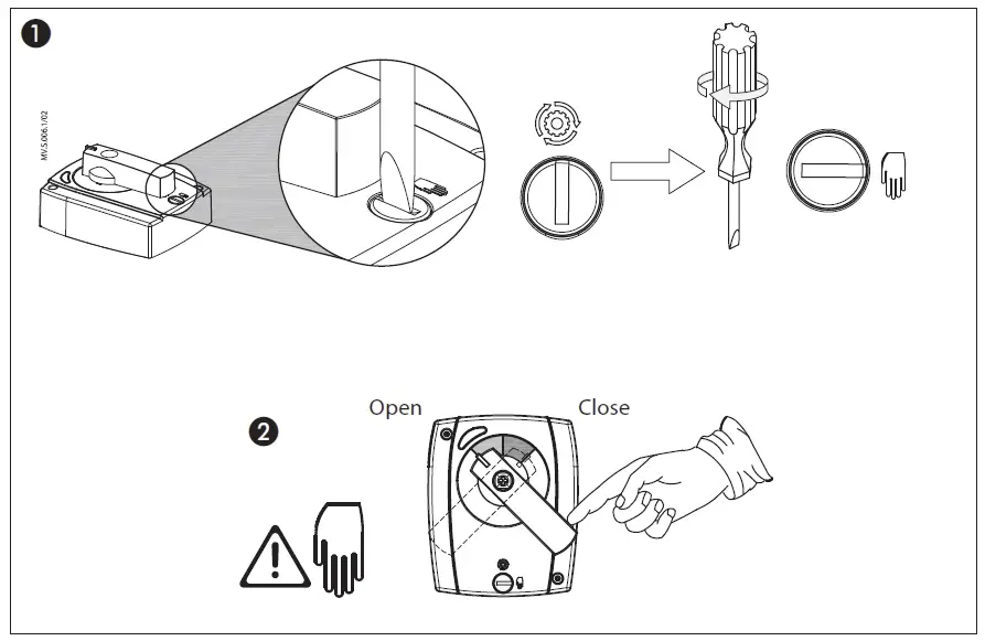
- Valve Control
- Use the S4 switch for valve control. Rotate the switch to open or close the valve. The LED indicators will show the status of the valve.
Description
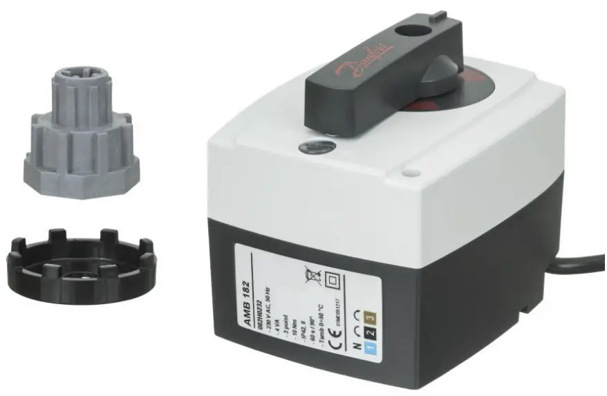
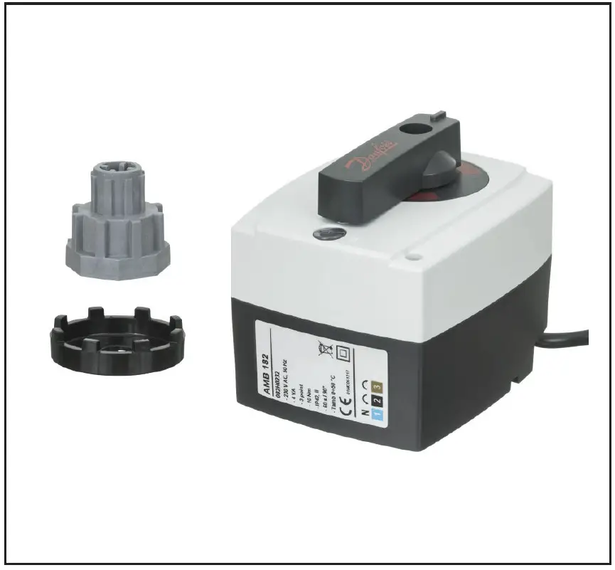 Actuators AMB are intended to control rotating mixing and diverting valves. AMB 162 and AMB 182 actuators are used for temperature control in central heating systems together with 3-way and 4-way rotary valves of the types HRB, HRE and HFE.
Features
- Additional AUXILIARY switch;
- Indication of actual valve position;
- LED indication of turning direction;
- Manual valve turning mode is enabled by a permanent clutch.
- No damage in case of valve blocking.
- Silent and reliable operation;
- Maintenance-free;
- Selectable speed on DIP switch;
- LED indication of activated AUXILIARY switch ( 3-point controlled actuators only).
Main Data:
- Nominal voltage:
- 230 V AC, 50/60 Hz,
- 24 V AC, 50/60 Hz – 3-point,
- 24V AC/DC – modulating;
- Output torque 5, 10, and 15 Nm;
- Rotation angle 90°;
- Actuator running speed
- variants: 15/30/60/120/240/480 sec. per 90°(option to change speeds on DIP switch);
- Control signal:
- 3-point,
- modulating (0(2)-10 V).
Ordering
| Type | Torque | Control signal | Speed | Supply voltage | Remark | For RVA DN | Code No. |
| (Nm) | (s/90°) | (V) | |||||
|
AMB 162 |
5 |
3-point |
15 |
24 |
– |
15-50 |
082H0210 |
| 30 | 082H0211 | ||||||
| 60 | 082H0212 | ||||||
| 120 | 082H0213 | ||||||
| 480 | 082H0214 | ||||||
| 15 |
AS* |
082H0215 | |||||
| 30 | 082H0216 | ||||||
| 60 | 082H0217 | ||||||
| 120 | 082H0218 | ||||||
| 480 | 082H0219 | ||||||
| 15 |
230 |
– |
082H0220 | ||||
| 30 | 082H0221 | ||||||
| 60 | 082H0222 | ||||||
| 120 | 082H0223 | ||||||
| 480 | 082H0224 | ||||||
| 15 |
AS* |
082H0225 | |||||
| 30 | 082H0226 | ||||||
| 60 | 082H0227 | ||||||
| 120 | 082H0228 | ||||||
| 480 | 082H0229 | ||||||
| mod | 60/90/120 | 24 | – | 082H0230 |
| Type | Torque | Control signal | Speed | Supply voltage | Remark | For RVA DN | Code No. |
| (Nm) | (s/90°) | (V) | |||||
|
AMB 182 |
10 |
3-point |
60 | 24 |
– |
15-100 | 082H0231 |
| 230 | 082H0232 | ||||||
|
15 |
60 |
24 |
15-150 |
082H0233 | |||
| 240 | 082H0234 | ||||||
| 60 | AS* | 082H0235 | |||||
| 240 | 082H0236 | ||||||
| 60 |
230 |
– | 082H0237 | ||||
| 240 | 082H0238 | ||||||
| 60 | AS* | 082H0239 | |||||
| 240 | 082H0240 | ||||||
| mod | 60/90/120 | 24 | – | 15-150 | 082H0241 |
actuator with built-in aux switch
AMB linkage kits
| Description | Code No. |
| for Esbe – old type, Seltron, Somatherm, Hora, WIP, PAW, Acaso, BRV, IMIT, IMP, IVAR | 082H0250 |
| for Centra – Type DR/ZR | 082H0251 |
| for Centra – Type DRU | |
| for Meibes, Wita | 082H0252 |
| for Honeywell – Type V5442.., Type V5433.. | 082H0253 |
| for old Danfoss RVA, Esbe VRG | 082H0254 |
| for Danfoss HRB, HRE, HFE | 082H0255 |
Technical data
| Power supply | V | 24 AC/DC or 230 AC | |
|
Power consumption |
VA |
AMB 162: 2,5 | |
| AMB 182: 3,5 | |||
| Frequency | Hz | 50/60 | |
| Running speed | 3-point | sec/ 90° | 15/30/60/120/240/480 |
| modulating | 60/90/120* | ||
| Control input | 3-point
modulating (0(2)-10 V) |
||
| Operating torque | Nm | 5, 10 or 15 | |
| Rotation angle | 90 ° | ||
| Auxiliary switch | Adjustable 0-90° (only 3-point actuators) | ||
| Max. medium temperature |
°C |
110 | |
| Ambient temperature | 0 … 50 | ||
| Storage and transport temperature | −10 … 80 | ||
| Protection Class | II, according to EN 60730-1 | ||
| Grade of enclosure | IP42 according to EN 60529 | ||
| Wire lenght | m | 2 | |
| Weight | g | 300 | |
| Color/material | dark grey/PC | ||

– marking in accordance with standards |
Low Voltage Directive 2006/95/EC, EMC-Directive 2004/108/EC
RoHS II: 2011/65/EU Applied standards: EN 60730-1, EN 60730-2-14 |
||
* selectable on DIP switch
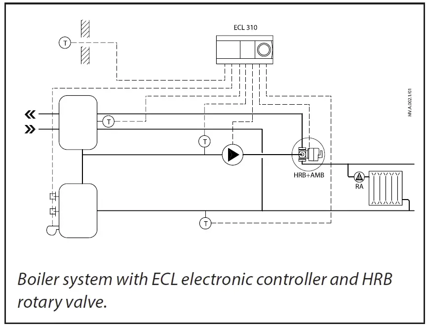
Application principle
Installation procedure
- Rotary valve
- Anti-rotation spacer
- Valve adapter
- Actuator
- Manual operating clutch
- Position indicator
- Handle
- Fixing screw
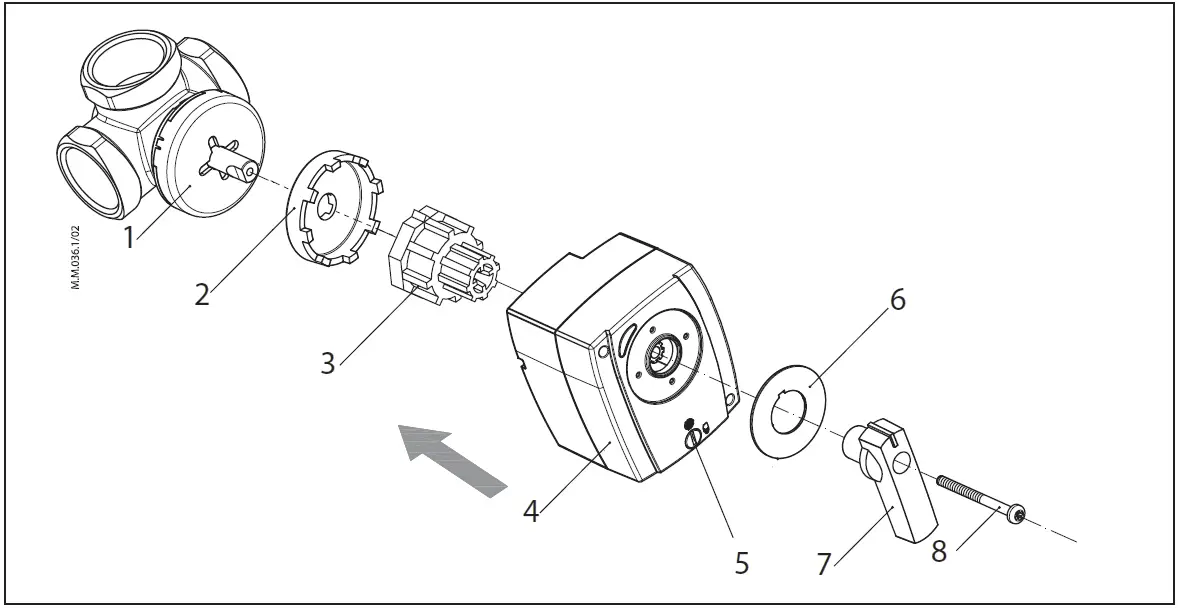
INSTALLTION
The actuator can be mounted directly to the rotary valve. Rotating angle is limited to 90° and when the actuator reaches the limit, the voltage supply to the actuator is disconnected.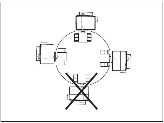
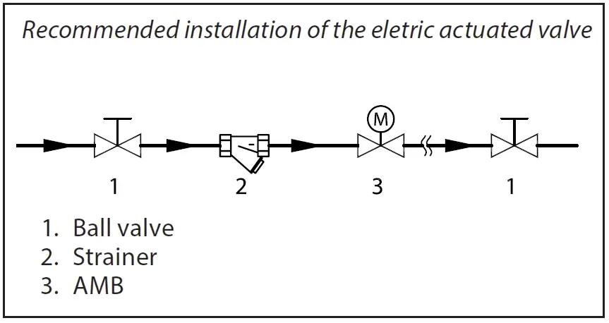
Hydraulic installation
Manual override
LED signalling

Wiring
DIP switch setting
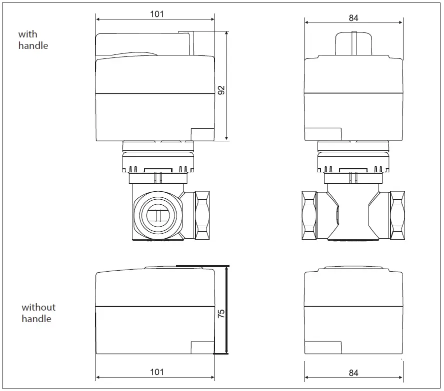
Dimensions
MORE INFORMATION
Danfoss can accept no responsibility for possible errors in catalogues, brochures and other printed material. Danfoss reserves the right to alter its products without notice. This also applies to products already on order provided that such alterations can be made without subsequent changes being necessary in specifications already agreed. All trademarks in this material are property of the respective companies. Danfoss and the Danfoss logotype are trademarks of Danfoss A/S. All rights reserved.
FAQs
- Q: What do the LED colors indicate?
- A: The orange LED indicates rotation left, green/red LED indicates rotation right, and orange/green/red LED indicates status OK.
- Q: How do I activate the AUX switch?
- A: AUX switch activation can be done by following the instructions provided in the user manual. Ensure proper connections are made as per the guidelines.
Documents / Resources
 |
Danfoss AMB 162 Actuator For Temperature Control In Central Heating Systems [pdf] Installation Guide 162, 182, AMB 162 Actuator For Temperature Control In Central Heating Systems, AMB 162, Actuator For Temperature Control In Central Heating Systems, Temperature Control In Central Heating Systems, Central Heating Systems, Heating Systems, Systems |