
Danfoss AFPQ 4 Flow Controller User Guide
AFPQ (4) / VFQ 2(1) DN 15-250
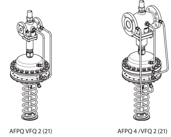
AFPQ (4) / VFQ 2(1)


Safety Notes
Prior to assembly and commissioning to avoid injury of persons and damages of the devices, it is absolutely necessary to carefully read and observe these instructions.
Necessary assembly, start-up, and maintenance work must be performed only by qualified, trained and authorized personnel.
Prior to assembly and maintenance work on the controller, the system must be:
- depressurized,
- cooled down,
- emptied and
- cleaned.
Please comply with the instructions of the system manufacturer or system operator.
Definition of Application
The controller is used for flow rate limitation and differential pressure control of water and water glycol mixtures for heating, district heating and cooling systems.
The technical data on the rating plates determine the use.
Scope of Delivery
FIG 1
Accessory, for connection to flow supply and return flow
Assembly
Admissible Installation Positions FIG (2)
DN 15-80
media temperatures up to 120 °C:
Can be installed in any position.
DN 100–250 all temperatures and DN 15-80 media temperatures > 120 °C:
Installation only permitted in horizontal pipelines with the actuator hanging downwards.
Installation Location and
Installation Scheme FIG (3)
AFPQ/VFQ 2(1) return flow mounting
AFPQ 4/VFQ 2(1) supply flow mounting
Valve Installation FIG (4)
- Install strainer ① before the controller.
- Rinse system prior to installing the valve.
- Observe flow direction ② on the valve body


Impulse Tube Mounting to Supply Flow AFPQ


Insulation
FIG 10

Dismounting
FIG 11

Leak and Pressure Tests
FIG 12

Filling the System, First Start-up
FIG 13

Set-point Setting


Adjustment with flow adjusting curves

Note
The adjustment may be checked when the system is running by means of a heat meter, see next section.
Flow Adjusting Curves
FIG 17

Flow rate is too low, what to do?
Remedy:
1. Verify adjustment, see section before.
2. Check differential pressure at the control valve.

Dimensions, Weights
FIG 18
Flanges: connection dimensions acc. too DIN 2501, seal form C
Danfoss A/S
Climate Solutions • climatesolutions.danfoss.com • +45 7488 2222 • E-Mail: climatesolutions@danfoss.com
Any information, including, but not limited to information on selection of product, its application or use, product design, weight, dimensions, capacity or any other technical data in product manuals, catalogues descriptions, advertisements, etc. and whether made available in writing, orally, electronically, online or via download, shall be considered informative, and is only binding if and to the extent, explicit reference is made in a quotation or order confirmation. Danfoss cannot accept any responsibility for possible errors in catalogues, brochures, videos and other material.
Danfoss reserves the right to alter its products without notice. This also applies to products ordered but not delivered provided that such alterations can be made without changes to form, fit or function of the product.
All trademarks in this material are property of Danfoss A/S or Danfoss group companies. Danfoss and the Danfoss logo are trademarks of Danfoss A/S. All rights reserved.
20 | © Danfoss | DCS-SGDPT/SI | 2022.12
Read More About This Manual & Download PDF:
Documents / Resources
 |
Danfoss AFPQ 4 Flow Controller [pdf] User Guide AFPQ 4, VFQ 2 1, VFQ 2 DN 15-125, VFQ 2 DN 150-250, AFPQ 4 Flow Controller, AFPQ 4, Flow Controller, Controller |