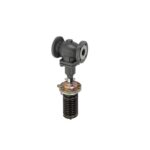
AFA 2 Pressure Relief Controller
“
Product Specifications
- Model: AFA 2 / VFG 2(1) DN 15-250, VFG 22(1) DN 65-250
- Maintenance: Maintenance Free
- Adapter: 003G1780*
- Pressure Range: PN 16, PN 25, PN 40
- Materials: EN-GJL-250 (GG-25), EN-GJS-400 (GGG-40.3),
EN-GP-240-GH (GS-C 25) - Actuator Weight: AFA 2 PN 16 – 10kg, AFA 2 PN 40 – 9kg
Product Usage Instructions
Safety Notes
Prior to assembly and commissioning, read and observe the
instructions to avoid injury or device damage. Only qualified
personnel should perform assembly, start-up, and maintenance work.
Ensure the system is depressurized, cooled down, emptied, and
cleaned before any maintenance.
Application
The controller is designed for pressure relief of water and
water glycol mixtures in heating, district heating, and cooling
systems.
Assembly and Installation
- Ensure the system is depressurized, cooled down, emptied, and
cleaned. - Follow the instructions provided by the system manufacturer or
operator. - Install the controller according to the specified DN size and
pressure range.
Maintenance
The product is maintenance-free, reducing the need for regular
upkeep.
Frequently Asked Questions (FAQ)
1. What are the recommended safety measures before using the
product?
Before assembly and commissioning, ensure the system is
depressurized, cooled down, emptied, and cleaned to avoid injury or
damage.
2. What is the application of the controller?
The controller is used for pressure relief of water and water
glycol mixtures in heating, district heating, and cooling
systems.
3. How should I handle maintenance of the product?
The product is maintenance-free, reducing the need for regular
upkeep. However, if any issues arise, consult qualified personnel
for assistance.
“`
Operating Guide
AFA 2 / VFG 2(1) DN 15-250 VFG 22(1) DN 65-250
AFA 2 / VFG 2(1) / VFG 22(1) / 73695690
ENGLISH DEUTSCH FRANÇAIS ITALIANO
CESKY POLSKI
AFA 2 / VFG 2(1) DN 15-250, VFG 22(1) DN 65-250 AFA 2 / VFG 2(1) DN 15-250, VFG 22(1) DN 65-250 AFA 2 / VFG 2(1) DN 15-250, VFG 22(1) DN 65-250 AFA 2 / VFG 2(1) DN 15-250, VFG 22(1) DN 65-250 AFA 2 / VFG 2(1) DN 15-250, VFG 22(1) DN 65-250 AFA 2 / VFG 2(1) DN 15-250, VFG 22(1) DN 65-250 AFA 2 / VFG 2(1) DN 15-250, VFG 22(1) DN 65-250 AFA 2 / VFG 2(1) DN 15-250, VFG 22(1) DN 65-250
www.danfoss.com www.danfoss.de www.danfoss.fr www.danfoss.it www.danfoss.cz www.danfoss.pl www.danfoss.ru www.danfoss.cn
Page 7 Seite 8 Page 9 Pagina 10 Strana 12 Strona 13 14 16
virtus.danfoss.com © Danfoss | 2025.02
AQ36277258032801-000103 | 1
AFA 2 / VFG 2(1) DN 15-250, VFG 22(1) DN 65-250
MAINTENANCE FREE
DN 15-250
Tmax = 150 °C
DN 65-250 Tmax = 150 °C
3 mm
SW13, 19, 36, 46
DN 15-250 Tmax = 200 °C
Bellows VFG2, VFG21
adapter 003G1780*
AFA 2
AF (1×)**
Tmax 150 °C VFG 22 (221) VFG 2 (21) DN 15-50
Piston VFG22, VFG221
Bellows VFG2
adapter 003G1780*
AFA 2
AFA 2 1×
V1, V2 (630 cm2)
AF (1×)**
Tmax > 150 °C
AF (2×)**
2 | © Danfoss | 2025.02
AQ36277258032801-000103
AFA 2 / VFG 2(1) DN 15-250, VFG 22(1) DN 65-250
FV
AFA 2/VFG 22(1) DN 65-250
Turn
till
and
~ 30 turns
Pull out
Release
for ½ turn
Fix
SW46 Max 100-120 Nm
Hold
AQ36277258032801-000103
© Danfoss | 2025.02 | 3
AFA 2 / VFG 2(1) DN 15-250, VFG 22(1) DN 65-250
G 1/4
AF
SW 13
SW 19 40 Nm
T < 120 °C
SW 19 40 Nm
T > 150 °C
AFA 2/VFG 22(1) DN 65-250
T > 120 °C
~30 Turns
~30 Turns
4 | © Danfoss | 2025.02
AQ36277258032801-000103
AFA 2 / VFG 2(1) DN 15-250, VFG 22(1) DN 65-250
PN 16
EN-GJL-250 (GG-25)
PN 25
EN-GJS-400 (GGG-40.3)
PN 40
EN-GP-240-GH (GS-C 25)
Type: AFP 2 Code Nr.: 003G5650 p: 1-3 bar, Tmax: 150 °C Area (cm2): 80
Turn
till end
~ 30 turns
Pull out
Fix
SW46 Max 100-120 Nm
Release
for ½ turn
Hold
p = 1-3 bar
AQ36277258032801-000103
© Danfoss | 2025.02 | 5
AFA 2 / VFG 2(1) DN 15-250, VFG 22(1) DN 65-250
SW36
2x
SW36
L
L
H B H B HV HA
ØA VFG 2 (21) DN 15-250
Adapter 003G1780
L
B
H
DN
mm
15 130 213 267
20 150 213 267
25 160 239 304
32 180 239 304
40 200 241 323
50 230 241 323
65 290 245 370
80 310 240 365
100 350 275 435
125 400 270 435
200 600 365 610
250 730 420 680
VFG 22(221) DN 65-250
DN L
B
H
HV
Weight PN 16 PN 25 PN 40
mm
kg
65 290 245 370 285 24 24 27
80 310 240 365 290 29 29 32
100 350 275 425 350 47 48 53
125 400 270 435 370 60 60 68
150 480 330 520 460 105 106 121
200 600 365 610 550 204 206 235
250 730 420 680 620 343 350 404
AFA 2 Actuator
Size ØA HA
Weight (kg)
(cm2)
mm AFA 2 PN 16 AFA 2 PN 40
32 80
175
490 490
10 9
17 16
160 230 490 12,5
25
320 300 490
17
37
640 300 610
40
58
Total installation height of the controller (VFG 22(1) valve + AFA 2 pressure actuator) is sum of HV and HA
ø60 Ø10
Ø 89 Ø 140 40 SW 22
110
6 | © Danfoss | 2025.02
240 Seal pot V1
298 Seal pot V2
G1/4 SW19 Compression fitting
78 Shut off valve
AQ36277258032801-000103
AFA 2 / VFG 2(1) DN 15-250, VFG 22(1) DN 65-250
ENGLISH
Safety Notes Prior to assembly and commissioning to avoid injury of persons and damages of the devices, it is absolutely necessary
to carefully read and observe these instructions.
Necessary assembly, start-up, and maintenance work must be performed only by qualified, trained and authorized personnel.
Prior to assembly and maintenance work on the controller, the system must be:
– depressurized, – cooled down, – emptied and – cleaned.
Please comply with the instructions of the system manufacturer or system operator. Definition of Application The controller is used for pressure relief of water and water glycol mixtures for heating, district heating and cooling systems.
The technical data on the label plates determine the use.
Scope of Delivery *) adapter 003G1780, accessory sold separately, **) Impulse tube AF, accessory sold separately
Assembly
Admissible Installation Positions
media temperatures up to 150 °C: Can be installed in any position.
media temperatures > 150 °C. Installation permitted only in horizontal pipelines with the actuator oriented downwards.
Installation Location and Installation Scheme
The valve is closed without pressure and is opening on rising pressure before the valve.
Valve Installation 1. Install strainer before the controller. 2. Rinse system prior to installing the valve. 3. Observe flow direction on valve body.
Flanges in the pipeline must be in parallel position and sealing surfaces must be clean and without any damage.
4. Install valve. 5. Tighten screws crosswise in 3 steps up to the
max. torque.
Actuator Installation
The actuator stem must be screwed into the valve stem. Spring on the pressure actuator is factory adjusted (stressed).
1. Remove the spindle protection cup and release the valve spindle by removing the nut, washer and cardboard tube.
2. Align the actuator stem with the valve stem, connect both stems and turn gently the whole pressure actuator clockwise with both hands, until the stems are fully connected (valve stem fully screwed into the actuator stem).
3. Release spring (unstress) and release the uninon nut by pulling out the blocking spring.
4. Tight the union nut by hand or with wrench key using minimal force
5. Release the pressure actuator by turning it counter clockwise for approximately half a turn.
6. Observe the position of impulse tubes connection to the valve and align the actuator accordingly.
7. Hold the actuator in the position and tight the union nut to the valve with 100- 120 Nm
torque.
Impulse Tube mounting · Which impulse tubes to use?
The impulse tube set AF (2×) can be used: Order No.: 003G1391 or use the following pipes:
Steel / Stainless steel
Copper
Ø 10×1 Ø 10×1
ISO 1127 D3/T3
Cu-DHP R200 EN12449
· The impulse tube can be connected directly to the valve or to the pipeline . ventilation socket, do not connect impulse tube.
Connection to the valve 1. Remove plug at the valve. 2. Screw in threaded joint G 1/4 with copper
seal, Torque 40 Nm.
– or –
Connection to the Pipeline No connection downwards/upwards , could bring dirt/air into an impulse tube. 1. Cut pipe in rectangular sections and
deburr. 2. For copper pipe:
insert sockets on both sides. 3. Verify the correct position of the cutting
ring . 4. Press impulse tube into the threaded joint
up to its stop. 5. Tighten union nut Torque 40 Nm.
When installing seal pots , please observe the Installation Instructions for the seal pots.
Insulation For media temperatures up to 120 °C the pressure actuator may be insulated . Dismounting
Danger Danger of injury by hot water
Prior to dismounting depressurize system or use shut off valves on the impulse tubes!
Carry out dismounting in following steps:
1. Fasten pressure actuator with the safety bands to the fixed points in surroundings
2. Before releasing the actuator, fully release the union nut
3. Hold the pressure actuator with both hands, and release it by turning it counter clockwise ~30 turns. During turning, control the actuator weight all the time to prevent unexpected fall of detached actuator.
4. Carefully remove the actuator from the valve.
Before installing actuator back to the valve, setting spring must be fully released again.
Leak and Pressure Test
Observe max. permitted pressure, see below.
The pressure behind the valve must not exceed the pressure before the valve .
Observe nominal pressure of the valve.
Caution: The valve is closed without pressure and it opens on rising pressure before the valve.
Prior to pressure tests, it is absolutely necessary to remove the impulse tube at the valve . Close connections with plugs G ¼ ISO 228.
Max. pressure [bar] with connected impulse tube:
AFA 2 cm2 32
bar
16
80 160 320 640
5
2.5 1.3 0.35
Max. test pressure with disconnected impulse tube must not exceed the plant testing pressure and must always be lower than 1.5 × PN.
Non-compliance may cause damages at the controller .
Filling the System, Start-up
The pressure behind the valve must not exceed the pressure before the valve.
Non-compliance may cause damages at the controller .
1. Open shut-off devices that are possibly available at the impulse tubes .
2. Slowly open valves in the system. 3. Slowly open shut-off device . 4. Slowly open shut-off device .
Putting out of Operation 1. Slowly close shut-off device . 2. Slowly close shut-off device .
Setpoint Adjustment 1. Set-point range see rating plate 2. Start-up of system, see section . 3. Start pump 4. Observe pressure indicator 5. Slightly close fitting behind the pump (in
flow direction) so that the pressure is rising. 6. Adjustment of the pressure in front of the valve
· Turning to the right reduces the set-point (unstressing the spring – tension spring)
· Turning to the left increases the set-point (stressing the spring)
7. If the required pressure cannot be set, further close the fitting .
8. The set-point adjuster may be sealed. 9. Release the not yet used pointer , move it
to the set position and fix it with the screw to mark setting position
Dimensions Flanges: connection dimensions acc. to
DIN 2501, seal form C
AQ36277258032801-000103
© Danfoss | 2025.02 | 7
AFA 2 / VFG 2(1) DN 15-250, VFG 22(1) DN 65-250
DEUTSCH
Sicherheitshinweise Um Verletzungen von Personen und Schäden am Gerät zu vermeiden, ist es absolut notwendig, dass vor Montage
und Inbetriebnahme diese Anleitung sorgfältig gelesen und die Anweisungen befolgt werden.
Notwendige Montage-, Inbetriebnahmeund Wartungsarbeiten dürfen nur von qualifiziertem, geschultem und autorisiertem Personal durchgeführt werden.
Vor Montage- und Wartungsarbeiten am Regler muss das System
– drucklos, – abgekühlt, – entleert und – gereinigt sein.
Die Anweisungen des Systemherstellers oder Netzbetreibers müssen befolgt werden.
Bestimmungsgemäße Verwendung Der Regler dient zur Druckentlastung von Wasser und Wasser-Glykol-Gemischen in Heizungs-, Fernwärme- und Kühlungsanlagen.
Die technischen Daten auf den Kennzeichnungsschildern sind für die Verwendung maßgebend.
Lieferumfang *) Adapter 003G1780, Zubehör separat
erhältlich, **) Steuerleitungsset AF, Zubehör separat
erhältlich.
Montage
Zulässige Einbaulagen
Medientemperaturen bis 150 °C. Beliebige Einbaulage.
Medientemperaturen >150 °C. Einbau nur in waagerecht verlaufenden Rohrleitungen mit nach unten gerichtetem Druckantrieb zulässig.
Einbauort und Einbauschema
Ohne Druck bleibt das Ventil geschlossen und öffnet bei steigendem Druck vor dem Ventil.
Einbau des Ventils 1. Schmutzfänger vor dem Regler einbauen. 2. Anlage vor dem Einbau des Ventils spülen. 3. Durchflussrichtung auf dem
Ventilgehäuse beachten.
Flansche in der Rohrleitung müssen parallel angeordnet, Dichtflächen müssen sauber und unbeschädigt sein.
4. Ventil einbauen. 5. Schrauben über Kreuz in 3 Schritten
bis zum max. Drehmoment anziehen.
Einbau des Druckantriebes
Die Druckantriebsstange muss in die Ventilstange eingeschraubt werden. Die Feder am Druckantrieb ist ab Werk voreingestellt (gespannt).
1. Spindelschutzkappe entfernen und Ventilspindel durch Entfernen von Mutter, Unterlegscheibe und Papprohr lösen.
2. Antriebsstange auf die Kegelstange des Ventiles ausrichten, beide Stangen verbinden und den gesamten Druckantrieb mit beiden Händen leicht im Uhrzeigersinn drehen, bis die Stangen vollständig verbunden sind (Ventilstange vollständig in die Antriebsstange eingeschraubt, ca. 30 Umdrehungen).
3. Feder lösen (entspannen) und Überwurfmutter durch Herausziehen der Sperrfeder lösen.
4. Überwurfmutter mit minimalem Kraftaufwand von Hand oder mit Schlüssel anziehen.
5. Druckantrieb durch Drehen gegen den Uhrzeigersinn (ca. eine halbe Umdrehung) lösen.
6. Stellung der Steuerleitungsanschlüsse zum Ventil beachten und Druckantrieb entsprechend ausrichten.
7. Druckantrieb in Position halten und Überwurfmutter mit 100120 Nm
Drehmoment am Ventil festschrauben.
Montage der Steuerleitung · Welche Steuerleitungen können verwendet
werden? Das Steuerleitungsset AF (1×) kann verwendet werden: Best.-Nr: 003G1391 oder folgende Rohre verwenden:
Stahl/ Edelstahl
Kupfer
Ø10 × 1 Ø10 × 1
ISO 1127 D3/T3
Cu-DHP R200 EN12449
· Die Steuerleitung kann direkt an das Ventil oder an die Rohrleitung angeschlossen werden. Belüftungsstutzen, Steuerleitung nicht anschließen.
Anschluss am Ventil 1. Stopfen am Ventil entfernen. 2. Verschraubung G ¼ mit Kupferdichtung
eindrehen, Drehmoment 40 Nm.
oder
Anschluss an die Rohrleitung Kein Anschluss nach unten/oben , um Schmutz- bzw. Lufteintrag in die Steuerleitung zu vermeiden. 1. Rohr rechtwinklig ablängen und
entgraten. 2. Bei Kupferrohr:
Einsteckhülsen beidseitig einfügen. 3. Die korrekte Position des Schneidrings
überprüfen . 4. Steuerleitung bis zum Anschlag in
die Verschraubung drücken. 5. Überwurfmutter anziehen ,
Drehmoment 40 Nm.
Bei Einbau von Vorlagegefäßen Montageanleitung für Vorlagegefäße beachten.
Wärmedämmung Bei Medientemperaturen bis 120 °C kann der Druckantrieb isoliert werden . Demontage des Druckantriebes
Gefahr Verletzungsgefahr durch Heißwasser
Vor der Demontage Anlage drucklos machen oder Absperrventile in den Steuerleitungen absperren!
Zur Demontage folgende Schritte durchführen: 1. Druckantrieb mit Sicherheitsbändern an
entsprechenden Punkten in der Umgebung fixieren. 2. Vor dem Lösen des Druckantriebs die Überwurfmutter vollständig lösen. 3. Den Druckantrieb mit beiden Händen festhalten und durch Drehen gegen den Uhrzeigersinn (ca. 30 Umdrehungen) lösen. Beim Drehen das Gewicht des Druckantriebes kontinuierlich beachten, um ein unbeabsichtigtes Herunterfallen zu vermeiden. 4. Druckantrieb vorsichtig vom Ventil lösen.
Vor der erneuten Montage des Druckantriebes am Ventil muss die Feder wieder vollständig entspannt werden.
Dichtheits- und Druckprüfung
Max. zulässige Drücke beachten,
siehe unten.
Der Druck hinter dem Ventil darf den Druck vor dem Ventil nicht überschreiten.
Nenndruck des Ventils beachten.
Achtung: Ohne Druck bleibt das Ventil geschlossen und es öffnet bei steigendem Druck vor dem Ventil.
Vor Druckprüfungen ist es zwingend erforderlich, die Steuerleitung am Ventil zu entfernen. Die Anschlüsse mit Stopfen G ¼ ISO 228 schließen.
Max. Druck [bar] mit angeschlossener Steuerleitung:
AFA 2 cm2 32
bar
16
80 160 320 640
5
2,5 1,3 0,35
Der max. Prüfdruck mit getrennter Steuerleitung darf den Prüfdruck der Anlage nicht überschreiten und muss immer kleiner als 1,5 × PN sein.
Nichtbeachtung kann zu Schäden am Regler führen.
8 | © Danfoss | 2025.02
AQ36277258032801-000103
AFA 2 / VFG 2(1) DN 15-250, VFG 22(1) DN 65-250
Befüllung der Anlage, Inbetriebnahme
Der Druck hinter dem Ventil darf
den Druck vor dem Ventil nicht
überschreiten.
Nichtbeachtung kann zu Schäden am Regler führen.
1. Absperrarmaturen, die eventuell an den Steuerleitungen vorhanden sind, öffnen.
2. Ventile in der Anlage langsam öffnen. 3. Absperrarmaturen langsam öffnen. 4. Absperrarmaturen langsam öffnen.
Außerbetriebnahme 1. Absperrarmaturen langsam schließen. 2. Absperrarmaturen langsam schließen.
Sollwertanpassung 1. Sollwertbereich siehe Typenschild . 2. Inbetriebnahme der Anlage,
siehe Abschnitt . 3. Pumpe starten. 4. Druckanzeigen beachten . 5. Armatur hinter der Pumpe leicht
schließen (Durchflussrichtung), sodass der Druck steigt. 6. Einstellung des Druckes vor dem Ventil · Rechtsdrehung senkt den Sollwert
(Feder entspannen Zugfeder) · Linksdrehung erhöht den Sollwert
(Feder spannen) 7. Falls der geforderte Druck nicht
einstellbar ist, die Armatur weiter schließen. 8. Der Sollwertsteller kann plombiert werden. 9. Den verwendeten Zeiger noch nicht lösen , sondern in die eingestellte Position bewegen und mit der Schraube fixieren, um Nullposition zu markieren.
Abmessungen Flansche: Anschlussmaße nach DIN 2501,
Dichtung Form C
FRANÇAIS
Consignes de sécurité Pour éviter qu’une personne se blesse et que les appareils soient endommagés, il est absolument
nécessaire de lire attentivement ces instructions avant l’assemblage et la mise en service, et de les respecter.
Les travaux d’assemblage, de démarrage et de maintenance nécessaires doivent être effectués uniquement par du personnel qualifié, formé et autorisé.
Avant tout travail d’assemblage et de maintenance du régulateur, le système doit être :
– dépressurisé, – refroidi, – vidangé et – nettoyé.
Suivre les instructions du concepteur ou de l’opérateur du système.
Conditions d’utilisation Le régulateur est utilisé pour réguler la pression amont sur des circuits de chauffage ou d’eau glacée.
Les données techniques sur les plaques signalétiques sont déterminantes pour l’utilisation.
Contenu de la livraison *) Adaptateur 003G1780, accessoire vendu
séparément, **) Tube d’impulsion AF, accessoire vendu
séparément.
Montage
Positions de montage autorisées
Températures des fluides jusqu’à 150 °C : peut être installé dans n’importe quelle position.
Températures de fluides supérieures à 150 °C. Montage autorisé uniquement dans des tuyauteries horizontales où l’actionneur est orienté vers le bas.
Emplacement et schéma d’installation
La vanne est fermée sans pression et s’ouvre lorsque la pression augmente avant la vanne.
Installation de la vanne 1. Monter le filtre avant le régulateur. 2. Rincer le système avant le montage du corps
de la vanne. 3. R especter le sens de circulation indiqué
sur le corps de vanne.
Les brides sur la tuyauterie doivent être parallèles et les surfaces d’étanchéité propres et intactes.
4. Installer le corps de la vanne. 5. Serrer les vis en 3 étapes en diagonale,
jusqu’au couple de serrage maximal.
Installation de l’actionneur
La tige de l’actionneur doit être vissée sur la tige de la vanne. Le ressort de l’actionneur pressostatique est réglé en usine (relâché).
1. Retirer la coupe de protection de la tige et libérer la tige de la vanne en enlevant l’écrou, la rondelle et le tube en carton.
2. Aligner la tige de l’actionneur avec la tige de la vanne. Connecter les deux tiges et tourner doucement l’intégralité de l’actionneur pressostatique dans le sens des aiguilles d’une montre à deux mains, jusqu’à ce que les tiges soient complètement connectées (tige entièrement vissée dans la tige de l’actionneur).
3. Libérer le ressort (détendu) et l’écrou en tirant sur le ressort de blocage pour le retirer.
4. Serrer l’écrou à la main ou avec une clé en serrant très peu.
5. Relâcher l’actionneur pressostatique en le tournant dans le sens inverse des aiguilles d’une montre d’environ un demi-tour.
6. Observer la position du raccord des tubes d’impulsion à la vanne et aligner l’actionneur en conséquence.
7. Maintenir l’actionneur dans la position et serrer l’écrou à la vanne selon un couple
de serrage de 100 – 120 Nm.
Installation du tube d’impulsion · Quels tubes d’impulsion utiliser ?
L’ensemble de tubes d’impulsion AF (2×) peut être utilisé : Référence : 003G1391 ou les tubes suivants peuvent être utilisés :
Acier/Acier inoxydable
Cuivre
Ø 10 × 1 Ø 10 × 1
ISO 1127 D3/T3
Cu-DHP R200 EN12449
· Le tube d’impulsion peut être raccordé directement sur la vanne ou à la conduite . Prise de pression atmosphérique. Ne pas brancher le tube d’impulsion.
Raccordement à la vanne 1. Retirer le bouchon de la vanne. 2. Visser le raccord fileté G ¼ avec joint
en cuivre, couple 40 Nm.
– ou –
Raccordement à la tuyauterie Aucun raccordement vers le bas/le haut , pourrait faire pénétrer de l’air/de la saleté dans le tube d’impulsion. 1. Couper le tuyau en sections rectangulaires
et ébarber. 2. Pour les tuyaux en cuivre :
insérer les fiches de chaque côté. 3. Vérifier le bon positionnement de l’olive . 4. Enfoncer le tube d’impulsion dans le
raccord fileté jusqu’à la butée. 5. Serrer l’écrou Couple de serrage de 40 Nm.
Lors de l’installation des pots de condensation , respecter les instructions d’installation des pots de condensation.
AQ36277258032801-000103
© Danfoss | 2025.02 | 9
AFA 2 / VFG 2(1) DN 15-250, VFG 22(1) DN 65-250
Isolation Pour des températures de fluide jusqu’à 120 °C, l’actionneur pressostatique peut être isolé . Démontage
Danger Risque de brûlure par l’eau chaude
Avant le démontage, dépressuriser le système ou utiliser des vannes d’arrêt sur les tubes d’impulsion !
Pour le démontage, suivre les étapes suivantes : 1. Fixer l’actionneur pressostatique avec
les bandes de sécurité aux points fixes à proximité. 2. Avant de libérer l’actionneur, desserrer complètement l’écrou. 3. Maintenir l’actionneur de pression avec les deux mains et le relâcher en le tournant d’environ 30 tours dans le sens inverse des aiguilles d’une montre. Pendant la rotation, contrôler en permanence le poids de l’actionneur pour éviter sa chute inattendue une fois détaché. 4. Retirer avec précaution l’actionneur de la vanne.
Avant de réinstaller l’actionneur sur la vanne, le ressort de réglage doit être complètement relâché.
Test d’étanchéité et de pression
Respecter la limite maximale
autorisée (voir ci-dessous).
La pression après la vanne ne doit pas dépasser la pression avant la vanne .
Respecter la pression nominale de la vanne.
Attention : La vanne est fermée sans pression et s’ouvre lorsque la pression augmente en amont de la vanne.
Avant d’effectuer des tests de pression, il est absolument nécessaire de retirer le tube d’impulsion au niveau de la vanne . Fermer les raccordements à l’aide de bouchons G ¼ ISO 228.
Pression maximale [bar] avec tube d’impulsion raccordé :
AFA 2 cm2 32
bar
16
80 160 320 640
5
2,5 1,3 0,35
La pression de test max. avec tube d’impulsion débranché ne doit pas dépasser la pression de test du réseau et doit toujours être inférieure à 1,5 × PN.
Le non-respect de cette consigne peut endommager le régulateur .
Remplissage du système et démarrage
La pression après la vanne
ne doit pas dépasser la pression
avant la vanne.
Le non-respect de cette consigne peut endommager le régulateur .
1. Ouvrir les organes d’arrêt qui sont éventuellement disponibles sur les tubes d’impulsion .
2. Ouvrir lentement les vannes de régulation du réseau.
3. Ouvrir lentement le dispositif d’arrêt . 4. Ouvrir lentement le dispositif d’arrêt .
Mise à l’arrêt 1. Fermer lentement le dispositif d’arrêt . 2. Fermer lentement le dispositif d’arrêt .
Réglage de la valeur de consigne : 1. Plage de consigne, voir plaque
signalétique . 2. Démarrage du système, voir section . 3. Démarrer la pompe . 4. Vérifier l’indication de pression . 5. Fermer légèrement le raccord derrière
la pompe (dans le sens du débit) de manière à ce que la pression augmente. 6. Réglage (de la pression amont de la vanne) · Effectuer une rotation vers la droite
pour augmenter la valeur de consigne (relâchement du ressort – tension du ressort). · Effectuer une rotation vers la gauche pour augmenter la valeur de consigne (tension du ressort). 7. Si la pression requise ne peut pas être réglée, fermer davantage le raccord . 8. La molette de consigne peut être scellée. 9. Libérer l’aiguille pas encore utilisée . La déplacer dans la position définie et la fixer à l’aide de la vis afin de marquer la position de réglage.
Dimensions Brides : dimensions des raccordements selon
la norme DIN 2501, étanchéité forme C
ITALIANO
Note per la sicurezza Prima dell’assemblaggio e della messa in servizio, è assolutamente necessario leggere con attenzione e rispettare
queste istruzioni per evitare infortuni al personale e danni ai dispositivi.
Assemblaggio, avvio e attività di manutenzione devono essere eseguiti solo da personale autorizzato, addestrato e qualificato.
Prima di eseguire le attività di assemblaggio e manutenzione sul regolatore, l’impianto deve essere:
– depressurizzato, – raffreddato, – svuotato e – pulito.
Seguire le istruzioni del costruttore o del gestore dell’impianto.
Descrizione del prodotto Il regolatore è utilizzato per la limitazione della pressione dell’acqua delle miscele acqua glicole negli impianti di riscaldamento, teleriscaldamento e raffrescamento.
I dati tecnici riportati sulla targhetta ne determinano l’uso.
Ambito della fornitura *) Adattatore 003G1780, accessorio venduto
separatamente, **) Tubo di impulso AF, accessorio venduto
separatamente.
Assemblaggio
Posizioni di montaggio consentite
temperatura del mezzo fino a 150 °C. Installabile in qualsiasi posizione.
temperatura del mezzo >150 °C. Installazione consentita solo in tubazioni orizzontali con l’attuatore orientato verso il basso.
Configurazione e schema di installazione
La valvola si chiude senza pressione e si apre all’aumento della pressione prima della valvola.
Installazione della valvola 1. Installare il filtro prima del regolatore. 2. Risciacquare l’impianto prima di installare
la valvola. 3. Osservare la direzione del flusso sul corpo
valvola.
Le flange nella tubazione devono essere in posizione parallela e le superfici di tenuta devono essere pulite e non danneggiate.
4. Installare la valvola. 5. Serrare le viti a sequenza incrociata in tre
passaggi, fino a raggiungere il massimo serraggio.
10 | © Danfoss | 2025.02
AQ36277258032801-000103
AFA 2 / VFG 2(1) DN 15-250, VFG 22(1) DN 65-250
Installazione dell’attuatore
Lo stelo dell’attuatore deve essere avvitato nello stelo della valvola. La molla sull’attuatore di pressione è regolata in fabbrica (sollecitata).
1. Rimuovere il cappuccio di protezione dello stelo e sbloccare lo stelo della valvola rimuovendo il dado, la rondella e il tubo di cartone.
2. Allineare lo stelo dell’attuatore con lo stelo della valvola, collegare entrambi gli steli e ruotare delicatamente con entrambe le mani l’intero attuatore di pressione in senso orario, fino a quando gli steli non sono completamente collegati (stelo della valvola completamente avvitato nello stelo dell’attuatore).
3. Rilasciare la molla (non sollecitata) e allentare il dado di unione estraendo la molla di bloccaggio.
4. Serrare il dado di unione manualmente o con la chiave applicando una forza minima.
5. Allentare l’attuatore di pressione ruotandolo in senso antiorario di circa mezzo giro.
6. Osservare la posizione dell’attacco dei tubi di impulso alla valvola e allineare l’attuatore di conseguenza.
7. Tenere fermo l’attuatore in posizione e serrare il dado di unione sulla valvola
a una coppia di 100-120 Nm.
Montaggio del tubo di impulso · Quali tubi di impulso utilizzare?
Il set del tubo di impulso AF (2×) può essere utilizzato: N. Ordine: 003G1391 in alternativa, è possibile utilizzare i seguenti tubi:
Acciaio/Acciaio inossidabile
Rame
Ø 10 × 1 Ø 10 × 1
ISO 1127 D3/T3
Cu-DHP R200 EN12449
· Il tubo di impulso può essere collegato direttamente alla valvola oppure alla tubazione . Presa di ventilazione, non collegare il tubo di impulso.
Collegamento alla valvola 1. Rimuovere il tappo dalla valvola. 2. Avvitare il giunto filettato G ¼ con la
guarnizione in rame a una coppia di 40 Nm.
– oppure –
Collegamento alla tubazione Nessuna connessione verso il basso/verso l’alto , che potrebbe causare la presenza di sporco/ aria nel tubo di impulso. 1. Tagliare il tubo in sezioni rettangolari
e rimuovere le sbavature. 2. Per tubi in rame:
inserire le prese su entrambi i lati. 3. Verificare il corretto posizionamento
dell’ogiva . 4. Spingere il tubo di impulso all’interno
del giunto filettato fino al punto di arresto. 5. Serrare il dado di unione a una coppia
di 40 Nm.
Per l’installazione dei barilotti di separazione , fare riferimento alle relative istruzioni di installazione.
Coibentazione Per una temperatura del mezzo fino a 120 °C, l’attuatore di pressione può essere coibentato . Smontaggio
Pericolo Pericolo di lesioni causate da acqua calda
Prima dello smontaggio, depressurizzare l’impianto o utilizzare le valvole di intercettazione sui tubi di impulso!
Eseguire le seguenti operazioni di smontaggio: 1. Fissare l’attuatore di pressione con le fasce
di sicurezza ai punti fissi nell’ambiente circostante. 2. Prima di smontare l’attuatore, allentare completamente il dado di unione. 3. Reggere l’attuatore di pressione con entrambe le mani e rilasciarlo ruotandolo in senso antiorario di ~30 giri. Durante la rotazione, controllare sempre il peso dell’attuatore per evitare cadute impreviste dell’attuatore staccato. 4. Rimuovere con cautela l’attuatore dalla valvola.
Prima di rimontare l’attuatore sulla valvola, la molla di regolazione deve essere rilasciata completamente.
Test di tenuta e pressione
Osservare la pressione massima
consentita, vedere di seguito.
La pressione a valle della valvola non deve superare quella a monte della valvola .
Osservare la pressione nominale della valvola.
Attenzione: La valvola si chiude senza pressione e si apre all’aumento della pressione prima della valvola.
Prima dei test di tenuta, è assolutamente necessario rimuovere il tubo di impulso dalla valvola . Chiudere i collegamenti con i tappi G ¼ ISO 228.
Pressione max. [bar] con tubo di impulso collegato:
AFA 2 cm2 32
bar
16
80 160 320 640
5
2,5 1,3 0,35
La pressione di prova massima con tubo di impulso scollegato non deve superare la pressione di prova dell’impianto e deve essere in ogni caso inferiore a 1,5 × PN.
Il mancato rispetto di queste istruzioni potrebbe causare danni al regolatore .
Riempimento del sistema e avvio
La pressione a valle della valvola
non deve superare la pressione
a monte della valvola.
Il mancato rispetto di queste istruzioni potrebbe causare danni al regolatore .
1. Aprire i dispositivi di intercettazione eventualmente disponibili sui tubi di impulso .
2. Aprire lentamente le valvole dell’impianto. 3. Aprire lentamente i dispositivi
di intercettazione . 4. Aprire lentamente i dispositivi
di intercettazione .
Messa fuori servizio 1. Chiudere lentamente i dispositivi
di intercettazione . 2. Chiudere lentamente i dispositivi
di intercettazione .
Regolazione del valore 1. Intervallo valore, vedere targhetta . 2. Avvio del sistema, vedere sezione . 3. Avviare la pompa . 4. Osservare l’indicatore di pressione . 5. Chiudere leggermente il raccordo
dietro la pompa (nella direzione del flusso) in modo che la pressione aumenti. 6. Regolazione della pressione davanti alla valvola · Ruotando verso destra il valore verrà
diminuito (eliminando la sollecitazione della molla – molla di trazione) · Ruotando verso sinistra il valore verrà aumentato (sottoponendo la molla a sollecitazione) 7. Se non è possibile impostare la pressione richiesta , chiudere ulteriormente il raccordo . 8. La manopola di regolazione può essere sigillata. 9. Sganciare il puntatore non ancora utilizzato , spostarlo nella posizione impostata e fissarlo con la vite per contrassegnare la posizione di impostazione.
Dimensioni Flange: dimensioni di collegamento secondo
DIN 2501, forma guarnizione C
AQ36277258032801-000103
© Danfoss | 2025.02 | 11
AFA 2 / VFG 2(1) DN 15-250, VFG 22(1) DN 65-250
CESKY
Bezpecnostní informace Z dvodu maximálního snízení moznosti poranní osob nebo vzniku skod na majetku je bezpodmínecn
nutné se ped vlastní montází a uvedením regulátoru do provozu pecliv seznámit se vsemi zde uvedenými bezpecnostními informaci.
Nezbytné montázní práce, kroky pi uvádní do provozu a opravy mohou provádt pouze kvalifikovaní a proskolení pracovníci, kteí byli pro tuto cinnost urceni.
Ped montází nebo ped pípadnou opravou nebo servisem regulátoru je nutné, aby regulovaný systém sploval následující podmínky:
nebyl pod tlakem, byl dostatecn ochlazen, byl vyprázdnn a byl vycistn.
Postupujte podle návodu výrobce systému nebo jeho provozovatele.
Aplikacní oblast Regulátor je urcen pro snizování tlaku vody a smsi vody s glykolem v systémech vytápní, v systémech centralizovaného zásobování teplem a v chladicích systémech.
Pouzití je urceno technickými údaji na stítcích.
Obsah dodávky *) adaptér 003G1780, píslusenství se prodává
samostatn, **) impulzní trubka AF, píslusenství se prodává
samostatn.
Montáz
Pípustné instalacní polohy
Teploty média do 150 °C. Lze instalovat v jakékoliv poloze.
Teploty média > 150 °C. Regulátor je mozné instalovat pouze na vodorovné cásti potrubí, kdy pohon regulátoru smuje dol.
Umístní a schéma instalace
Ventil se zavírá bez tlaku a otevírá se pi rostoucím tlaku ped ventilem.
Instalace ventilu 1. Nainstalujte sítko ped regulátor. 2. Ped instalací ventilu propláchnte systém. 3. Dodrzujte smr prtoku na tle ventilu.
Píruby u potrubí musí být rovnobzné a tsnicí plochy musí být cisté a bez známek poskození.
4. Nainstalujte ventil. 5. Srouby utahujte kízovým postupem
ve 3 krocích az na max. moment.
Instalace pohonu
Veteno pohonu musí být zasroubováno do díku ventilu. Pruzina na tlakov ovládaném pohonu je nastavena z výroby (stlacená).
1. Demontujte ochranný kryt vetena a uvolnte veteno ventilu odstranním matice, podlozky a lepenkové trubicky.
2. Vyrovnejte veteno pohonu s díkem ventilu, spojte oba díky a jemn otácejte celým tlakov ovládaným pohonem po smru chodu hodinových rucicek obma rukama, dokud nebudou díky pln spojeny (dík ventilu zcela zasroubovaný do vetena pohonu).
3. Uvolnte pruzinu a povolte pevlecnou matici vytazením pojistné pruziny.
4. Utáhnte pevlecnou matici rukou nebo klícem minimální silou.
5. Uvolnte tlakov ovládaný pohon otocením proti smru chodu hodinových rucicek piblizn o polovinu otácky.
6. Sledujte polohu pipojení impulzních trubek k ventilu a píslusným zpsobem pohon vyrovnejte.
7. Drzte pohon v dané poloze a utáhnte pevlecnou matici k ventilu momentem
100120 Nm.
Montáz impulzní trubky · Jaké impulzní trubky pouzít?
Je mozné pouzít sadu impulzních trubek AF (2×) : Obj. císlo: 003G1391 nebo pouzijte následující trubky:
Ocel / nerezová ocel
M
Ø 10 × 1 Ø 10 × 1
ISO 1127 D3/T3
Cu-DHP R200 EN12449
· Impulzní trubku lze pipojit pímo k ventilu nebo k potrubí . ventilacní objímka, nepipojujte impulzní trubku.
Pipojení k ventilu 1. Vyjmte ucpávku u ventilu. 2. Zasroubujte závitový spoj G ¼ s mdným
tsnním, utahovací moment 40 Nm.
nebo
Pipojení na potrubí Nepouzívejte pipojení smrem dol/nahoru , protoze by se do impulzní trubky mohly dostat necistoty nebo vzduch. 1. Uíznte trubku s kolmými konci
a odstrate otepy. 2. Mdná trubka:
nasate objímky na ob strany. 3. Zkontrolujte správnou polohu ezacího
prstence . 4. Impulzní trubku natlacte az nadoraz
do závitového spoje. 5. Utáhnte pevlecnou matici momentem
40 Nm.
Pi instalaci chladicích nádobek postupujte podle návodu k instalaci chladicích nádobek.
Izolace Pi teplot média do 120 °C je mozné tlakov ovládaný pohon také zaizolovat . Demontáz
Nebezpecí Nebezpecí poranní horkou vodou
Ped demontází snizte tlak v systému nebo pouzijte uzavírací ventily na impulzních trubkách!
Demontáz provete v následujících krocích: 1. Upevnte tlakov ovládaný pohon vázacími
pásky k pevným bodm v okolí. 2. Ped uvolnním pohonu zcela povolte
pevlecnou matici. 3. Drzte tlakov ovládaný pohon obma
rukama a uvolnte jej otocením proti smru chodu hodinových rucicek piblizn 30 otácek. Bhem otácení neustále kontrolujte tíhu pohonu, abyste zabránili necekanému pádu oddleného pohonu z výsky na zem. 4. Opatrn vyjmte pohon z ventilu.
Ped nainstalováním pohonu zpt do ventilu je nutné znovu zcela uvolnit nastavovací pruzinu.
Zkouska tsnosti a tlaková zkouska
Dodrzujte max.
pípustný tlak, viz níze.
Tlak za ventilem nesmí pekrocit tlak ped ventilem .
Dodrzujte jmenovitý tlak ventilu.
Pozor: Ventil se zavírá bez tlaku a otevírá se pi rostoucím tlaku ped ventilem.
Ped provedením tlakových zkousek je naprosto nezbytné odstranit impulzní trubku u ventilu . Uzavete pípojky záslepkami G ¼ ISO 228.
Max. tlak [bar] s pipojenou impulzní trubkou:
AFA 2 cm2 32
bar
16
80 160 320 640
5
2,5 1,3 0,35
Max. zkusební tlak s odpojenou impulzní trubkou nesmí pekrocit zkusební tlak zaízení a musí být vzdy nizsí nez 1,5 × PN.
Nedodrzení tchto pravidel mze zpsobit poskození regulátoru .
12 | © Danfoss | 2025.02
AQ36277258032801-000103
AFA 2 / VFG 2(1) DN 15-250, VFG 22(1) DN 65-250
Plnní systému, spustní
Tlak za ventilem nesmí pekrocit tlak ped ventilem.
Nedodrzení tchto pravidel mze zpsobit poskození regulátoru .
1. Otevete uzavírací armatury, které jsou pravdpodobn namontovány na impulzních trubkách .
2. Pomalu otevete ventily v systému. 3. Pomalu otevete uzavírací armaturu . 4. Pomalu otevete uzavírací armaturu .
Odstavení z provozu 1. Pomalu uzavete uzavírací armaturu . 2. Pomalu uzavete uzavírací armaturu .
Nastavení pozadované hodnoty 1. Rozsah zádané hodnoty viz typový stítek . 2. Spustní systému, viz cást . 3. Spuste cerpadlo . 4. Sledujte ukazatel tlaku . 5. Lehce pivete sroubení za cerpadlem
(ve smru prtoku), aby se zvýsil tlak . 6. Nastavení tlaku ped ventilem
· Otácením smrem doprava se nastavená hodnota snizuje (uvolování pruziny tazná pruzina)
· Otácením smrem doleva se nastavená hodnota zvysuje (stlacování pruziny)
7. Pokud není mozné nastavit pozadovaný tlak , dále zavete sroubení .
8. Seizovac nastavené hodnoty mze být zaplombovaný.
9. Uvolnte dosud nepouzívaný ukazatel , posute ho do nastavené polohy a zajistte ho sroubem, aby byla pozice nastavení oznacená.
Rozmry Píruby: rozmry pipojení podle normy
DIN 2501, tsnicí tvar C
POLSKI
Warunki bezpieczestwa Aby nie dopuci do zranienia osób oraz uszkodzenia urzdze naley przed montaem i uruchomieniem
urzdzenia bezwzgldnie zapozna si z niniejszymi instrukcjami i przestrzega zawartych w nich zalece.
Monta, rozruch i czynnoci konserwacyjne mog by dokonywane wylcznie przez wykwalifikowany i uprawniony personel.
Przed przystpieniem do montau i wykonywania czynnoci konserwacyjnych regulatora naley koniecznie:
zrzuci cinienie z ukladu, uklad ochlodzi, opróni i wyczyci.
Naley stosowa si do instrukcji producenta i/lub operatora systemu.
Zastosowanie Regulator jest stosowany do upustowej regulacji cinienia, dla wody oraz wodnego roztworu glikolu w ukladach grzewczych, sieciach cieplnych i ukladach chlodzenia.
Dane techniczne na tabliczkach znamionowych wskazuj zakres zastosowa.
Zakres dostawy *) Adapter 003G1780, akcesoria sprzedawane
oddzielnie, **) Rurka impulsowa AF, akcesoria sprzedawane
oddzielnie
Monta
Dozwolone pozycje montau
temperatura czynnika do 150°C: mona montowa w dowolnym poloeniu.
temperatura czynnika > 150°C: monta dozwolony wylcznie na rurocigach poziomych z silownikiem skierowanym w dól.
Miejsce i schemat montau
Zawór jest zamknity bez cinienia i otwiera si przy wzrocie cinienia powyej wartoci nastawionej przed zaworem.
Monta zaworu 1. Przed regulatorem zainstalowa filtr. 2. Przed montaem zaworu instalacj naley
wypluka. 3. Sprawdzi zgodno kierunku przeplywu
ze strzalk na korpusie zaworu.
Kolnierze znajdujce si na rurocigu musz by ustawione równolegle wzgldem siebie, a powierzchnie uszczelniajce czyste i bez uszkodze.
4. Zamontowa zawór. 5. W 3 krokach dokrci ruby w kolejnoci
po przektnej a do uycia maks. dopuszczalnego momentu obrotowego.
Monta silownika
Trzpie silownika naley wkrci w trzpie zaworu. Spryna na silowniku cinieniowym zostala fabrycznie wyregulowana (naprona).
1. Zdj oslon trzpienia, a nastpnie zwolni trzpie zaworu wykrcajc nakrtk, podkladk oraz tekturow tulej.
2. Zrówna trzpie silownika z trzpieniem zaworu, polczy oba trzpienie i delikatnie obróci obiema rkami caly silownik cinieniowy zgodnie z ruchem wskazówek zegara, a trzpienie zostan calkowicie polczone (trzpie zaworu zostanie calkowicie wkrcony w trzpie silownika).
3. Zwolni spryn (nienaprona) i nakrtk lczc, wycigajc spryn blokujc.
4. Dokrci nakrtk lczc rcznie lub kluczem przy uyciu minimalnej sily.
5. Poluzowa silownik cinieniowy, przekrcajc go o okolo pól obrotu w kierunku przeciwnym do ruchu wskazówek zegara.
6. Zwróci uwag na poloenie polcze rurek impulsowych wzgldem zaworu i odpowiednio spasowa silownik.
7. Przytrzyma silownik w ustalonej pozycji i dokrci nakrtk lczc do zaworu
momentem wynoszcym 100-120 Nm.
Monta rurki impulsowej · Jakie rurki impulsowe zastosowa?
Mona uy zestawu AF rurki impulsowej (2×) : nr katalogowy: 003G1391 lub uy nastpujcych rurek:
Stal / stal nierdzewna
Mied
Ø 10 × 1 Ø 10 × 1
ISO 1127 D3/T3
Cu-DHP R200 EN12449
· Rurka impulsowa moe zosta podlczona bezporednio do zaworu lub do rurocigu . króciec cinienia atmosferycznego, nie podlcza rurki impulsowej.
Podlczanie do zaworu 1. Wykrci korek z zaworu. 2. Wkrci zlcze gwintowane G ¼
z uszczelk miedzian stosujc moment obrotowy 40 Nm.
— lub —
Podlczanie do rurocigu Nie podlcza w pozycji w gór/w dól moe to powodowa dostawanie si zanieczyszcze/ powietrza do rurki impulsowej. 1. Uci rurk pod ktem prostym ,
a nastpnie wygladzi krawdzie. 2. W przypadku rurek miedzianych:
wstawi tuleje zaciskowe na obu kocach. 3. Sprawdzi poprawno poloenia piercienia
zaciskajcego . 4. Wcisn do oporu rurk impulsow
w zlcze gwintowane. 5. Dokrci nakrtk lczc stosujc
moment obrotowy 40 Nm.
Podczas montau naczy kondensacyjnych postpowa zgodnie z dolczonymi do nich instrukcjami montau.
AQ36277258032801-000103
© Danfoss | 2025.02 | 13
AFA 2 / VFG 2(1) DN 15-250, VFG 22(1) DN 65-250
Izolacja W przypadku, gdy temperatura czynnika nie bdzie przekraczala 120°C, silownik cinieniowy moe zosta zaizolowany . Demonta
Niebezpieczestwo Niebezpieczestwo poparzenia gorc wod
Przed przystpieniem do demontau naley zrzuci z ukladu cinienie lub uy zaworów odcinajcych umieszczonych na rurkach impulsowych!
W celu dokonania demontau naley wykona nastpujce czynnoci: 1. Uywajc opasek zabezpieczajcych
przymocowa silownik cinieniowy do znajdujcych si w pobliu elementów stalych. 2. W celu demontau silownika naley calkowicie odkrci nakrtk lczc. 3. Przytrzyma silownik cinieniowy obiema rkami i zwolni go, obracajc w lewo o okolo 30 obrotów. Podczas obracania przez caly czas kontrolowa ciar silownika, aby zapobiec jego nieoczekiwanemu upuszczeniu. 4. Ostronie zdj silownik z zaworu.
Przed ponown instalacj silownika na zaworze naley ponownie calkowicie zwolni spryn nastawcz.
Próba szczelnoci i cinienia
Przestrzega maks. dopuszczalnego
cinienia, patrz poniej.
Warto cinienia za zaworem nie moe przekracza wartoci cinienia przed zaworem .
Sprawd cinienie nominalne na zaworze.
Uwaga: Zawór jest zamknity bez cinienia i otwiera si przy wzrocie cinienia przed nim powyej wartoci nastawionej.
Przed przystpieniem do prób cinieniowych absolutnie niezbdne jest wymontowanie rurki impulsowej na zaworze . Zalepi przylcza przy pomocy korków zalepiajcych G ¼ ISO 228.
Maks. warto cinienia [bar] przy podlczonej rurce impulsowej:
AFA 2 cm2 32
bar
16
80 160 320 640
5
2,5 1,3 0,35
Maks. warto cinienia próbnego przy odlczonej rurce impulsowej nie moe przekroczy wartoci cinienia próbnego instalacji i zawsze powinna by nisza ni 1,5 × PN.
Nieprzestrzeganie tego zalecenia moe spowodowa uszkodzenie regulatora .
Napelnianie ukladu, rozruch
Cinienie za zaworem
nie moe przekracza cinienia
przed zaworem.
Nieprzestrzeganie tego zalecenia moe spowodowa uszkodzenie regulatora .
1. Powoli otworzy armatur odcinajc, o ile zostala zamontowana na rurkach impulsowych .
2. Powoli otworzy zawory w ukladzie. 3. Powoli otworzy armatur odcinajc . 4. Powoli otworzy armatur odcinajc .
Wylczenie z eksploatacji 1. Powoli zamkn armatur odcinajc . 2. Powoli zamkn armatur odcinajc .
Wykonanie nastawy cinienia 1. Zakres nastawy jest widoczny na tabliczce
znamionowej . 2. Rozruch ukladu, patrz sekcja . 3. Uruchomi pomp . 4. Obserwowa wskazania manometru . 5. Lekko przymkn zawór za pomp
(w kierunku przeplywu), tak aby cinienie wzroslo. 6. Wykona nastaw cinienia przed zaworem. · Obracanie w prawo zmniejsza
warto nastawy (luzowanie spryny, spryna nacigowa) · Obracanie w lewo zwiksza wartoci nastawy (ciskanie spryny) 7. Jeli nie mona ustawi wymaganego cinienia , zamkn zawór . 8. Nastawnik moe zosta zaplombowany. 9. Poluzowa nieuywany dotd wskanik , przesun go do pozycji nastawy i zamocowa za pomoc ruby, aby zaznaczy poloenie nastawy.
Wymiary Kolnierze: wymiary polcze zgodne z norm
DIN 2501, uszczelka typu C
.
, , .
:
, , .
.
, .
, .
*) 003G1780,
, **) AF,
.
150 °C: .
> 150 °C: .
.
1.
. 2.
. 3.
.
, .
4. . 5.
3 .
14 | © Danfoss | 2025.02
AQ36277258032801-000103
AFA 2 / VFG 2(1) DN 15-250, VFG 22(1) DN 65-250
. () .
4. .
5. 40 ·.
.
1. , , .
2. , , ( ).
3. () , .
4. , .
5. , -.
6. .
7.
100120 ·.
· ?
AF (2×) ( 003G1391) :
/
Ø 10 × 1 Ø 10 × 1
ISO 1127 D3/T3
Cu-DHP R200 EN12449
· . , .
1. . 2. G¼
, 40 ·.
— —
, / . 1.
. 2. :
. 3. , .
120 °C .
–
!
: 1.
. 2. , . 3. , , ~30 . , . 4. .
.
. , . .
.
.
! .
. G¼ ISO 228.
. [] :
AFA 2 2 32
16
80 160 320 640
5
2,5 1,3 0,35
1,5 × PN.
.
,
.
.
1. , .
2. . 3.
. 4.
.
1.
. 2.
.
1. . . 2.
. . 3. . 4. . 5.
( ), . 6. : ·
(, , ). · ( ). 7. , . 8. . 9. , ,
.
:
DIN 2501, C
AQ36277258032801-000103
© Danfoss | 2025.02 | 15
AFA 2 / VFG 2(1) DN 15-250, VFG 22(1) DN 65-250
– – – –
*) 003G1780 **) AF
150 °C
150 °C
1. 2. 3.
4. 5.
1.
2.
3. 4.
5. 6.
7. 100-120 Nm
·
AF (2×) 003G1391
/
Ø 10×1 ISO 1127 D3/T3
Ø 10×1
Cu-DHP R200 EN12449
·
1. 2. 40 Nm G 1/4
– –
/ /
1. 2.
3. 4. 5. 40 Nm
120 °C
1.
2. 3. 30
4.
G ¼ ISO 228
[bar]
AFA 2 cm2 32
80 160 320 640
bar
16
5
2.5 1.3 0.35
1.5 × PN
1. 2. 3. 4.
1. 2.
1. 2. 3. 4. 5.
6.
· —
· 7.
8. 9.
DIN 2501 C
16 | © Danfoss | DCS-SGDPT/SI | 2025.02
73695690 / AQ36277258032801-000103
Documents / Resources
 |
Danfoss AFA 2 Pressure Relief Controller [pdf] User Guide DN 15-250, DN 65-250, AFA 2 Pressure Relief Controller, AFA 2, Pressure Relief Controller, Relief Controller |