![]()
 Operating Guide
iC2-Micro Frequency Converters
130R1215
1 Introduction
This operating guide provides necessary information for qualified personnel to install and commission the AC drive. Read and follow the instructions to use the drive safely and professionally.
 Do not dispose of equipment containing electrical components together with domestic waste.
Collect it separately in accordance with local and currently valid legislation.
2 Safety
Pay particular attention to the safety instructions and general warnings to avoid the risk of death, serious injury, and equipment or property damage.
| HIGH VOLTAGE AC drives contain high voltage when connected to AC mains input, DC supply, or load sharing. |
| UNINTENDED START The motor may start from control panel, I/O inputs, fieldbus, or MyDrive® Insight at any time, when the drive is connected to the AC mains, DC supply, or load sharing. |
| DISCHARGE TIME The drive contains DC-link capacitors, which can remain charged even when the drive is not powered. High voltage can be present even when the warning indicator lights are off. – Stop the motor, disconnect AC mains and permanent magnet type motors, and remove DC-link supplies, including battery backups, UPS, and DC-link connections to other drives. – Wait for the capacitors to discharge fully and measure it before performing any service or repair work. – The minimum waiting time is 4 minutes for MA01c, MA02c, MA01a, MA02a, and MA03a drives, and 15 minutes for MA04a and MA05a drives. |
| LEAKAGE CURRENT Leakage currents of the drive exceed 3.5 mA. Make sure that the minimum size of the ground conductor complies with the local safety regulations for high touch current equipment. |
3 Installation
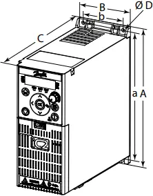
3.1 Mechanical Dimensions
|
Enclosure size |
Height [mm (in)] |
Width [mm (in)] |
Depth [mm (in)](2) |
Mounting holes |
e30bv012.10 |
|||
|
A |
A(1) | a | B | b | C | D | ||
| MA01c | 150 (5.9) | 216 (8.5) | 140.4 (5.5) | 70 (2.8) | 55 (2.2) | 143 (5.6) |
4.5 (0.18) |
|
|
MA02c |
176 (6.9) | 232.2 (9.1) | 150.5 (5.9) | 75 (3.0) | 59 (2.3) | 157 (6.2) | 4.5 (0.18) | |
| MA01a | 150 (5.9) | 202.5 (8.0) | 140.4 (5.5) | 70 (2.8) | 55 (2.2) | 158 (6.2) |
4.5 (0.18) |
|
|
MA02a |
186 (7.3) | 240 (9.4) | 176.4 (6.9) | 75 (3.0) | 59 (2.3) | 175 (6.9) | 4.5 (0.18) | |
| MA03a | 238.5 (9.4) | 291 (11.5) | 226 (8.9) | 90 (3.5) | 69 (2.7) | 200 (7.9) |
5.5 (0.22) |
|
|
MA04a |
292 (11.5) | 365.5 (14.4) | 272.4 (10.7) | 125 (4.9) | 97 (3.8) | 244.5 (9.6) | 7.0 (0.28) | |
| MA05a | 335 (13.2) | 396.5 (15.6) | 315 (12.4) | 165 (6.5) | 140 (5.5) | 248 (9.8) |
7.0 (0.28) |
|
Note: (1) Including decoupling plate. (2) The potentiometer on the local control panel extends 6.5 mm (0.26 in) from the drive.
3.2 Mounting Clearance
Table 1: Minimum Mounting Clearance
|
Enclosure size |
Minimum mounting clearance [maximum temperature 50 °C (122 °F)] |
| All enclosure sizes | Above and below: 100 mm (3.9 in). |
| MA01a–MA05a, MA02c | Sides: 0 mm (0 in). |
| MA01c (natural cooling) | Sides: 0 mm (0 in) for 40 °C (104 °F), 10 mm (0.39 in) and above for 50 °C (122 °F). |
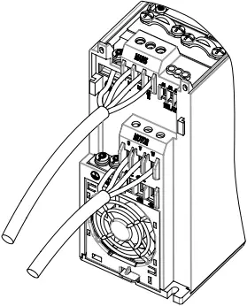
3.3 Connecting to Mains and Motor
- Mount the ground wires to the PE terminal.
- Connect motor to terminals U, V, and W.
- Mount mains supply to terminals L1/L, L2, and L3/N (3-phase) or L1/L and L3/N (single-phase) and tighten.
- For required maximum screwing torque, see the back of the terminal cover.
3.4 Load Sharing/Brake
Table 2: Connect Terminals
| Load sharing |
-UDC and +UDC/+BR |
| Brake |
-BR and +UDC/+BR |
- For MA01a, MA02a, and MA03a drives, wire with recommended connector (Ultra-Pod Fully Insulated FASTON Receptacles and Tabs, 521366-2, TE connectivity).
- For other enclosure sizes, mount the wires to the related terminal and tighten.
For required maximum screwing torque, see the back of the terminal cover. - For more details, contact Danfoss or refer to the drive’s design guide.
 e30bv011.10
Illustration 1: Mounting of Ground Cable, Mains, and Motor Wires
| NOTICE |
| Voltage levels of up to 850 V DC may occur between terminals +UDC/+BR and -UDC. Not short-circuit protected. |
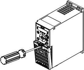
3.5 Control Terminals
- All control cable terminals are located underneath the terminal cover in front of the drive.
- See the back of the terminal cover for outlines of control terminals and switches.
| NOTICE |
| Remove the terminal cover with a screwdriver, see illustration 2. |
 e30bv009.10
Illustration 2: Removing Terminal Cover
e30bv010.10

Illustration 3: Overview of Control Terminals in PNP-configuration with Factory Setting (Speed Control Mode)
- Frequency output
- Reference
- Function: Fault
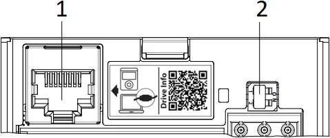
3.6 RJ45 Port and RS485 Termination Switch
The drive has an RJ45 port which complies with Modbus 485 protocol.
The RJ45 port is used for connecting:
- External control panel (Control Panel 2.0 OP2).
- PC tool (MyDrive® Insight) via an adapter option (Quick Adapter USB-C/RJ45 OAX00).
 e30bv050.11
Illustration 4: RJ45 Port and RS485 Termination Switch
- RJ45 port
- RS485 termination switch
(ON=RS485 terminated, OFF=Open)
| NOTICE |
| – The RJ45 port supports up to 3 m (9.8 ft) of shielded CAT5e cable which is NOT used to directly connect the drive to a PC. Failure to follow this notice causes damage to the PC. – If the drive is at the end of the fieldbus, set the RS485 termination switch to ON. – Do not operate RS485 termination switch when the drive is powered on. |
4 Programming
4.1 Control Panel
 e30bu992.10
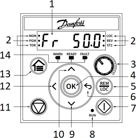
Illustration 5: Indicators and Operation Buttons
- Main display
- Status indicators
- Potentiometer
- OK
- Remote/Local
- Back
- Start
- Run indicator
- Down
- Up
- Stop/Reset
- Left
- Home/Menu
- Operating indicators
Table 3: Operation Buttons and Potentiometer
|
Name |
Function |
|
Home/Menu |
(1) Toggles between status display and main menu. (2) Long press to access the shortcut menu for quickly reading and editing parameters. |
|
Up/Down |
Switches status/parameter group/parameter numbers and tunes the parameter values. |
|
Left |
Moves the cursor 1 bit to the left. |
|
Back |
Navigates to the previous step in the menu structure or cancels the setting during tuning parameter values. |
|
OK |
Confirms the operation. |
|
Remote/Local |
Toggles between remote and local mode. |
|
Start |
Starts the drive in local mode. |
|
Stop/Reset |
Stops the drive in local mode, or resets the drive to clear a fault. |
|
Potentiometer |
Changes the reference value when the reference value is selected as potentiometer. |
Table 4: Status and Operating Indicator Lights
|
Name |
Function | |
| MON |
On |
Shows the drive status. |
| PGM | On | The drive is in programming status. |
|
TOR |
On |
The drive is in torque mode. |
|
Off |
The drive is in speed mode. | |
|
LOC |
On |
The drive is in local mode. |
|
Off |
The drive is in remote mode. | |
|
REV |
On |
The drive is in reverse direction. |
|
Off |
The drive is in forward direction. | |
|
ST2 |
Refer to Table 6 Multiple Setups Indicator Lights. | |
|
WARN |
Steadily lit when a warning occurs. | |
|
READY |
Steadily lit when the drive is ready. | |
|
FAULT |
Flashes when a fault occurs. | |
Table 5: Run Indicator Lights
|
Name |
Function | |
| RUN |
On |
The drive is in normal operation. |
|
Off |
The drive has stopped. | |
|
Flash |
In the motor-stopping process; or the drive received a RUN command, but no frequency output. | |
Table 6: Multiple Setups Indicator Lights
|
ST2 |
Off | On | Flash | Flash quickly |
| Active setup(1) | Setup 1 | Setup 2 | Setup 1 |
Setup 2 |
|
Programming setup(2) |
Setup 1 | Setup 2 | Setup 2 |
Setup 1 |
Note:
(1) Select active setup in parameter P6.6.1 Active Setup.
(2) Select programming setup in parameter P6.6.2 Programming Setup.
4.2 Operation with Control Panel
After the drive is powered up, press the Home/Menu button to toggle between status display and main menu. Use the Up/Down buttons to select items, and press the OK button to confirm selection.
e30bv048.11

Note: (1) Local mode only. (2) Remote mode only. (3) The status is only shown when the corresponding function is enabled.
(4) For AMA execution, refer to chapter Automatic Motor Adaptation (AMA). If parameter P5.4.3 Motor Control Principle is set as [0] U/f, no need to execute AMA.
Illustration 6: Operation with Control Panel
- Status Display
(MON status indicator light is on) - Main Menu
(PGM status indicator light is on) - Reference Setting (Hz)(1)
- Output Frequency (Hz)
- Motor Current (A)
- Torque (Nm)
- Udc Voltage (V)
- Power (kW)
- Reference (%)(2)
- Customer Readout (Unit)(3)
- Feedback (Unit)(2)(3)
- Quick Access
- All Parameters
- Events Information
- P4.2.1.1 Motor Type
- Q1: Motor Data
- *[0] IM Motor
- PM Motor
[1] SPM or [3] IPM - P4.2.2.1 Nominal Power
P4.2.2.2 Nominal Voltage
P4.2.2.3 Nominal Current
P4.2.2.4 Nominal Frequency
P4.2.2.5 Nominal Speed
P4.2.1.2 Number of Poles - P4.2.2.3 Nominal Current
P4.2.2.5 Nominal Speed
P4.2.3.7 Motor Cont. Rated Torque
P4.2.4.1 Back EMF
P4.2.1.2 Number of Poles - P4.2.1.3 AMA Mode(4)
- P5.4.1 Application Selection
- Q2: Application Selection
- *[20] Speed Control Mode
[21] Process Control Mode
[22] Multi Speed Control Mode
[23] 3-wire Control Mode
[24] Torque Control Mode - Q3: Motor Control
- P5.5.3.3 Reference Maximum
P5.5.3.4 Reference Minimum
P5.5.4.2 Ramp 1 Accel. Time
P5.5.4.3 Ramp 1 Decel. Time
P2.3.14 Max Output Frequency
P5.8.2 Motor Speed High Limit - Parameter group 1st level:
G1 Grid
G2 Power Conversion & DC-link
G3 Filters & Brake Chopper
G4 Motor
G5 Application
G6 Maintenance & Service
G8 Customization
G9 I/O
G10 Connectivity
4.3 Automatic Motor Adaptation (AMA)
- Via running AMA in VVC+ mode, the drive builds a mathematical model of the motor to optimize compatibility between drive and motor, and thus enhances the motor control performance.
- Some motors may be unable to run the complete version of the test. In that case, select [2] Enable Reduced AMA in parameter P4.2.1.3 AMA Mode.
- AMA completes within 5 minutes. For best results, run the following procedure on a cold motor.
Procedure:
- Set motor data according to the motor nameplate.
- If needed, set motor cable length in parameter P4.2.1.4 Motor Cable Length.
- Set [1] Enable Complete AMA or [2] Enable Reduced AMA for parameter P4.2.1.3 AMA Mode, the main display shows To start AMA, see illustration 7.
- Press the Start button, the test runs automatically and the main display indicates when it is completed.
- When AMA is completed, press any button to exit and return to normal operation mode.
e30bv055.10
![]()
To start AMA AMA is running AMA is completed
Illustration 7: AMA Status Indications
5 Troubleshooting
Table 7: Warning and Fault Events Summary
|
Number |
Description | Warning | Fault | Trip lock | Cause |
|
2 |
Live Zero Error |
X |
X |
– |
Signal on terminal 33 or 34 is less than 50% of the value set in parameter P9.5.2.3 T33 Low Voltage, parameter P9.5.2.5 T33 Low Current, parameter P9.5.3.3 T34 Low Voltage, and parameter P9.5.3.5 T34 Low Current. |
|
3 |
No Motor |
X |
X |
– |
No motor has been connected to the output of the drive. |
|
4 |
Mains Ph. Loss(1) |
X |
X |
X |
Missing phase on the supply side, or the voltage imbalance is too high. Check the supply voltage. |
|
7 |
DC overvol(1) |
X |
X |
– |
DC-link voltage exceeds the limit. |
|
8 |
DC undervolt(1) |
X |
X |
– |
DC-link voltage drops below the voltage warning low limit. |
|
9 |
Inverter Overld. |
X |
X |
– |
More than 100% load for too long. |
|
10 |
Motor ETR Overld. |
X |
X |
– |
Motor is too hot due to more than 100% load for too long. |
|
11 |
Motor Th. Overld. |
X |
X |
– |
Thermistor or thermistor connection is disconnected, or the motor is too hot. |
|
12 |
Torque Limit |
X |
X |
– |
Torque exceeds the value set in either parameter P5.10.1 Motor Torque Limit or parameter P5.10.2 Regenerative Torque Limit. |
|
13 |
Overcurrent |
X |
X |
X |
Inverter peak current limit is exceeded. If this fault occurs on power-up, check whether power cables are mistakenly connected to the motor terminals. |
|
14 |
Earth Fault |
X |
X |
X |
Discharge from output phases to ground. |
|
16 |
Short Circuit |
– |
X |
X |
Short circuit in motor or on motor terminals. |
|
17 |
Ctrl. Word TO |
X |
X |
– |
No communication to the drive. |
|
18 |
Start Failed |
– |
X |
– |
May be caused by a blocked motor. |
|
25 |
Brake Resistor Short |
– |
X |
X |
Brake resistor is short-circuited, thus the brake function is disconnected. |
|
26 |
Brake Overload |
X |
X |
– |
The power transmitted to the brake resistor over the last 120 s exceeds the limit. Possible corrections: Decrease brake energy via lower speed or longer ramp time. |
|
27 |
Brake IGBT/Brake chopper Short Circuited |
– |
X |
X |
Brake transistor is short-circuited, thus brake function is disconnected. |
|
28 |
Brake Check |
– |
X |
X |
Brake resistor is not connected/working. |
|
30 |
U phase loss |
– |
X |
X |
Motor phase U is missing. Check the phase. |
|
31 |
V phase loss |
– |
X |
X |
Motor phase V is missing. Check the phase. |
|
32 |
W phase loss |
– |
X |
X |
Motor phase W is missing. Check the phase. |
|
36 |
Mains Failure |
X |
X |
– |
This warning/fault is only active if the supply voltage to the drive is less than the value set in parameter P2.3.7 Power Loss Controller Limit, and parameter P2.3.6 Power Loss Action is NOT set to [0] No Function. |
|
38 |
Internal Fault |
– |
X |
X |
Contact the local supplier. |
|
40 |
Overload T15 |
X |
– |
– |
Check the load connected to terminal 15 or remove short-circuit connection. |
|
46 |
Gate drive Voltage Fault |
– |
X |
X |
– |
|
47 |
24 V Supply Low |
X |
X |
X |
24 V DC may be overloaded. |
|
50 |
AMA calibration failed |
– |
X |
– |
A calibration error has occurred. |
|
51 |
AMA Unom /Inom |
– |
X |
– |
Wrong setting for motor voltage and/or motor current. |
|
52 |
AMA low Inom |
– |
X |
– |
Motor current is too low. Check the settings. |
|
53 |
AMA big motor |
– |
X |
– |
The power size of the motor is too large for the AMA to operate. |
|
54 |
AMA small motor |
– |
X |
– |
The power size of the motor is too small for the AMA to operate. |
|
55 |
AMA par. range |
– |
X |
– |
The parameter values of the motor are outside of the acceptable range. AMA does not run. |
|
56 |
AMA interrupt |
– |
X |
– |
The AMA is interrupted. |
|
57 |
AMA timeout |
– |
X |
– |
– |
|
58 |
AMA internal |
– |
X |
– |
Contact the local supplier |
|
59 |
Current Limit |
X |
X |
– |
The drive is overloaded. |
|
60 |
External Interlock |
– |
X |
– |
External interlock has been activated. |
|
61 |
Feedback Error |
X |
X |
– |
– |
|
63 |
Mech. Brake Low |
– |
X |
– |
Actual motor current has not exceeded release brake current within start delay time window. |
|
69 |
Pwr. Card Temp |
X |
X |
X |
The cutout temperature of the power card has exceeded the upper limit. |
|
80 |
Drive Initialized |
– |
X |
– |
All parameter settings are initialized to default settings. |
|
87 |
Auto DC brake |
X |
– |
– |
Occurs in IT mains when the drive coasts, and the DC voltage is higher than 830 V for 400 V units and 425 V for 200 V units. The motor consumes energy on the DC link. This function can be enabled/disabled in parameter P2.3.13 Auto DC Braking. |
|
95 |
Lost load detected |
X |
X |
– |
– |
|
99 |
Locked Rotor |
– |
X |
– |
Rotor is blocked. |
|
126 |
Motor Rotating |
– |
X |
– |
PM motor is rotating when AMA is performed. |
|
127 |
Back EMF too High |
X |
– |
– |
The back EMF of PM motor is too high before starting. |
|
Err. 89 |
Read only |
– |
– |
– |
Parameters cannot be changed. |
|
Err. 95 |
Not while running |
– |
– |
– |
Parameters can only be changed when the motor is stopped. |
|
Err. 96 |
Password rejected |
– |
– |
– |
Occurs when using a wrong password for changing a password-protected parameter. |
Note: (1) These faults may be caused by mains distortions.
6 Specifications
Table 8: Mains Supply 1×100-120 V AC (Normal overload 150% for 1 minute)
| Frequency converter |
02A4 |
04A8 |
| Typical shaft output [kW (hp)] |
0.37 (0.5) |
1.1 (1.5) |
| Enclosure size |
MA01c |
MA02c |
| Output current | ||
| Continuous (3×200-240 V) [A] |
2.4 |
4.8 |
| Intermittent (3×200-240 V) [A] |
3.6 |
7.2 |
| Maximum cable size (Mains, motor) [mm²⁄AWG] |
4/10 |
|
| Maximum input current | ||
| Continuous (1×100-120 V) [A] |
11.6 |
25.6 |
| Intermittent (1×100-120 V) [A] |
17.4 |
38.4 |
| EMC filter type |
C4 |
|
Table 9: Mains Supply 1×200-240 V AC (Normal overload 150% for 1 minute)
| Frequency converter |
02A2 |
04A2 | 06A8 |
09A6 |
| Typical shaft output [kW (hp)] |
0.37 (0.5) |
0.75 (1.0) | 1.5 (2.0) |
2.2 (3.0) |
| Enclosure size |
MA01c |
MA01c | MA02c |
MA02a |
| Output current | ||||
| Continuous (3×200-240 V) [A] |
2.2 |
4.2 | 6.8 |
9.6 |
| Intermittent (3×200-240 V) [A] |
3.3 |
6.3 | 10.2 |
14.4 |
| Maximum cable size (Mains, motor) [mm²⁄AWG] |
4/10 |
|||
| Maximum input current | ||||
| Continuous (1×200-240 V) [A] |
6.1 |
11.6 | 18.7 |
26.4 |
| Intermittent (1×200-240 V) [A] |
8.3 |
15.6 | 26.4 |
37 |
| EMC filter type |
C1/C4 |
|||
Table 10: Mains Supply 3×200-240 V AC (Normal overload 150% for 1 minute)
| Frequency converter |
02A4 |
04A2 | 07A8 | 11A0 | 15A2 | 24A2 | 31A0 |
46A2 |
| Typical shaft output [kW (hp)] |
0.37 (0.5) |
0.75 (1.0) | 1.5 (2.0) | 2.2 (3.0) | 3.7 (5.0) | 5.5 (7.5) | 7.5 (10) |
11 (15) |
| Enclosure size |
MA01a |
MA01a | MA02a | MA03a | MA03a | MA04a | MA04a |
MA05a |
| Output current | ||||||||
| Continuous (3×200-240 V) [A] |
2.4 |
4.2 | 7.8 | 11.0 | 15.2 | 24.2 | 31.0 |
46.2 |
| Intermittent (3×200-240 V) [A] |
3.6 |
6.3 | 11.7 | 16.5 | 22.8 | 36.3 | 46.5 |
69.3 |
| Maximum cable size (Mains, motor) [mm²⁄AWG] |
4/10 |
16/6 |
||||||
| Maximum input current | ||||||||
| Continuous (3×200-240 V) [A] |
3.8 |
6.7 | 12.5 | 17.7 | 24.3 | 33.0 | 42.0 |
42.0 |
| Intermittent (3×200-240 V) [A] |
5.7 |
8.3 | 18.8 | 26.6 | 35.3 | 49.5 | 63.0 |
63.0 |
| EMC filter type |
C4 |
|||||||
Table 11: Mains Supply 3×380-480 V AC (Normal overload 150% for 1 minute
| Frequency converter |
01A2 |
02A2 | 03A7 | 05A3 | 07A2 |
09A0 |
| Typical shaft output [kW (hp)] |
0.37 (0.5) |
0.75 (1.0) | 1.5 (2.0) | 2.2 (3.0) | 3.0 (4.0) |
4.0 (5.5) |
| Enclosure size |
MA01a |
MA01a | MA01a | MA02a | MA02a |
MA02a |
| Output current | ||||||
| Continuous (3×380-440 V) [A] |
1.2 |
2.2 | 3.7 | 5.3 | 7.2 |
9.0 |
| Intermittent (3×380-440 V) [A] |
1.8 |
3.3 | 5.6 | 8.0 | 10.8 |
13.7 |
| Continuous (3×440-480 V) [A] |
1.1 |
2.1 | 3.4 | 4.8 | 6.3 |
8.2 |
| Intermittent (3×440-480 V) [A] |
1.7 |
3.2 | 5.1 | 7.2 | 9.5 |
12.3 |
| Maximum cable size (Mains, motor) [mm²⁄AWG] |
4/10 |
|||||
| Maximum input current | ||||||
| Continuous (3×380-440 V) [A] |
1.9 |
3.5 | 5.9 | 8.5 | 11.5 |
14.4 |
| Intermittent (3×380-440 V) [A] |
2.6 |
4.7 | 8.7 | 12.6 | 16.8 |
20.2 |
| Continuous (3×440-480 V) [A] |
1.7 |
3.0 | 5.1 | 7.3 | 9.9 |
12.4 |
| Intermittent (3×440-480 V) [A] |
2.3 |
4.0 | 7.5 | 10.8 | 14.4 |
17.5 |
| EMC filter type |
C2/C4 |
|||||
Table 12: Mains Supply 3×380-480 V AC (Normal overload 150% for 1 minute)
| Frequency converter |
12A0 |
15A5 | 23A0 | 31A0 | 37A0 |
43A0 |
| Typical shaft output [kW (hp)] |
5.5 (7.5) |
7.5 (10) | 11 (15) | 15 (20) | 18.5 (25) |
22 (30) |
| Enclosure size |
MA03a |
MA03a | MA04a | MA04a | MA05a |
MA05a |
| Output current | ||||||
| Continuous (3×380-440 V) [A] |
12 |
15.5 | 23 | 31 | 37 |
43 |
| Intermittent (3×380-440 V) [A] |
18 |
23.5 | 34.5 | 46.5 | 55.5 |
64.5 |
| Continuous (3×440-480 V) [A] |
11 |
14 | 21 | 27 | 34 |
40 |
| Intermittent (3×440-480 V) [A] |
16.5 |
21.3 | 31.5 | 40.5 | 51 |
60 |
| Maximum cable size (Mains, motor) [mm2⁄AWG] |
4/10 |
16/6 |
||||
| Maximum input current | ||||||
| Continuous (3×380-440 V) [A] |
19.2 |
24.8 | 33 | 42 | 34.7 |
41.2 |
| Intermittent (3×380-440 V) [A] |
27.4 |
36.3 | 47.5 | 60 | 49 |
57.6 |
| Continuous (3×440-480 V) [A] |
16.6 |
21.4 | 29 | 36 | 31.5 |
37.5 |
| Intermittent (3×440-480 V) [A] |
23.6 |
30.1 | 41 | 52 | 44 |
53 |
| EMC filter type |
C2/C4 |
|||||
7 Ambient Conditions
| Protection rating | IP20/Open Type (IP21/Type 1 conversion kit as an option). | |
| Temperature during operation | -20 °C to 55 °C (-4 °F to 131 °F), -10 °C to 50 °C (14 °F to 131 °F) without derating. | |
| Temperature during storage/transport | -25 °C to 65/70 °C (-13 °F to 149/158 °F). | |
| Relative humidity | 5-95%, non-condensing during operation. | |
| Altitude(1) | Without derating: 1000 m (3280 ft). With derating: 1000 m (3280 ft) to 4000 m (13123 ft), derate the output current by 1% for each 100 m (328 ft). | |
| Contamination level | Storage | IEC 60721-3-1, Class 1C2 (aggressive gases), Class 1S11 (dust/sand). |
| Transportation | IEC 60721-3-2, Class 2C2 (aggressive gases), Class 2S5 (dust/sand). | |
| Operation | IEC 60721-3-3, Class C4 (aggressive gases), Class 3S6 (dust/sand). | |
| Mechanical conditions | Storage | IEC 60721-3-1, Class 1M11. |
| Transportation | IEC 60721-3-2, Class 2M4. | |
| Operation | IEC 60721-3-3, Class 3M11. | |
Note: (1) Regarding IEC 61800-5-1 compliance, the default maximum altitude is 2000 m (6562 ft). When the installation site is at an altitude of 2000 m (6562 ft) to 4000 m (13123 ft), contact Danfoss for further information.
8 EMC Compatibility and Motor Cable Length
- Drive with built-in EMC filter fulfills radiated emission C2 limits.
- Drive with non built-in EMC filter fulfills conducted/radiated emission C4 requirements.
- The drive is designed to operate with optimum performance within the maximum motor cable lengths defined in Table 14 Maximum Motor Cable Length.
Table 13: EMC Compatibility Motor Cable Length
| Drive with built-in EMC filter |
Maximum motor cable length (shielded), @4kHz |
|
|
C1 (Conducted) |
C2 (Conducted) |
|
| 1×200-240 V AC |
5 m (16.4 ft) |
– |
| 3×400-480 V AC |
– |
15 m (49.2 ft) |
Table 14: Maximum Motor Cable Length
| Maximum motor cable length |
Shielded |
50 m (164 ft) |
|
Unshielded |
75 m (246 ft) |
9 Fuses and Circuit Breakers
|
iC2-Micro |
Non cabinet | Cabinet | |||||||
| UL fuse | CE fuse | UL circuit breaker | CE circuit breaker | Test cabinet size [Height x Width x Depth] [mm (in)] |
Minimum cabinet volume [L] |
||||
|
kW (hp) |
RK1 | T | J | CC | gG | ABB MS165 Maximum trip level | Eaton Maximum trip level | ||
| Standard fault current SCCR | 5 kA | 5 kA | 5 kA | 5 kA |
5 kA |
||||
|
High fault current SCCR |
– | 100 kA | – | 65 kA(1) |
– |
||||
| 1×100-120 V AC | |||||||||
|
0.37 (0.5) |
25 A | 25 A | 25 A | PKZM4-25 | 500 x 400 x 260 (19.7 x 15.7 x 10.2) |
52 | |||
| 1.1 (1.5) | 35 A | 50 A | 42 A |
PKZM4-50 |
|||||
| 1×200-240 V AC | |||||||||
|
0.37-0.75 (0.5-1.0) |
25 A | 25 A | 25 A | PKZM4-25 | 500 x 400 x 260 (19.7 x 15.7 x 10.2) |
52 | |||
| 1.5 (2.0) | 35 A | 35 A | 32 A |
PKZM4-32 |
|||||
|
2.2 (3.0) |
40 A | 50 A | 42 A | PKZM4-50 | |||||
| 3×200-240 V AC | |||||||||
| 0.37-0.75 (0.5-1.0) | 15 A | 16 A | 16 A | PKZM0-16 | 500 x 400 x 260 (19.7 x 15.7 x 10.2) |
52 |
|||
|
1.5 (2.0) |
30 A | 32 A | 32 A | PKZM4-32 | |||||
| 2.2-3.7 (3.0-5.0) | 40 A | 40 A | 42 A |
PKZM4-40 |
|||||
|
5.5-7.5 (7.5-10) |
60 A | 63 A | 65 A | PKZM4-63 | 800 x 400 x 300 (31.5 x 15.7 x 11.8) |
96 | |||
| 11 (15) | 60 A | 80 A | 80 A |
NZMN1-A80 |
|||||
| 3×380-480 V AC | |||||||||
|
0.37-1.5 (0.5-2.0) |
15 A | 16 A | 16 A | PKZM0-16 | 500 x 400 x 260 (19.7 x 15.7 x 10.2) |
52 | |||
| 2.2-4.0 (3.0-5.5) | 30 A | 40 A | 32 A |
PKZM4-32 |
|||||
|
5.5-7.5 (7.5-10) |
40 A | 40 A | 42 A | PKZM4-40 | |||||
| 11-15 (15-20) | 60 A | 63 A | 65 A | PKZM4-63 | 800 x 400 x 300 (31.5 x 15.7 x 11.8) |
96 |
|||
|
18.5-22 (25-30) |
60 A | 80 A | 80 A |
NZMN1-A80 |
|||||
Note: (1) The power ratings of iC2-Micro Frequency Converters up to 15 kW (20 hp) are 65 kA when protected by Type E CMC, 18.5 kW (25 hp) and 22 kW (30 hp) are 50 kA when protected by Type E CMC.

10 Technical Documentation
Scan the QR code to access more technical documents for the drive. Or, after scanning the QR code, click Global English on the website to select your local region’s website, search iC2 to find the documents with your own languages.
Danfoss A/S
Ulsnaes 1
DK-6300 Graasten
drives.danfoss.com
Danfoss can accept no responsibility for possible errors in catalogs, brochures, and other printed material.
Danfoss reserves the right to alter its products without notice. This also applies to products already on order provided that such alterations can be made without subsequential changes being necessary in specifications already agreed. All trademarks in this material are property of the respective companies.
Danfoss and the Danfoss logotype are trademarks of Danfoss A/S. All rights reserved.
Danfoss A/S © 2024.06
AQ379331704297en-000501 / 130R1215
Documents / Resources
 |
Danfoss 130R1215 iC2-Micro Frequency Converters [pdf] Installation Guide 130R1215, 130R1215 iC2-Micro Frequency Converters, iC2-Micro Frequency Converters, Frequency Converters, Converters |


