DALCNET DLM12XX-1CV DLM Single Channel Multi-Input
FEATURES
- FADER+DIMMER+DRIVER
- DC Input: 12-24-48 Vdc or 12-24 Vdc
- MULTI INPUT – Analogic Automatic Detection of the Local command:
- Normally Open push-button
- Analog input 0-10V
- Analog input 1-10V
- Potentiometer 10KOhm
- PUSH MENU’ – Possibility to set:
- The minimum value of dimming
- Fade In
- Fade Out
- Constant Voltage variant for Common Anode applications
- Voltage outputs for R-L-C loads, DLM1248-1CV variant
- Voltage outputs for R loads, DLM1224-1CV variant
- Memory function
- Adjusting the brightness of white light or monochromatic color
- Adjusting the brightness up to complete off
- Soft start and soft stop
- Sync function – Master/Slave
- Optimized output curve
- Typical efficiency > 95%
- 100% Functional test – 5 Years warranty
For the whole and updated Device, Manual refer to the producer’s website: http://www.dalcnet.com
CONSTANT VOLTAGE VARIANTS
| CODE | Input voltage | Output | Channels | Analogic Auto Detection | |
|
DLM1248-1CV |
12-48V DC |
1 x 6,5A |
1 |
N° 1 N.O. Push Button N° 1 analog signal 0-10V N° 1 analog signal 1-10V
N° 1 Potentiometer 10K |
|
|
DLM1224-1CV |
12-24V DC |
1 x 10A |
1 |
N° 1 N.O. Push Button N° 1 analog signal 0-10V N° 1 analog signal 1-10V
N° 1 Potentiometer 10K |
Application: Dimmer
The LED dimmer is produced by default with:
- Analogic Automatic Detection of local command set as N.O. Push Button
- Dimming minimum level 1%
PROTECTIONS
| DLM1248-1CV | DLM1224-1CV | ||
| OTP | Over temperature protection1 | | |
| OVP | Over voltage protection2 | | |
| UVP | Under voltage protection2 | | |
| RVP | Reverse polarity protection2 | | |
| IFP | Input fuse protection2 | | |
| SCP | Short circuit protection | | |
| OCP | Open circuit protection | | |
| CLP | Current limit protection | | |
| EN 61347-1 | Lamp controlgear – Part 1: General and safety requirements |
| EN 55015 | Limits and methods of measurement of radio disturbance characteristics of electrical lighting and similar equipment |
| EN 61547 | Equipment for general lighting purposes – EMC immunity requirements |
| IEC 60929-E.2.1 | Control interface for controllable ballasts – control by d.c. voltage – functional specification |
| ANSI E 1.3 | Entertainment Technology – Lighting Control Systems – 0 to 10V Analog Control Specification |
TECHNICAL SPECIFICATIONS
| DLM1248-1CV Variant | DLM1224-1CV Variant | ||
| Constant voltage | Constant voltage | ||
| Supply voltage | min: 10,8 Vdc .. max: 52,8 Vdc | min: 10,8 Vdc .. max: 26,4 Vdc | |
| Output voltage | = Vin | = Vin | |
| Input current | max 6,5A | max 10A | |
| Output current | 6,5A 3 | 10A 3 | |
| Absorbed nominal power3 | @12V | 78 W | 120 W |
| @24V | 156 W | 240 W | |
| @48V | 312 W | – | |
| Power loss in standby mode | <500mW | <500mW | |
| Type of Load | R – L – C | R | |
| Thermal shutdown4 | 150°C | – | |
| Command supply current | 0,5mA (per 1-10V) | 0,5mA (per 1-10V) | |
| Command required current (max) | 0,1mA (per 0-10V) | 0,1mA (per 0-10V) | |
| D-PWM dimming frequency | 300Hz | 300Hz | |
| D-PWM resolution | 16 bit | 16 bit | |
| D-PWM range | 0,1 – 100% | 0,1 – 100% | |
| Storage Temperature | min: -40 max: +60 °C | min: -40 max: +60 °C | |
| Ambient Temperature | min: -10 max: +40 °C | min: -10 max: +40 °C | |
| Wiring | 2.5mm2 solid – 2.5mm2 stranded – 30/12 AWG | 1.5mm2 solid – 1mm2 stranded – 30/16 AWG | |
| Wire preparation length | 5.5 – 6.5 mm | 5 – 6 mm | |
| Protection grade | IP20 | IP20 | |
| Casing material | Plastic | Plastic | |
| Packaging unit (pieces/unit) | Single Carton Box 1 pz | Carton Box 10pz | |
| Mechanical dimensions | 44 x 57 x 25 mm | 44 x 57 x 19 mm | |
| Package dimensions | 56 x 68 x 35 mm | 164 x 117x 70 mm | |
| Weight | 40g | 306g | |
- Maximum value, dependent on the ventilation conditions. This value is measured at 40°C, it is maximum ambient temperature.
- Thermal Protection on the output channel in case of high temperature. The thermal intervention is detected by transistor.
INSTALLATION
To set the product, follow the instruction on the picture below:
- connect the power supply (12-24 Vdc or 12-48 Vdc depending on the dimmer model) to terminal blocks “DC IN” of the device.
- connect the LOCAL COMMAND to the terminal blocks “INPUT” of the device.
- connect the LED in the output terminal blocks “OUT” of the device.

LOCAL COMMAND
AUTOMATIC DETECTION OF THE TYPE OF LOCAL COMMAND
At the first switch, the device is set by default to automatic recognition of push button N.O. Command.
AUTOMATIC DETECTION OF THE 0/1-10V & POTENTIOMETER COMMAND
The automatic recognition of analog signal 0/1-10V or potentiometer starts as a 0/1-10V value between 3V and 7V is sent out or setting the potentiometer with a value included from 30% and 70%.
| COMMAND 0-10V | COMMAND 1-10V | POTENTIOMETER |
AUTOMATIC DETECTION OF THE N.O. PUSH BUTTON COMMAND
The N.O. push button s identified automatically after 5 clicks in rapid sequence. In mode N.O. push button, function memory is always active.
SYNC INSTALLATION
SYNC FUNCTION WITH SINGLE POWER SUPPLY
It is possible to connect multiple device of the family DLM-1CV among them in mode Master/Slave
Connect the local command desired to the device used as Master. Connect master “TX” signal to the “RX” entrances of slave. Example of Master/Slave:
SYNC FUNCTION WITH ONE POWER SUPPLY FOR DIMMER
In the case multiple power supplies are used to power “master” dimmer and “slave” dimmers, connect all the “COM” inputs of the LedDimmer to each other.
SYNC FUNCTION WITH ONE POWER SUPPLY FOR DIMMER
In the case multiple power supplies are used to power “master” dimmer and “slave” dimmers, connect all the “COM” inputs of the LedDimmer to each other.
NOTE FOR MASTER/SLAVE INSTALLATION
- Using one power supply every single dimmer, first power on the Master unit and after that give power to the Slave.
- When doing maintenance on the installation take care of shutting down power to the Slave units first and than to the Master.
- When power to the Master unit is missing, the Slave set up automatically to the default ex-factory settings (power on 100%) or to the settings previously saved.
TECHNICAL NOTE
Installation:
- Installation and maintenance must be performed only by qualified personnel in compliance with current regulations.
- The product must be installed inside an electrical panel protected against overvoltages.
- The product must be installed in a vertical or horizontal position with the cover / label upwards or vertically; Other positions are not permitted. It is not permitted to bottom-up position (with the cover / label down).
- Keep separated the circuits at 230V (LV) and the circuits not SELV from circuits to low voltage (SELV) and from any connection with this product. It is absolutely forbidden to connect, for any reason whatsoever, directly or indirectly, the 230V mains voltage to the bus or to other parts of the circuit.
Power supply:
- For the power supply use only a SELV power supplies with limited current, short circuit protection and the power must be dimensioned correctly. In case of using power supply with ground terminals, all points of the protective earth (PE = Protection Earth) must be connected to a valid and certified protection earth.
- The connection cables between the power source “low voltage” and the product must be dimensioned correctly and they should be isolated from every wiring or parts at voltage not SELV. Use double insulated cables.
- Dimension the power supply for the load connected to the device. If the power supply is oversized compared with the maximum absorbed current, insert a protection against over-current between the power supply and the device.
Command:
- The length of the connection cables between the local commands (N.O. Push button, 0-10V, 1-10V, Potentiometer or other) and the product must be less than 10m; the cables must be dimensioned correctly and they should be isolated from every wiring or parts at voltage not SELV. Use double insulated shielded and twisted cables.
- The length and type of the connection cables at the BUS SYNC must be less than 3m and they should be isolated from every wiring or parts at voltage not SELV. It is suggested to use double insulated shielded and twisted cables.
- All the product and the control signal connect at the bus and at the local command (N.O. Push button, 0-10V, 1-10V, Potentiometer or other) must be SELV (the devices connected must be SELV or supply a SELV signal)
Outputs:
The length of the connection cables between the product and the LED module must be less than 10m; the cables must be dimensioned correctly and they should be isolated from every wiring or parts at a voltage, not SELV. Is preferable to use shielded and twisted cables.
MECHANICAL DIMENSION
PUSH DIMMER FEATURE
| Button | Intensity |
| Click | On/Off |
| Double Click | Maximum intensity |
| Long pressure (>1s) from OFF | Turn ON at 1% (Nightly Time), then dimmer up/down |
| Long pressure (>1s) from ON | Dimmer up/down |
| 15 Click in 5 second-time | Enter in to PUSH MENU’ |
The intensity and the status change (ON/OFF) are controlled by the N.O. push button.
0-10V & 1-10V & POTENTIOMETER FEATURE
| Button | Function | Intensity |
| 0-10V
1-10V Potentiometer 10K |
Dimmer: 0-1V=0% 10V=100% |
The intensity is controlled by input voltage variation.
PUSH MENU
FUNCTION AVAILABLE
- MINIMUM VALUE OF DIMMING
- POWER-ON RAMP (FADE IN)
- POWER-OFF RAMP (FADE OUT)
ACCESS TO MENU’
When you turn-on the LED dimmer, the output is set at 100% and the minimum of dimming is at 1 %. To access the device menu, click the push button 15 times in 5 seconds time.
When the Load flashes, you are in “MENU’ 1”.
MENU’ 1 – MINIMUM VALUE OF DIMMING
Every single click make it changing the minimum value of dimming There are six level of minimum: 0,1%, 1%, 5%, 10%, 20%, 30% and 100% After setting the minimum value of dimming press long to confirm. A double flashing confirms the storage and you can go to “MENU’ 2”
Note: if you set the minimum level to 100%, once the settings is confirmed, the device automatically exits the MENU’.
MENU 2 – POWER-ON RAMP (FADE IN)
Every single click make it changing the power-on ramp There are five levels of power-on ramp (FADE IN): Instantaneous, 1 second, 2 seconds, 3 seconds, 6 seconds. After setting the FADE IN press a long to confirm. Three flashes confirm the storage and you can go to “MENU’ 3”
MENU’ 3 – POWER-OFF RAMP (FADE OUT)
Every single click make it change the power-off ramp There are five levels of power-off ramp (FADE OUT): Instantaneous, 1 second, 2 seconds, 3 seconds, 6 seconds. After setting the FADE OUT press long to confirm. Three quick flashes confirm the storage and you go out from the “DEVICE MENU’” When you are out of the Menu’, the Lamp which is connected to the LED Dimmer turns on at the minimum level of dimming previously set.
DALI BUS SETUP
In DALI BUS SETUP all the leds are controlled by an external DALI controller.
BUS CONNECTION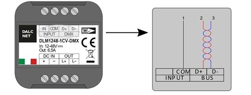
COMMAND
| STANDARD COMMAND | |
| DIRECT ARC POWER | ü |
| OFF | ü |
| UP | ü |
| DOWN | ü |
| STEP UP | ü |
| STEP DOWN | ü |
| RECALL MAX LEVEL | ü |
| RECALL MIN LEVEL | ü |
| STEP DOWN AND OFF | ü |
| ON AND STEP UP | ü |
| GOTO SCENE (0 to 15) | ü |
| RESET | ü |
| STORE ACTUAL LEVEL IN THE DTR | ü |
| STORE THE DTR AS MAX LEVEL | ü |
| STORE THE DTR AS MIN LEVEL | ü |
| STORE THE DTR AS SYSTEM FAILURE LEVEL | ü |
| STORE THE DTR AS POWER ON LEVEL | ü |
| STORE THE DTR AS FADE TIME | ü |
| STORE THE DTR AS FADE RATE | ü |
| STORE THE DTR AS SCENE (0 to 15) | ü |
| REMOVE FROM SCENE (0 to 15) | ü |
| ADD TO GROUP (0 to 15) | ü |
| REMOVE FROM GROUP (0 to 15) | ü |
| STORE DTR AS SHORT ADRESS | ü |
| ENABLE WRITE MEMORY | û |
| QUERY STATUS | 5 |
| QUERY BALLAST | ü |
| QUERY LAMP FAILURE | 5 |
| QUERY LAMP POWER ON | ü |
| QUERY LIMIT ERROR | ü |
| QUERY RESET STATE | ü |
| QUERY MISSING SHORT ADDRESS | ü |
| QUERY VERSION NUMBER | ü |
| QUERY CONTENT DTR | ü |
| QUERY DEVICE TYPE | 6 |
| QUERY PHYSICAL MINIMUM LEVEL | ü |
| QUERY POWER FAILURE | ü |
| QUERY CONTENT DTR1 | ü |
| QUERY CONTENT DTR2 | ü |
| QUERY ACTUAL LEVEL | ü |
| QUERY MAX LEVEL | ü |
| QUERY MIN LEVEL | ü |
| QUERY SYSTEM FAILURE LEVEL | ü |
| QUERY FADE TIME / FADE RATE | ü |
| QUERY SCENE LEVEL (0 to 15) | ü |
| QUERY GROUPS 0-7 | ü |
| QUERY GROUPS 8-15 | ü |
| QUERY ADDRESS H | ü |
| QUERY ADDRESS M | ü |
| QUERY ADDRESS L | û |
| READ MEMORY LOCATION | û |
| SPECIAL COMMAND | |
| TERMINATE | ü |
| DATA TRANSFERT REGISTER | ü |
| INITIALIZE | ü |
| RANDOMIZE | ü |
| COMPARE | ü |
| WITHDRAW | ü |
| SEARCHADOR H | ü |
| SEARCHADOR M | ü |
| SEARCHADOR L | ü |
| PROGRAM SHORT ADDRESS | ü |
| VERIFY SHORT ADDRESS | ü |
| QUERY SHORT ADDRESS | ü |
| PHYSICAL SELECTION | û |
| ENABLE DEVICE TYPE | û |
| DATA TRANSFER REGISTER 1 | ü |
| DATA TRANSFER REGISTER 2 | ü |
| WRITE MEMORY LOCATION | û |
DEFAULT VALUE
| FACTORY | RESET | |
| ACTUAL LEVEL | 254 | 254 |
| POWER ON LEVEL | 254 | 254 |
| SYSTEM FAILURE LEVEL | 254 | 254 |
| MIN LEVEL | 1 | 1 |
| MAX LEVEL | 254 | 254 |
| FADE RATE | 7 | 7 |
| FADE TIME | 0 | 0 |
| SHORT ADDRESS | FF | (no change) |
| SEARCH ADDRESS | FF FF FF | FF FF FF |
| RANDOM ADDRESS | FF FF FF | FF FF FF |
| GROUP 0-7 | 0 | 0 |
| GROUP 8-15 | 0 | 0 |
| SCENE 0-15 | MASK | MASK |
| STATUS INFORMATION | 1??0???? | 0?100??? |
| VERSION NUMBER | 1 | (no change) |
| PHYSICAL MIN. LEVEL | 1 | (no change) |
| ANSI E1.11 | Entertainment Technology – USITT DMX512-A – Asynchronous Serial Digital Data Transmission Standard for
Controlling Lighting Equipment and Accessories |
| ANSI E1.20 | Entertainment Technology-RDM-Remote Device Management over USITT DMX512 Networks |
CHANNEL MAPS
| Channel | Function | Value |
| 1 | Dimmer | Intensity [0..255] |
RDM COMMAND
| REQUESTED PARAMETERS | |
| DISC_UNIQUE_BRANCH | ü |
| DISC_UN_MUTE | ü |
| SUPPORTED_PARAMETERS | ü |
| PARAMETERS_DESCRIPTION | ü |
| DEVICE_INFO | ü |
| SOFTWARE_VERSION_LABEL | ü |
| DMX_START_ADDRESS | ü |
| IDENTIFY_DEVICE | ü |
| SUPPORTED PARAMETERS | |
| PRODUCT_DETAIL_ID_LIST | ü |
| DEVICE_MODEL_DESCRIPTION | ü |
| MANUFACTURER_LABEL | ü |
| DEVIDE_LABEL | ü |
| BOOT_SOFTWARE_VERSION_ID | ü |
| BOOT_SOFTWARE_VERSION_LABEL | ü |
| DMX_PERSONALITY | ü |
| DMX_PERSONALITY_DESCRIPTION | ü |
| SLOT_INFO | ü |
| SLOT_DESCRIPTION | ü |
| DEFAULT_SLOT_VALUE | ü |
Documents / Resources
 |
DALC NET DLM12XX DLM Single Channel Device [pdf] Instruction Manual DLM12XX, DLM Single Channel Device |


