![]() VIBRATION ANALYSIS HARDWARE
VIBRATION ANALYSIS HARDWARE

LP802 Series
Product Manual
Introduction
4-20 mA Vibration Monitoring Process Overview
4-20 mA technology can be used to measure temperature, pressure, flow and speed, as well as the overall vibration of rotating machines . Adding a vibration sensor/transmitter to the machine provides a critical measure of the machine’s health . It can be used to dentify changes in balance, alignment, gears, bearings, and many other potential faults . The purpose of the 4-20 mA analog current loop is to transmit the signal from an analog vibration sensor over a distance in the form of a 4-20 mA current signal . The current signal generated is proportional to the overall vibration of the equipment or machinery that is being monitored . This output current has a range of 4-20 mA, with 4 representing the minimum and 20 representing maximum amplitudes (within the range of 4-20 mA) . The 4-20 mA signal output is proportional to the overall amplitude generated within a defined frequency band . Therefore, the signal does not include data from frequencies outside the frequency band but includes all vibration (critical and non-critical faults) within that band .
LP802 Series Overview
Each LP802 sensor that is approved for Intrinsic Safety must meet or exceed the requirements for standards recognized by the countries that would use the sensors .
Specific Conditions of Use:
Specific ambient conditions of use include -40°F to 176°F (-40°C to 80°C) for all LP Series
Special Conditions for Safe Use:
None
Intrinsically Safe Information
Compliance with the Essential Health and Safety Requirements
Assured by compliance with EN60079-0:2004, EN60079-11:2007, EN6007926:2007, EN61241-0:2006, EN61241-11:2007
ATEX Related Nameplate Markings
The following is a complete recapitulation of ATEX nameplate markings so the customer has complete ATEX information for specific conditions of use .
![]()
INTRINSICALLY SAFE
SECURITE INTRINSEQUE
Ex ia IIC T3 / T4
Ex iaD A20 T150 °C (T-Code = T3) / T105 °C (T-Code = T4)
DIP A20 IP6X T150 °C (T-Code = T3) / T105 °C (T-Code = T4)
AEx ia IIC T3 / T4
AEx iaD 20 T150 °C (T-Code = T3) / T105 °C (T-Code = T4)
CLI GPS A,B,C,D
CLII, GPS E,F,G, CLIII
CLI, ZONE 0, ZONE 20
OPERATING TEMP CODE: T4
AMBIENT TEMP RANGE = -40 °C TO +80 °C
CONTROL DRAWING INS10012
Ex ia IIC T3 -54 °C < Ta < +125 °C
Ex ia IIC T4 -40 °C < Ta < +80 °C
Ui=28Vdc Ii=100mA
Ci=70nF Li=51µH Pi=1W
CSA 221421
KEMA 04ATEX1066
LP80*, and LP90* Series – Temperature Code: T4
Ambient temperature range = -40 °C to 80 °C
Product Specifications
| Power Input | 15-30 Vdc supply voltage required |
| Band-Pass Filter | The vibration sensor contains a band-pass filter, consisting of a low-pass and a high-pass . |
| Analog Output | Full-scale output of 4-20 mA |
| Operation | Filters the signal, and normalizes the output to the specified full-scale output . Performs a true RMS conversion and transmits this data in a 4-20 mA format (if RMS is chosen) . |
| Temperature Range | -40°F to 176°F (-40°C to 80°C) |
Dimension Drawings

Wiring
The Intrinsic Safety Control Drawing INS10012 below shows the installation requirements for CTC IS Sensors . As shown, properly installed barriers are required to limit the energy the sensor can receive . Cabling brings the signal from the sensor to the Zener diode barrier or galvanic isolator, which is the energy-limiting interface . The signal is transferred through the barrier (which can be located in a Class I Div 2 or non-hazardous area) to measurement equipment, such as a data collector or junction box, for further processing .

NOTES:
- Unspecified barrier strip shown
- See safety barrier manufacturer installation manual for information on proper wiring of sensor cables to the terminal blocks of the safety barrier
- Wire color for clarity only
Loop Resistance Calculations
Standard Loop
Powered Sensors
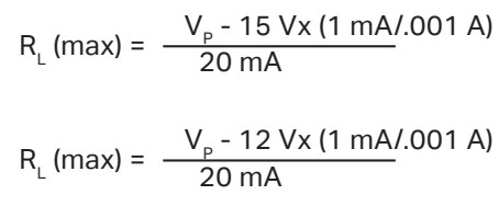
*Instrinsically Safe Loop Powered Sensors
*Note: Typical Loop Powered Circuit will include an Intrinsically Safe Barrier in the Circuit
| Power Source Voltage (Vp) | Typical RL (max) (Non-IS Sensors) |
Typical RL (max) (IS Sensors) |
| 20 | 250 | 100 |
| 24 | 450 | 300 |
| 26 | 550 | 400 |
| 30 | 750 | 600 |
Measurement
| FULL-SCALE MEASUREMENT RANGE |
ACTUAL VIBRATION, IPS |
EXPECTED OUTPUT (mA) |
| 0 – 0.4 IPS (0 – 10 mm/s) | 0 | 4 |
| 0.1 (2.5 mm/s) | 8 | |
| 0.2(5.0 mm/s) | 12 | |
| 0.3 (7.5 mm/s) | 16 | |
| 0.4 (10.0 mm/s) | 20 | |
| 0 – 0.5 IPS | 0 | 4 |
| 0.1 | 7. | |
| 0.2 | 10. | |
| 0.3 | 14. | |
| 0.4 | 17. | |
| 0.5 | 20 | |
| 0- 0.8 IPS (0 – 20 mm/s) | 0 | 4 |
| 0.2 (5.0 mm/s) | 8 | |
| 0.4 (10.0 mm/s) | 12 | |
| 0.6 (15.0 mm/s) | 16 | |
| 0.8 (20.0 mm/s) | 20 | |
| 0 -1.0 IPS (LP800 Series) | 0 | 4 |
| 0.1 | 6. | |
| 0.25 | 8 | |
| 0.5 | 12 | |
| 0.75 | 16 | |
| 1 | 20 | |
| 0 – 2.0 IPS (LP800 Series) | 0 | 4 |
| 0.25 | 6 | |
| 0.5 | 8 | |
| 0.75 | 10 | |
| 1 | 12 | |
| 1. | 14 | |
| 2. | 16 | |
| 135 | 18 | |
| 2 | 20 |
Installation
Tighten the sensor to the mounting disk using 2 to 5 ft-lbs of mounting force.

– The mounting torque is important to the frequency response of the sensor for the following reasons:
- If the sensor is not tight enough, proper coupling between the base of the sensor and the mounting disk will not be achieved .
- If the sensor is over tightened, stud failure may occur .
– A coupling agent (such as MH109-3D epoxy) will maximize the high frequency response of your hardware, but is not required .
Permanent/Stud Mounting Surface Preparation
- Prepare flat surface using a spot face tool and pilot drill hole using a CTC spot face installation tool .
- The mounting surface should be clean and free from any residue or paint .
- Tap for required thread ( ¼-28 or M6x1) .
- Install sensor .
– Suggested Installation Tool Kit: MH117-1B
Warranty and Refund
Warranty
All CTC products are backed by our unconditional lifetime warranty . If any CTC product should ever fail, we will repair or replace it at no charge .
Refund
All stock products can be returned for a 25% restocking fee if returned in new condition within 90 days of shipment . Stock products qualify for free cancellation if your order is cancelled within 24 hours of purchase . Built-to-order products qualify for a 50% refund if returned in new condition within 90 days of shipment . Custom products are quoted and built specifically to the requirements of the customer, which may include completely custom product designs or private labeled versions of standard products for OEM customers . Custom products ordered are non-cancellable, non-returnable and non-refundable .
![]()
Mm-Lp802/Rev B
Documents / Resources
 |
CTC LP802 Intrinsic Safety Loop Power Sensors [pdf] Owner's Manual LP802 Intrinsic Safety Loop Power Sensors, LP802, Intrinsic Safety Loop Power Sensors, Safety Loop Power Sensors, Loop Power Sensors, Power Sensors, Sensors |