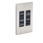
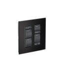
CSI Controls RK Series Control Panel Transmitter Models
 Parts included
WARNING!
ELECTRICAL SHOCK HAZARD
Disconnect all power sources before servicing. Failure to do so could result in serious injury or death.
This control panel must be installed and serviced by a licensed electrician in accordance with the National Electric Code NFPA-70, state and local electrical codes.
UL Type 4X enclosures are for indoor or outdoor use.
Warranty void if panel is modified.
CSI Controls® offers a five-year limited warranty on most standard catalog products. For complete terms and conditions, please visit www.csicontrols.com.
Products returned must be cleaned, sanitized, or decontaminated as necessary prior to shipment to ensure that employees will not be exposed to health hazards in handling said material. All applicable laws and regulations shall apply.
For technical support:
email: techsupport@sjeinc.com
phone: +1-800-746-6287
www.csicontrols.com
Installing the Transmitter and Float Switches
The RK Series™ Single Phase control panel operates with one 4-20mA submersible level transmitter and one or two backup fl oat switches.
- WARNING:
Ensure all power is turned OFF before installing fl oats in tank. Failure to do so could result in serious or fatal shock.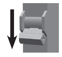
- CAUTION!
If the fl oats are not properly mounted and connected in the correct order, the pumps will not function properly.
Floats require free range of motion.
WARNING: To prevent erroneous measurements, do not allow the sensor diaphragm to come into contact with solid objects or sludge. Do not use level measurements less than 4” (10.2 cm) for control or alarm purposes (dead band).
Caution: Do not overtighten clamp or tie straps. - 2-Float & Transmitter Installation

Mounting the Control Panel
Mount control panel using integrated mounting flange.
NOTE
If the distance to the control panel exceeds the length of the fl oat switch cords or the pump power cord, splicing in a liquid-tight junction box will be required. For outdoor or wet installation, we recommend a UL Type 4X junction box.
Wiring the Control Panel
- Determine conduit entrance locations on control panel as shown. Check local codes and wiring diagram on the inside cover of the panel for the number of power circuits required.
CAUTION! Be sure the pump power voltage and phase are the same as the pump motor being installed.
Use of separate pump and control/alarm power sources is recommended. - Connect the following wires to the proper terminal positions:
- incoming power for each pump circuit
- incoming power for control/alarm circuit
- pump 1
- pump 2 (Duplex)
- backup fl oat switches
- 4-20mA transmitter
CAUTION! You must use conduit sealant to prevent moisture or gases from entering the panel.
Type 4X conduit must be used to maintain a Type 4X rating of the control panel.
- Verify correct operation of control panel after installation is complete.
Operations
This RK Series™ control panel uses a 4-20mA level transmitter.
Hand Operation – If the level is above the “Pump Off Setpnt” and the Low level back up Float Switch is UP, press the “HAND” switch momentarily and the pump will run until the level drops below the “Pump Off Setpnt” or the fl oat opens, or press the “HAND” switch again to stop the pump. For Time dose operation, the HAND pump operation is limited by the “Pump On Time”.
Press and hold the “HAND” switch to operate the pump if the Low Level Backup fl oat is OPEN or the level is below the “Pump Off Setpnt”.
Off Operation – Turn corresponding breaker off to be in Off operation.
Auto Operation – In timed dose mode, the timer controls the pump ON and OFF time as long as the well level is above the “Lead ON Setpoint” and the Low Level backup fl oat is CLOSED. If the level drops below the “Off Setpoint”, the timer will stop the pump and end the dose prematurely.
In demand mode, the level transmitter controls the pumps. The lead pump will start when the level rises above the “Lead ON Setpoint” and run until the level drops below “Off Setpoint”.
Power and Blown Fuse Indicators
The Control and Alarm circuits each have a green LED indicator when power is applied.
If a fuse is blown, the red fuse blown LED indicator above the fuse will turn ON.
Controller Navigation and Setup
Viewing or Changing Parameters:
- Press the Menu/Enter button to advance to the next menu.
- Press and hold the Menu/Enter button for 3 seconds to access setting Menus.
- Press Set/Change button to access Setting Menus and to edit/view parameters/function.
- After 60 seconds of no activity in the Settings Menu the controller will go back to Main Display Menus.
Screen Navigation (Duplex Demand) – Complete Navigation found on the back of this Manual. ![]()
Editing Parameters
Example: Changing the Pump Off Setpoint from 10.0 inches to 12.5 inches. ![]()
Parameters
| Level Cntrl Menu | Default Value | Min | Max | User |
| Lead Pump Set | Alternate | Alternate, Pump 1 is Lead, Pump 2 is Lead | ||
| Low Level Alarm | Light Only | Alarm Off, Light Only, Light & Audible | ||
| Reset Cyc Cnt #1 | Do Not Reset | Do Not Reset, Reset Counter | ||
| Reset Cyc Cnt #2 | Do Not Reset | Do Not Reset, Reset Counter | ||
| Reset E.T.M. #1 | Do Not Reset | Do Not Reset, Reset Counter | ||
| Reset E.T.M. #2 | Do Not Reset | Do Not Reset, Reset Counter | ||
| Reset HL Counter | Do Not Reset | Do Not Reset, Reset Counter | ||
| Reset Ovrd. Cnt. | Do Not Reset | Do Not Reset, Reset Counter | ||
| Transmtr. Range | 100.5 inches | 1.0 inches | 999.9 inches | |
| Transmtr. Offset | 000.0 inches | 0.0 inches | 999.9 inches | |
| Units | Inches | Inches, Feet, Meters, Centimeters | ||
| Backup Run Time | 00:30 (MM:SS) | 00:00 | 99:59 | |
| Time Dosing Menu | Default Value | Min | Max | User |
| Pump 1 Time On | 01:00 (MM:SS) | 00:01 | 99:59 | |
| Pump 1 Time Off | 00:00 (HH:MM) | 00:01 (00:00=demand operation) | 99:59 | |
| Pump 1 Ovrrid On | 02:00 (MM:SS) | 00:01 | 99:59 | |
| Pmp 1 Ovrrid Off | 06:00 (HH:MM) | 00:01 | 99:59 | |
| Pump 2 Time On | 01:00 (MM:SS) | 00:01 | 99:59 | |
| Pump 2 Time Off | 06:00 (HH:MM) | 00:01 | 99:59 | |
| Pump 2 Ovrrid On | 02:00 (MM: SS) | 00:01 | 99:59 | |
| Pmp 2 Ovrrid Off | 06:00 (HH:MM) | 00:01 | 99:59 | |
| Alarm/Override | Override-No Warn | Override-No Warn, No Override, Override On | ||
| High Level Delay | 00:10 (MM:SS) | 00:00 | 99:59 | |
| Number of Fields | One Field | One Field | Two Fields | |
| Level Setpoints | Default Value | Min | Max | User |
| Lo Levl Set point | 005.0 inches | 000.0 | 999.9 | |
| Pumps Off Setpnt | 010.0 inches | 000.0 | 999.9 | |
| Lead On Setpoint | 030.0 inches | Pumps Off Setpoint | 999.9 | |
| Lag On Setpoint | 040.0 inches | Lead On Setpoint | 999.9 | |
| Hi Levl Setpoint | 050.0 inches | 000.0 | 999.9 | |
Field Wiring Connections
Terminal Strip example for duplex single phase pumps with no overload. ![]()
Note: This is only a sample, please follow the specific connection instructions located inside your panel.
Connecting the Level Transmitter
| Terminal Label | Description | Wire Color for CSI Controls Transmitters |
| + | +24VDC | Black |
| – | Analog 4-20mA Input | White |
| s | Shield | Bare |
![]()
Terminate transmitter cable in the control panel and connect wires to proper terminals as shown on the control panel schematic. The vent tube opening must be kept in a clean and dry environment. Run the level transmitter cable all the way to the control panel. Ensure proper sealing of conduits as to prevent gases and moisture from entering the control panel. Do not terminate in the wet well, even in a junction box.
Caution: If the level transmitter wires are not connected properly, the 4-20mA signal output will not be correct. Level transmitter and float cables need to run in separate conduit from pump and power cables.
Do not splice in the wet well.
Troubleshooting
| Alarm Light Flash Pattern | Audible Alarm Pattern | Alarm Description | Active Alarm Screen Text | Other Indications |
| 2 per second | 2 per second | High Level | High Level Alarm | Aux Contact Closed Alarm LED flashing |
| 1 every 4 sec. | 1 every 4 sec. | Control Fuse Fail | Cntrl Power Fail | Control Power LED Off Control Fuse LED On |
| None | 1 every 4 sec. | Alarm Fuse Fail | Alarm Power Fail | Alarm Power LED Off Alarm Fuse LED On |
| 1 every 4 sec. | 1 every 4 sec. | Control Power Fail | Cntrl Power Fail | Control Power LED Off Control Fuse LED Off |
| None | 1 every 4 sec. | Alarm Power Fail | Alarm Power Fail | Alarm Power LED Off Alarm Fuse LED Off |
| 1 every 4 sec. | 1 every 4 sec. | Timer Override Warning | Override Warning | |
| 1 every 16 sec. | 1 every 16 sec. | Backup Mode Warning | In Backup Mode | In Backup Mode LED On |
| 1 long flash every 2 sec. | 1 per second (if enabled) | Low Level | Low Level Alarm | Alarm LED flashing |
Complete Screen Navigation
+1-800-746-6287
techsupport@sjeinc.com
www.csicontrols.com
Technical Support Hours: Monday – Friday, 7 A.M. to 6 P.M. Central Time
Documents / Resources
 |
CSI Controls RK Series Control Panel Transmitter Models [pdf] User Manual RK Series Control Panel Transmitter Models, RK Series, Control Panel Transmitter Models |