1. Úvod
This manual provides comprehensive instructions for the installation, operation, and maintenance of your SINOTIMER PID Temperature Controller Kit. This kit is designed for precise temperature regulation in various industrial and domestic applications, offering stable and accurate control. Please read this manual thoroughly before installation and operation to ensure safe and efficient use.
2. Konec produktuview
The SINOTIMER PID Temperature Controller Kit includes the following components:
- PID Temperature Controller: An intelligent digital controller for accurate temperature management.
- SSR 40DA Solid State Relay: A high-current solid-state relay for switching heating elements.
- K-Type Screw Thermocouple: A temperature sensor for measuring the process variable.
- Chladič: For dissipating heat from the Solid State Relay, ensuring stable operation.
Klíčové vlastnosti:
- Supports K, E, J type thermocouple inputs.
- Equipped with both SSR and Relay control outputs.
- Includes one alarm relay output (AC220V/DC30V 3A NO/NC).
- Digital display with selectable Celsius (℃) or Fahrenheit (℉) units.
- Compact design with standard 45x45mm hole size for easy installation.

Figure 2.1: Complete SINOTIMER PID Temperature Controller Kit, showing the PID controller, SSR 40DA, K-Type Thermocouple, and heat sink.
3. Specifikace
| Parametr | Hodnota |
|---|---|
| Model | 40DA |
| Napájení | AC 100-240V, 50/60Hz |
| Typ vstupu | K, E, J Thermocouple |
| Teplotní rozsah | 0-999 ℃ / ℉ |
| Typ výstupu | Relay / SSR |
| Alarmový výstup | AC220V/DC30V 3A (Resistive load) NO/NC |
| Výstup SSR | 40DA (Included) |
| Rozměry panelu | Rozměr 48 mm x 48 mm |
| Velikost otvoru | Rozměr 45 mm x 45 mm |
| Hmotnost položky | 12.6 unce |
4. Nastavení a instalace
4.1 Fyzická instalace
The PID controller is designed for panel mounting. Ensure the mounting hole dimensions are 45mm x 45mm. The heat sink should be securely attached to the SSR 40DA to prevent overheating.

Figure 4.1: Dimensions of the SINOTIMER PID Temperature Controller (48mm x 48mm front panel, 75mm depth).

Figure 4.2: Dimensions of the heat sink (80x50x50mm) and the M6 K-type screw thermocouple (2m cable length).
4.2 Schéma zapojení
WARNING: Ensure all power is disconnected before performing any wiring. Incorrect wiring can lead to equipment damage or personal injury. If you are unsure, consult a qualified electrician.
Refer to the wiring diagrams below for proper connection of the PID controller, SSR, and thermocouple. The controller requires AC 100-240V power supply.

Figure 4.3: Back panel of the PID controller showing terminal assignments for power (1, 2), SSR output (3, 4), alarm output (5, 6), and thermocouple input (11, 12).

Obrázek 4.4: Přample physical wiring diagram for connecting the SSR 40DA to the PID controller and a heating element. Terminals 1 and 2 on the SSR connect to the AC load (heater), and terminals 3 and 4 connect to the DC control output (3-32VDC) from the PID controller.
Poznámky k zapojení:
- Connect the K-Type Thermocouple to terminals 11 and 12. Ensure correct polarity (positive to 12, negative to 11).
- Connect the main AC power supply (100-240V) to terminals 1 and 2 of the PID controller.
- Connect the SSR control output from the PID controller (terminals 3 and 4) to the input terminals (3-32VDC) of the SSR 40DA.
- Connect the AC load (e.g., heater) to the output terminals (24-380VAC) of the SSR 40DA.
- The alarm output (terminals 5 and 6) can be connected to an external alarm device if required.
5. Návod k obsluze
5.1 Displej a ovládací panel
The front panel of the PID controller features a digital display and control buttons:
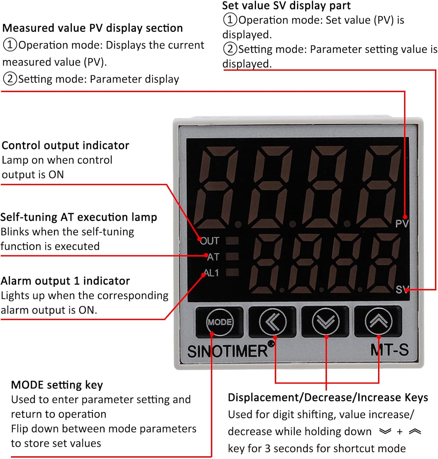
Figure 5.1: Front panel layout of the SINOTIMER PID Temperature Controller, indicating PV/SV displays, control indicators, and function keys.
- PV (Process Value) Display: Shows the current measured temperature.
- SV (Set Value) Display: Shows the target temperature or parameter setting value.
- Indikátor OUT: Lights up when the control output (to SSR) is ON.
- Indikátor AT: Blinks when the self-tuning function is active.
- AL1 Indicator: Lights up when the alarm output is ON.
- Tlačítko MODE: Used to enter parameter settings and navigate between modes. Press and hold to store set values.
- Shift Key (<): Used for digit shifting during value adjustment.
- Decrease Key (↓): Used to decrease values.
- Increase Key (↑): Used to increase values.
5.2 Setting the Target Temperature (SV)
- In normal operation mode, the upper display shows PV (current temperature) and the lower display shows SV (target temperature).
- Použijte Increase (↑) a Decrease (↓) keys to adjust the SV to your desired temperature.
- Použijte Shift (<) key to move the cursor between digits for faster adjustment.
- The new SV will be automatically saved after a few seconds of inactivity or by pressing the MODE klíč.
5.3 Pokročilé nastavení parametrů
To access advanced settings (e.g., PID parameters, alarm settings, input type, unit selection), press and hold the MODE key for several seconds. Use the MODE key to cycle through parameters, and the Shift (<), Increase (↑)a Decrease (↓) keys to adjust values. Refer to the detailed parameter list in the full product manual for specific functions and ranges.
6. Údržba
Regular maintenance ensures the longevity and optimal performance of your PID temperature controller kit.
- Čištění: Periodically clean the controller's front panel with a soft, dry cloth. Do not use abrasive cleaners or solvents.
- Inspekce: Regularly check all wiring connections for tightness and signs of wear or damage. Ensure the thermocouple is securely in place and free from corrosion.
- Chladič: Verify that the heat sink on the SSR is free from dust and debris to ensure efficient heat dissipation.
- Prostředí: Ensure the controller is operated within its specified environmental conditions (temperature, humidity) to prevent malfunction.
7. Řešení problémů
If you encounter issues with your PID temperature controller, refer to the following common problems and solutions:
| Problém | Možná příčina | Řešení |
|---|---|---|
| Ovladač se nezapne | Chybí napájení; nesprávné zapojení | Check power connections (terminals 1 & 2); ensure power source is active. |
| Displej PV zobrazuje „HHHH“ nebo „LLLL“ | Thermocouple open circuit or reverse connection; temperature exceeds range | Check thermocouple wiring and polarity; ensure it's within operating range. |
| Output (OUT indicator) not activating | SV not set correctly; PID parameters incorrect; SSR faulty | Verify SV is below PV (for heating); check PID settings; test SSR functionality. |
| Temperature unstable or overshoots | PID parameters not optimized | Perform auto-tuning (AT function) or manually adjust PID parameters. |
If the problem persists after attempting these solutions, please contact SINOTIMER customer support for further assistance.
8. Bezpečnostní informace
- Always disconnect power before installation, wiring, or maintenance.
- Ensure all wiring is done by a qualified individual and complies with local electrical codes.
- Nepoužívejte zařízení v prostředí s nadměrnou vlhkostí, prachem nebo korozivními plyny.
- The SSR generates heat during operation; ensure adequate ventilation and proper heat sink installation.
- This device is not intended for life-support applications or where malfunction could result in significant injury or damage.
9. Záruka a podpora
For warranty information and technical support, please refer to the product packaging or contact SINOTIMER directly through their official website or the retailer where the product was purchased. Please have your product model number (40DA) and purchase details ready when contacting support.


