![]() C-Series Refrigerant
C-Series Refrigerant
Leak Detection System (CRLDS)
Quick Start Guide

Safety Icon Explanation
![]() DANGER indicates a hazardous situation which, if not avoided, will result in death or serious injury.
DANGER indicates a hazardous situation which, if not avoided, will result in death or serious injury.
![]() WARNING indicates a hazardous situation which, if not avoided, could result in death or serious injury.
WARNING indicates a hazardous situation which, if not avoided, could result in death or serious injury.
![]() CAUTION used with the safety alert symbol, indicates a hazardous situation which, if not avoided, could result in minor or moderate injury.
CAUTION used with the safety alert symbol, indicates a hazardous situation which, if not avoided, could result in minor or moderate injury.
![]() NOTICE is used to address practices not related to personal injury.
NOTICE is used to address practices not related to personal injury.
![]() FLAMMABLE Fire hazard! Sparking in a potentially explosive atmosphere! Explosion hazard!
FLAMMABLE Fire hazard! Sparking in a potentially explosive atmosphere! Explosion hazard!
Instructions Pertaining to Risk of Electrical Shock, Fire, or Injury to Persons
![]()
PLEASE READ BEFORE USING THIS MANUAL
- This manual is part of the product and should be kept near the instrument for easy and quick reference.
- The instrument shall not be used for purposes different from those described hereunder.
It cannot be used as a safety device. - Check the application limits before proceeding.
- Copeland reserves the right to change the composition of its products, even without notice, ensuring the same and unchanged functionality.
![]()
PLEASE READ BEFORE USING THIS MANUAL
- Verify that the supply voltage is correct before connecting the instrument.
- Do not expose the gateway to water or moisture: use the devices only within the operating limits avoiding sudden temperature changes with high atmospheric humidity to prevent formation of condensation.
- Disconnect all electrical connections before any kind of maintenance.
- Fit the transmitter where it is accessible by the end user for troubleshooting and replacement. The instrument must not be opened.
- In case of failure or faulty operation send the instrument back to the distributor or to Copeland with a detailed description of the fault.
Introduction
CRLDS Gas Detectors are used to monitor indoor air for any refrigerant leaks. The devices can be used for refrigeration applications (cold rooms, freezer rooms, machinery rooms).
These detectors are calibrated in various refrigerants available on the market. The sensitive elements are constructed using semiconductor (SC) technology and infrared (IR) technology.
The CRLDS Gas Detectors can be used in stand-alone applications or connected in Copeland Controllers. Communication with controllers uses an analog output, relays, or an RS485 Modbus serial connection. When a refrigerant leakage exceeding a programmable concentration threshold is detected, an alarm or warning status is activated, depending on the level of concentration set, and the CRLDS responds as follows:
- The combination of LEDs that are on changes
- A dedicated internal relay (SPDT) is activated
- The Analog output is controlled (in proportion to the detected concentration
- The change in status is signaled via the RS485 Modbus output
Safety Precautions
![]()
Semiconductor sensors detect the gas they have been calibrated for, but are also sensitive to other types of gases, solvents, alcohol, or substances containing ammonia, such as cleaning products, present in the environment. This, in certain areas and applications, can lead to false alarms when the substances described above are present. Nonetheless, although they do not only detect the specific gas, but they also still give a reliable indication of the concentration of the gas they have been calibrated for.
![]()
This device is neither certified nor approved for operation in oxygen-enriched atmospheres.
Non-compliance can lead to EXPLOSION.
![]()
This device has not been designed to guarantee intrinsic safety when used in areas classified as hazardous (“Directive 2014/34/EU ATEX” and “NFPA 70, Hazardous Location”). For operator safety, DO NOT use it in hazardous locations (classified as such). If the equipment is used in a manner not specified by the manufacturer, the protection provided by the equipment may be impaired.
Technical Specifications
| Technical Specifications | Semiconductor version | Infrared version |
| Power supply voltage** | 24VDC/AC +/- 20%, 5W , 50/60Hz
(Recommended P/N 250-2541 DIN rail mount 24VDC @ 15W power supply) |
|
| User Interface | App with Bluetooth® | |
| Analog Output | 4-20mA / 0-10V / 1-5V / 2-10V selected via software | |
| Serial Communication | Modbus® RS485 isolated server | |
| Digital Output 1 SPDT | Alarm – relay 1 A/24 VDC/AC, resistive load | |
| Digital Output 2 SPDT | Warning/FAULT – relay 1 A/24 VDC/AC, resistive load | |
| Relay Failsafe | Yes; Selectable | |
| Selectable Delay | 0-20 min; 1-minute steps, selectable via Modbus register/app | |
| Hysteresis | ± 10% of the threshold value | |
| IP Protection | IP67 | |
| Typical Operating Range | 0-1000 ppm | 0-10000 ppm |
| Sensing Element | Pre-calibrated (also available as a spare part) with certificate | |
| Remote Cable Length | 5 meters | |
| Storage Ttemperature | -40°F to +122°F (-40 °C to +50 °C) | |
| Storage Humidity | 5-90% relative humidity, non-condensing | |
| Storage Position | Any | |
| Operating Temperature | -40°F to +122°F (-40 °C to +50 °C) | |
| Operating Humidity | 5-90% relative humidity, non-condensing | |
| Maximum Installation Altitude | 2000 meters (6561 ft.) | |
| Operating Position | Intended for vertical mounting with the sensor at the bottom | |
| Precision* | <-10%/+15% | ±5% |
| Start-up Time* | 5 minutes | 2 minutes |
| Working Life* | 5 years | 7 years |
| Calibration Procedure Requirements | 12 months | Not required |
- Reference conditions at 77°F (25°C) 50% RH atmospheric pressure 101.3 kPa
- The device is intended to be supplied from an isolated Limited Energy Source per UL61010-1, 3rd edition cl. 9.4 or Limited Power Source per UL60950-1 or Class 2 per NEC
Installation
General Information
The performance and overall effectiveness of the system strictly depend on the characteristics of the place where the gas detector is installed.
It is therefore necessary to scrupulously comply with and carefully analyze every detail of the installation process, including (but not limited to) the following aspects:
- Local, state and national regulations and standards governing the installation of gas monitoring equipment
- Electrical standards governing the laying and connection of power and signal cables to gas monitoring equipment
- All possible environmental conditions that the devices will be exposed to
- The physical characteristics of the gas to be detected (in particular, its specific weight)
- The characteristics of the application (for example, possible leakages, movement of air, areas where gas may stagnate and collect, high pressure areas, etc.)
- The accessibility needed for routine maintenance and repairs
- The types of equipment and accessories needed to manage the system
- Any limiting factors or regulations that may affect system performance or installations
Installation Tips
![]()
The installation surfaces must not be exposed to continuous vibrations so as to prevent damage to the connections and electronic devices.
![]()
The gas detector must only be installed by qualified personnel. It is recommended to read the full manual completely in order to use the product correctly.
![]()
THERE IS NO GENERAL RULE for establishing the appropriate number of sensors and their location for each application. Therefore, the guidelines described below are intended as support for installers, and not as rules in their own right. Copeland accepts no liability for the installation of the gas detectors.
Sensor Height
| Gas Type | Mounting Height |
| HFC / HFO / C3 H8 Propane (R290) | 20 cm (7.87 in) above the floor |
| CO2 Carbon Dioxide (R744) | 20 cm (7.87 in) above the floor |
Installation Instructions
Once the optimal position to install the sensor has been chosen, it is recommended to install the sensor (identifiable on the device by the black sensor housing) in a vertical position, with the sensitive element (black part) facing downwards. The sensor can now be mounted on the wall, as follows :
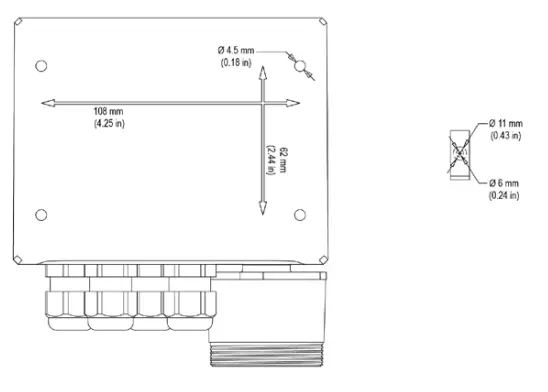
- Drill the holes in the wall using the measures on the bottom side of the detector (shown in the picture).
- Fix the device using four screws, chosen according to the type of installation and the type of wall, maximum diameter 4 mm, minimum length 15 mm and torque 2.5 Nm.
- Fix the remote sensor using one screw, chosen according to the type of installation and the type of wall, maximum diameter 4 mm, minimum length 15 mm and torque 2.5 Nm.
- Open the cover of the device, fit the cable glands and make the required electrical connections. The plug-in terminals can be removed from the device to facilitate wiring.
- Power ON the device and complete the settings using the rotary switch, as described in the following paragraphs, or using the app, as described below or through the Modbus connection.
- Use the cable glands provided to pass through and connect the cables to the terminals, as shown in the figure below and in the Connection Table on page 5. The terminals can be removed to simplify wiring.
- Close the cover.

- Cord range for M16 cable gland 5 – 10 mm, for M22 cable gland 10 -14 mm.
- Use UL listed approved cable, min. 122°F (50°C), suitable for electrical rating in application.
- Tighten the cable glands with a torque of 2.5 Nm.
- Close the cover.

All external circuits connected to device shall be double or reinforced isolated from mains meet SELV and Limited energy requirements according to clause 9.4 of UL61010-1 3rd edition.

- Secure the detector cover with the four screws.
- Power the device on and set the parameters if the settings were not previously made using the rotary switch.
| J1 | + | Analog output |
| G | Analog output reference | |
|
J2 |
Sh | Shielded RS485 cable |
| G0 | GND for RS485 | |
| A | Tx + / Rx + for RS485 | |
| B | Tx- / Rx- for RS485 | |
|
J3 |
+24 Vac/DC | For Vac power supply, connect the second transformer wire |
| +24 Vac/DC | For Vdc power supply, connect one of the two power wires, the device automatically recognizes whether this is + or GND. For AC power supply, connect one of the two transformer wires. | |
|
J4 |
1A | NO contact for the warning/fault relay |
| 2A | Common for the warning/fault relay | |
| 3A | NC contact fo r the warning/fault relay | |
|
J5 |
1B | NO contact for the alarm relay |
| 2B | Common for the alarm relay | |
| 3B | NC contact for the alarm relay | |
|
J6 |
+ | NC contact for the alarm relay |
| G | Service voltage reference | |
| J7 | / | Built-in version sensor connector |
| J8 | / | Remote version sensor connector (connection not to be used for built-in products) |
Connection Table
Installation Reminders
![]()
Before commencing electrical installation and wiring, carefully read the following notes:
- Power must be supplied by a safety isolation transformer (Class 2) or DC power supply with no Earth Ground connection on the low voltage side (24VAC or 24VDC).
- The cable for the relays must be sized and fitted with fuses based on the rated voltages, currents, and environmental conditions.
- If stranded wires are used, it is recommended to use an end terminal.
- To comply with RFI immunity regulations, the Modbus communication cable shield at the supervisor controller (E2, E3, Site Supervisor) end of network must be connected to Earth Ground (for example, to the earthed chassis, earth bar, etc.)
- Complete all wiring before powering on.
Device Operating States
The CRLDS Gas Detectors provide visual indications of their current operating status, in addition to the relay outputs. Visual indication of device operating status is provided by three LEDs (green/red/ orange). Device status and the corresponding outputs are displayed in the following table:
| Status | LED | Warning Fault/Relay | Alarm Relay |
| Warm-up | OFF | OFF | |
| Normal | OFF | OFF | |
| Bluetooth® | OFF | OFF | |
| Serial Connected | Internal LED W8 on steady | — | — |
| Warning Delay | OFF | OFF | |
| Alarm Delay (RWF* = 0) | ON | OFF | |
| Alarm Delay (RWF* = 1) | OFF | OFF | |
| Warning (RWF* = 0) | ON | OFF | |
| Warning (RWF* = 1) | OFF | OFF | |
| Alarm (RWF* = 0) | ON | ON | |
| Alarm (RWF* = 1) | OFF | OFF | |
|
Fault (RWF* = 0) |
ON |
ON |
|
| Red and yellow on steady Green LED OFF | |||
|
Fault (RWF* = 1) |
ON | OFF | |
| Red and yellow on steady Green LED OFF |
* RWF = Relay WF Modbus Register
Copeland CRLDS Application Features
The CRLDS Application lets users fully experience the potential of the new CRLDS detectors, allowing simple and intuitive interaction with the gas detector. This simplifies configuration by usinga smartphone to interface with the CRLDS detector.
The Copeland CRLDS Application is available on the Google Play Store and on the App Store®.
The mobile app can be used to perform the following functions:
- Configuration modify alarm thresholds, configure Modbus settings, modify relay behavior, and manage Analog output settings
- Maintenance check correct functioning of the device
- Calibration, complete with calibration report
- Display of current gas concentration measurement and indication of alarm/fault status
Connecting the Device via Bluetooth®
Before connecting to the device via the Copeland CRLDS Application, first make sure that the Bluetooth® connection and Geolocation are enabled on the smartphone used (Android™ only).
Make sure that Bluetooth® mode has been activated on the CRLDS using the magnetic key, as described in the previous chapter.
Open the mobile app (previously downloaded); the following screen is displayed.
| Login Screen | |
 |
Select |
| Bluetooth® Connection Screen | |
 |
If all the functions described above have been enabled on the smartphone and the Gas Detector is in Bluetooth® mode, the available devices are shown on the app screen. If this is not the case, touch the app screen to refresh the display. Verify that the serial number on the label of the device being connected matches the one displayed on the screen. Select the correct device and verify correct connection. The Bluetooth® symbol at the top right changes from red to green. |
| Home Screen | |
 |
From the home screen, it is possible to display the current concentration level measured by the sensor, with the corresponding alarm and warning thresholds. The following screens can also be accessed: • PARAMETERS • MODBUS SETUP • Test • Calibration • More |
| Parameter Screen | |
 |
This screen displays the sensor parameters. It is also possible to select the type of gas to be detected, from those that are compatible with the sensor. See the other information chapter in this manual for further details. The following parameters can be displayed and modified if the user is logged with Technician access: • Warning (ppm) Threshold for activating Warning. • Warning Reset determines if warning will revert to IDLE automatically if gas levels drop below Warning threshold or requires manual acknowledgement to be reset. • Alarm (ppm) Threshold for activation of Alarm. • Alarm Reset determines if alarm will revert to IDLE automatically if gas levels drop below Alarm threshold or requires manual acknowledgement to be reset. • Relay Warning Fault (RWF) – Activate to turn Warning relay into a dedicated fault relay. • Output type – choose analog output scale for J1. Mode description is in Section 5. Operation. • Alarm delay – the delay in minutes from the measured concentration passes the threshold value to the moment the alarm activates. Affects both Warning and Alarm. • Gas type – the specific gas to be measured. |
| Modbus Setup Screen | |
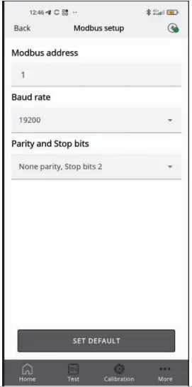 |
The following parameters can be set: • Modbus address • Baud rate • Parity and stop bits Pressing SET DEFAULT sets the default parameters shown in the table in the Modbus setup paragraph (does not affect the Modbus address). |
| Test Mode Screen | |
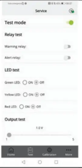 |
If enabled, the following functions can be activated in test mode, specifically not corresponding to the behavior of the device, rather for debugging. • Warning relay • Alarm relay • Green LED • Red LED • Yellow LED • Analog output |
| More Screen | |
 |
Displays the app technical and legal information. • App settings – change the unit of measure for the temperature displayed in the app. • Device Info – view information on the currently connected device. • Create report – make a copy of the most recent report generated. • Change logo – replace the default logo that is shown on the calibration certificate with a different one. • Third party licenses – see information on the third-party licenses used. |
Sensor Replacement Procedure
When the need for replacement is signaled via Modbus communication (coil 311 SensorExpired), proceed as follows
- Acquire a pre-calibrated sensor module with the same part number as the one mounted on the detector.
- Disconnect power.
Built-in Version
- Open the cover.
- Disconnect the sensor connector J7.
- Unscrew the sensor module from the case.
- Screw in the new sensor module.
- Plug-in the sensor connector to terminal J7.
- Close the cover.
Remote Version
| 1. Loosen the cap off the cable gland so that the cable is free to move inside the cable gland. | 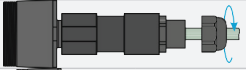 |
| 2. Completely unscrew the cable gland. In the event of difficulties when loosening, use pliers. | 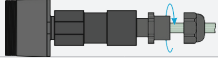 |
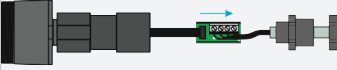
| 3. Pull out the electronic board from its housing by pulling the remote sensor cable. |
|
| 4. Unplug the sensor connector from the electronic board. |
|
| 5. Unscrew the sensor module from the tube so as to separate it from the other parts of the device. | 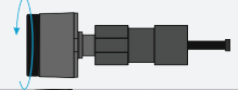 |
| 6. Pull out the sensor module. | 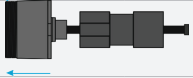 |
| 7. Make sure the new sensor module has the same part number as the one just removed. Mount the sensor module in the opposite order to the above instructions for removal. |
|
Ordering Information
CRLDS Gas Detector Part Numbers
| Part Number | Description |
| 809-1207 | CRLDS Calibration Kit |
| 809-1209 | CRLDS, 0-1000ppm, Remote, SC, Group 1 |
| 809-1210 | CRLDS, 0-1000ppm, Remote, SC, Group 2 |
| 809-1211 | CRLDS, 0-1000ppm, Wall Mount, SC, Group 1 |
| 809-1212 | CRLDS, 0-1000ppm, Wall Mount, SC, Group 2 |
| 809-1213 | CRLDS, 0-10000ppm, Wall Mount, IR, CO2 |
| 809-1214 | CRLDS, 0-10000ppm, Remote, IR, CO2 |
| 809-1221 | CRLDS Sensor Module SC HFC/HFO Group 1, 1000ppm |
| 809-1222 | CRLDS Sensor Module SC HFC/HFO Group 2, 1000ppm |
| 809-1223 | CRLDS Sensor Module IR CO2, 10000ppm |
| Group 1 Gases | R32, R407A, R407C, R407F, R410A, R448A, R449A, R452A, R452B, R454A, R454B, R454C, R455A, R464A, R465A, R466A, R468A, R507A |
| Group 2 Gases | R22, R134a, R404A, R450A, R513A, R1234yf, R1234ze, R1233zde |
For a full copy of the user manual, scan the QR Code:
 https://www.copeland.com/documents/026-1318-crlds-user-manual-en-9291542.pdf
The contents of this publication are presented for informational purposes only and they are not to be construed as warranties or guarantees, express or implied, regarding the products or services described herein or their use or applicability. Copeland reserves the right to modify the designs or specifications of such products at any time without notice. Responsibility for proper selection, use and maintenance of any product remains solely with the purchaser and end-user. ©2023 Copeland is a trademark of Copeland LP.
026-4427| R3 | 1023
copeland.com
Documents / Resources
 |
COPELAND C-Series Refrigerant Leak Detection System [pdf] User Guide C-Series, C-Series Refrigerant Leak Detection System, Refrigerant Leak Detection System, Leak Detection System, Detection System, System |
 |
COPELAND C Series Refrigerant Leak Detection System [pdf] User Guide C Series Refrigerant Leak Detection System, C Series, Refrigerant Leak Detection System, Leak Detection System, Detection System |