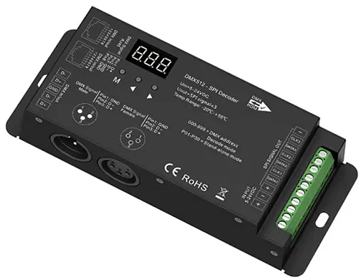
COOPER CLS DMX Decoder DMX Light Controller
Specifications
- Brand: CLS-DMX-DECODER
- Input: 12 – 24VDC
- Output: 12 – 24VDC
- Max Load: 4CH x 5A, 4CH x 192W (24V)
Product Usage Instructions
Safety & Warnings
- Install in accordance with national and local electrical code.
- Make sure power is OFF before starting installation or maintenance.
- Handle the fixture with care due to sharp edges.
- Do not install the fixture in spaces where impacts from objects can occur.
Installation Instructions
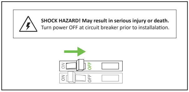
- Turn off power at the circuit breaker before installation.
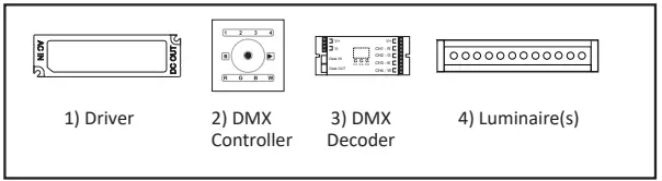
- Determine the location to install components by referring to system diagrams.
- Determine control zones as per the system guide.
- Connect the decoder to the DMX controller following the wiring diagram.
WARNING
- Risk of Fire, Electrical Shock, Cuts or other Casualty Hazards- Installation and maintenance of this product must be performed by a qualified electrician. This product must be installed in accordance with the applicable installation code by a person familiar with the construction and operation of the product and hazards involved.
- Risk of Fire and Electric Shock- Make certain power is OFF before starting installation or attempting any maintenance. Disconnect power at fuse or circuit breaker.
- Risk of Fire- Minimum 90°C supply conductors.
- Risk of Burn- Disconnect power and allow fixture to cool before handling or servicing.
- Risk of Personal Injury- Due to sharp edges, handle with care.
- Risk of Personal Injury- Fixture not intended to be installed in a gymnasium or other space where impacts from objects can occur.
- Failure to comply with these instructions may result in death, serious bodily injury and property damage.
DISCLAIMER OF LIABILITY: Cooper Lighting Solutions assumes no liability for damages or losses of any kind that may arise from the improper, careless, or negligent installation, handling or use of this product.
IMPORTANT: Read carefully before installing fixture. Retain for future reference.
NOTICE: Green ground screw provided in proper location. Do not relocate.
NOTICE: Fixture may become damaged and/or unstable if not installed properly.
Note: Specifications and dimensions subject to change without notice.
ATTENTION Receiving Department: Note actual fixture description of any shortage or noticeable damage on delivery receipt. File claim for common carrier (LTL) directly with carrier. Claims for concealed damage must be filed within 15 days of delivery. All damaged material, complete with original packing must be retained.
SAFETY & WARNINGS
- Install in accordance with national and local electrical code regulations.
- This product is intended to be installed and serviced by a qualified, licensed electrician.
- DO NOT connect directly to high voltage power.
Install with a compatible Class 2 constant voltage LED driver (power supply). - This product is rated for indoor installation and is not protected against moisture.
- Install appropriately rated wire between driver,decoder, and fixture. When choosing wire, factor in voltage drop, amperage rating, and type (in-wall rated, etc.) Inadequate wire installation may cause fire.
- Do not modify or disassemble product beyond instructions or warranty will be void.
MAXIMUM DAISY-CHAIN DMX DECODERS
A maximum of 10x DMX Decoders may be connected together via RJ45 DMX Connection Ports. DMX signal may be extended further by installing a DMX 8-Way Splitter after the 10th DMX Decoder.
QUICK SPECS / MODELS
| Input | Output | Max Load | |
| CLS-DMX-Decoder | 12 – 24VDC | 12 – 24VDC | 4CH x 5A
4CH x 192W (24V) |
- RDM Support: Yes
- Output PWM Frequency: 2KHz
- DMX Splitter Compatible: Yes
- Environment: Indoor Location
Turn Power Off at Circuit Breaker
Determine Location To Install Components
Refer to SYSTEM DIAGRAMS.
Determine Control Zones
Determine and group fixtures to be controlled together and one (1) decoder per run is necessary.
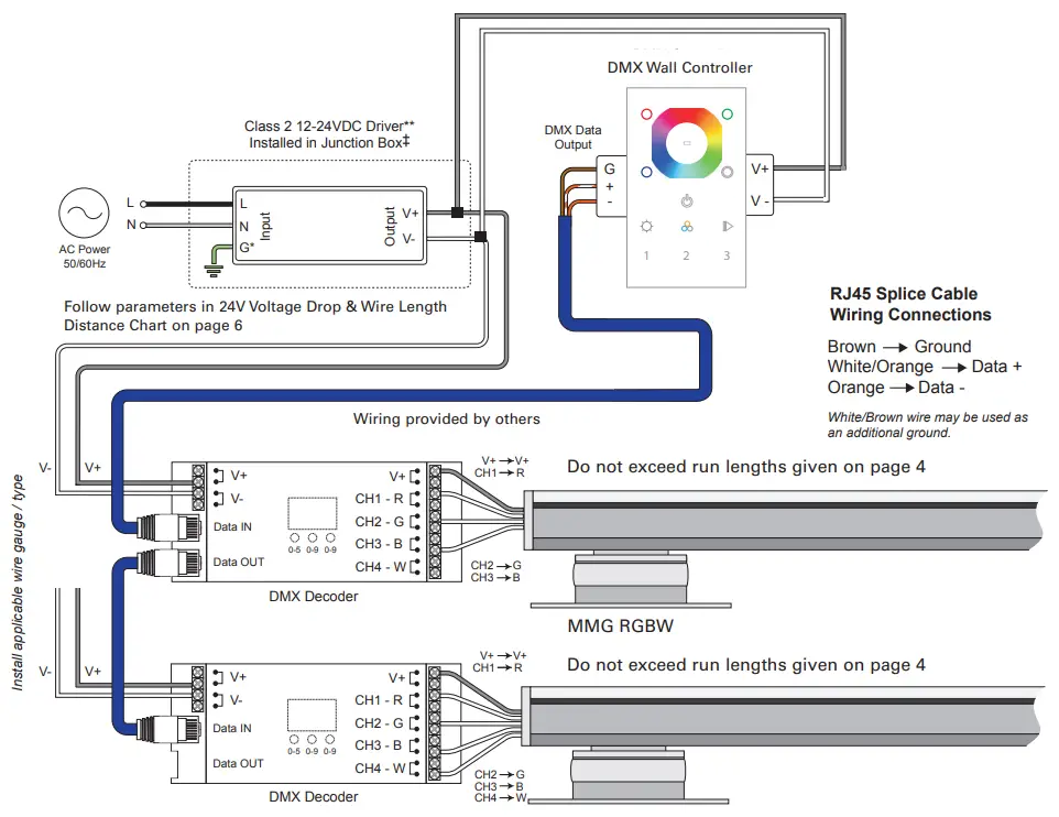
Connect Decoder To Dmx Controller.
DMX Decoder to DMX Controller (see diagram above and wiring diagram).
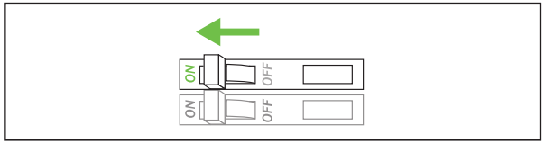
Install Additional Components, Verify
Connections, Turn Main Power On At Breaker.
OPERATION
DMX START CHANNEL DISPLAY
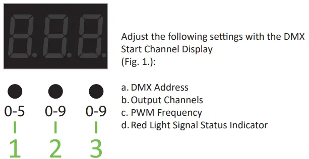
SETTING
SETTING THE DMX ADDRESS
USE THE 3 BUTTONS OF THE DMX START CHANNEL TO ADJUST THE VALUES OF THE DMX ADDRESS. THE DECODER WILL CONTROL UP TO 512 CHANNELS.
- To set the DMX address, press and hold ‘button 1’ for 2 seconds until numbers on display flash.
- Select an address based on the functionality of the primary DMX Controller (see wall / remote control installation guide). Once an address is selected, the remaining 3 channels will be utilized digitally. For example, if the decoder is addressed to 001 on the display then CH1 – 001, CH2 – 002, СН3 – 003, CН4 – 004. (see diagram on page 5 – System Diagram with DMX Wall Controller)
- Once display stops flashing, DMX address is set.
- Hold ‘button 1″ for 3 seconds to confirm the setting
- Indicator light will light red when data signal is confirmed
Cooper Lighting Solutions strongly recommends only professional DMX installers utilize the following settings. All standard DMX applications specified by Cooper Lighting Solutions do not require these settings to be adjusted.
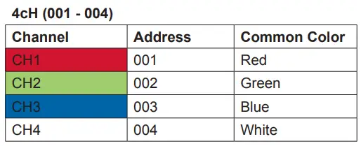
SETTING DMX CHANNELS.
The DMX channels can be adjusted, which allows the user to conserve DMX addresses that may be wasted when programming a large DMX universe!
The factory default is 4 channels and is most commonly used: 4 channels (address 001 – 004) as highlighted in the chart below.
To change channel setting:
- Press and hold ‘button 2 and 3’ simultaneously for 2 seconds until ‘cH’ flashes on display (Fig. 2).
- Press ‘button 1’ to choose 1, 2, 3, or 4 channel outputs (Fig. 3).
- Press and hold any button for >2 seconds to set channel output.
- Hold ‘button 1’ for 3 seconds to confirm the setting
PWM FREQUENCY
The Default PWM frequency is PF2 (2KHz)
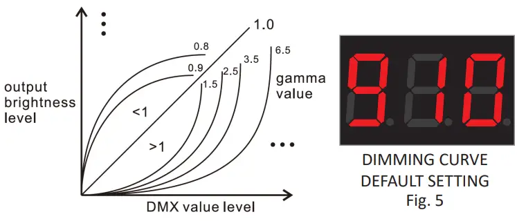
SETTING DIMMING CURVE GAMMA VALUE
The dimming curve gamma value can be adjusted for special applications. Default dimming curve is g1.0 (Gamma 1.0)
To change channel setting:
- Press and hold ‘buttons 1, 2, and 3’ simultaneously for 3 seconds until ‘g1.0’ flashes on display (Fig. 5).
- Press ‘button 2’ and ‘button 3’ to change gamma value.
- Hold ‘button 1’ for 3 seconds to confirm the setting
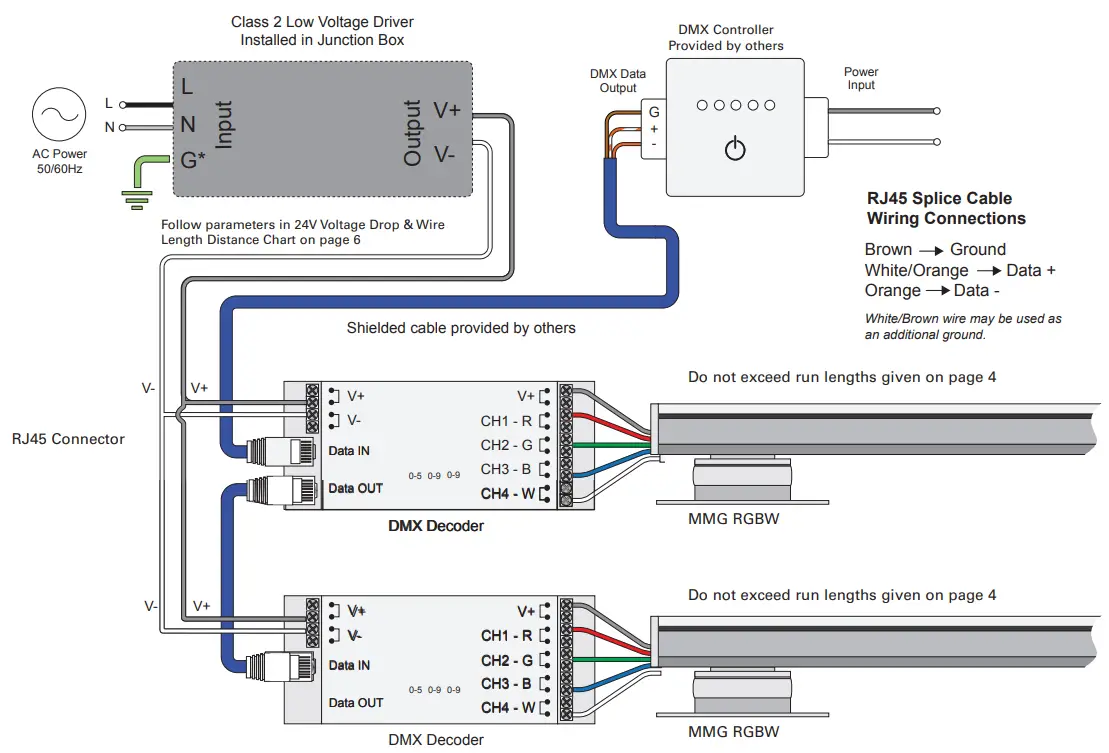
SYSTEM DIAGRAM
The following diagram is provided as an example system design. Shielded CAT (RJ45 connections) data cables are the most cost-effective solution for transmitting DMX-512 signals. Shielded XLR-3 cables are recommended for minimal EMI and require an additional adapter for connecting to DMX decoders.
Note: Shielded cables with RJ45 connections are provided by others.
MAXIMUM RUN LENGTHS
| MMG | Max Run Length of Luminaries | |||
| STD Driver | ND Driver | |||
| W/ft | 90W | 60W | 96W | 60W |
| 03W | 30ft | 20ft | 32ft | 20ft |
| 05W | 18ft | 12ft | 19ft | 12ft |
| 06W | – | – | 14ft | 9ft |
| 08W | 11ft | 7ft | 12ft | 7ft |
** Install a compatible Class 2 constant voltage driver. It is recommended to load the driver no more than 80% its labeled rating for maximum longevity.
‡ Refer to driver specifications for a compatible junction box
TROUBLESHOOTING
| Symptom | Common Cause |
| Fixture responding incorrectly and/or flickering | • Incorrect wiring. Reversing Data + and Data -will cause lights to flicker.
• Ensure compatible constant voltage driver is installed. • Check connections of additional components. |
| Cannot change DMX address | • Hold in button ‘0-5’ for 3 seconds until display flashes continuously, then set address and confirm setting. |
MAXIMUM DAISY-CHAIN DMX DECODERS
A maximum of 10x DMX Decoders may be connected together via RJ45 DMX Connection Ports. DMX signal may be extended further by installing a DMX Splitter after the 10th DMX Decoder.
Consult factory for components.
VOLTAGE DROP CHARTS
For best performance and lumen output, ensure proper wire gauge is installed to compensate for voltage drop of low voltage circuits.
Example: 24V Voltage Drop & Wire Length Chart
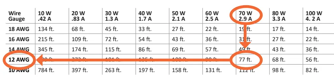
24V Voltage Drop & Wire Length Chart
| Wire Gauge | 10 W
.42 A |
20 W
.83 A |
30 W
1.3 A |
40 W
1.7 A |
50 W
2.1 A |
60 W
2.5 A |
70 W
2.9 A |
80 W
3.3 A |
100 W
4. 2 A |
| 18 AWG | 134 ft. | 68 ft. | 45 ft. | 33 ft. | 27 ft. | 22 ft. | 19 ft. | 17 ft. | 14 ft. |
| 16 AWG | 215 ft. | 109 ft. | 72 ft. | 54 ft. | 43 ft. | 36 ft. | 31 ft. | 27 ft. | 22 ft. |
| 14 AWG | 345 ft. | 174 ft. | 115 ft. | 86 ft. | 69 ft. | 57 ft. | 49 ft. | 43 ft. | 36 ft. |
| 12 AWG | 539 ft. | 272 ft. | 181 ft. | 135 ft. | 108 ft. | 90 ft. | 77 ft. | 68 ft. | 56 ft. |
| 10 AWG | 784 ft. | 397 ft. | 263 ft. | 197 ft. | 158 ft. | 131 ft. | 112 ft. | 98 ft. | 82 ft. |
SEE CLS-DMX-DECODER – DMX 4-CHANNEL DECODER SPECIFICATION SHEET
For full specifications.
Warranties and Limitation of Liability
Please refer to www.cooperlighting.com/Warranty for our terms and conditions.
FCC Statement
This device complies with Part 15 of the FCC Rules.
Operation is subject to the following two conditions:
- This device may not cause harmful interference.
- This device must accept any interference received, including interference that may cause undesired operation.
Note: The grantee is not responsible for any changes or modifications not expressly approved by the party responsible for compliance. Such modifications could void the user’s authority to operate the equipment.
Note: The equipment has been tested and found to comply with the limits for a Class B digital device,pursuant to part 15 of the FCC Rules.
These limits are designed to provide reasonable protection against harmful interference in a residential installation. This equipment generates uses and can radiate radio frequency energy and, if not installed and used in accordance with the instructions, may cause harmful interference to radio communications. However,there is no guarantee that interference will not occur in a particular installation. If this equipment does cause harmful interference to radio or television reception,which can be determined by turning the equipment off an on, the user is encouraged to try to correct the interference by one or more of the following measures:
- Reorient or relocate the receiving antenna.
- Increase the separation between the equipment and receiver.
- Connect the equipment into an outlet on a circuit different from that to which the receiver is connected.
- Consult the dealer or an experienced radio/TV technician for help.
This device complies with FCC radiation exposure limits set forth for an uncontrolled environment. This equipment must be installed and operated in accordance with provided instructions and the antenna(s) used for this transmitter must be installed to provide a separation distance of at least 20 cm from all persons.
Cooper Lighting Solutions
18001 East Colfax Ave
Aurora, CO 80011
1-800-760-1317
www.cooperlighting.com
For service or technical assistance:
1-800-553-3879
Canada Sales
281 Hillmount Rd.
Markham, ON L6C 253
1-800-863-1354
© 2023 Cooper Lighting Solutions
All Rights Reserved
Product availability, specifications,and compliances are subject to change without notice.
FAQ
Q: What should I do if I notice any shortage or damage upon delivery?
A: Note the description of any shortage or noticeable damage on the delivery receipt and file a claim with the carrier. Claims for concealed damage must be filed within 15 days of delivery.
Q: Can the DMX signal be extended further from the RJ45 DMX connection ports?
A: Yes, the DMX signal may be extended further from the RJ45 DMX connection ports.
Q: Is the DMX decoder compatible with DMX splitters?
A: Yes, the DMX decoder is compatible with DMX splitters.
Documents / Resources
 |
COOPER CLS DMX Decoder DMX Light Controller [pdf] Installation Guide CLS DMX Decoder DMX Light Controller, Decoder DMX Light Controller, DMX Light Controller, Light Controller |