Control iD iDFace Max Facial Identification Access Controller

Thank you for purchasing the iDFace Max Facial Recognition Access Controller! For detailed information on how to use your new iDFace Max, please refer to:www.controlid.com.br/userguide/idface-max.pdf By using Control iD products, you agree to the Termsand Conditions of Use and Personal Data ProtectionInformation available at: www.controlid.com.br/legal/eula.pdf
Required Material
To install your iDFace Max, you will need the following items: a drill, wall plugs with corresponding screws, a flathead or Phillips screwdriver, a 12V power supply with at least 2A, and an electric lock. The device can also be powered via the Ethernet connection using PoE infrastructure compatible with IEEE 802.3af. In this case, the device will also provide power to the External Activation Module (EAM).1
- The use of the 12V provided by PoE is exclusively for powering the EAM. Any other use (such as parallel connections with other devices) constitutes a warranty violation and exempts the manufacturer from liability.
Installation
For the optimal operation performance of your iDFace Max, the following precautions must be taken:
- Install in a location without direct sunlight exposure. Lighting should be considered for better image capture quality.
- Avoid placing metallic objects near the back of the device to prevent interference with the proximity card reader range. If unavoidable, use insulating spacers.
- Before securing the device, ensure all connection cables have been properly routed to the equipment.
- Mount the top of the iDFace Max at 1.5m from the ground for pedestrian use or at 1.35m for vehicle use. Installing the equipment is simple and must follow the diagram below:

- For increased installation security, place the External Activation Module (EAM) in a secure area (inside the premises). The iDFace Max EAM is compatible with the rest of the Control iD product line, but EAMs manufactured before July 2024 are not compatible with the iDFace Max due to current consumption (2A peaks).
- Use the template on the back of this guide to drill the 5 mounting holes for the iDFace Max and insert the wall plugs.
- Connect the EAM to a +12V power source and to the lock being controlled using the provided cables.
- Run a 4-conductor cable to interconnect the EAM and the iDFace Max. For distances greater than 5m, use thicker cables and twisted pairs for the data signals. If using a Cat5 cable to connect the EAM to the iDFace Max, use 3 pairs for power and 1 pair for data signals. In this case, the distance should not exceed 25m. Remember to use the same pair for signals A and B.
Recommended installation configuration for Cat5 cable:+12V Green+Orange+Brown GND Green/Wh + Orange/Wh + Brown/Wh A Blue B Blue/Wh - The face Max can continuously consume over 1A, so use thick-gauge cables or combine multiple pairs to facilitate current conduction.
- Connect the wiring harness provided with the iDFace Max to the 4-conductor cable from the previous step.
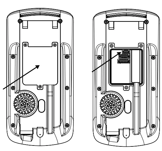
- Remove the wall mount bracket from the iDFace Max.
- Screw the wall mount bracket into the wall plugs. Remove the sealing cover on the back and connect the iDFace Max to the 4-conductor cable.
- Reposition and secure the cover and sealing gasket.
The cover and sealing gasket are essential for ensuring IP65 protection. Make sure they are properly positioned and secured on the back of the product. - Place the iDFace Max on its wall mount and secure it with the screw and tool provided along with the connection cables.

Description of Connection Pins
On your iDFace Max controller, there is a connector input on the back of the device in addition to the network (Ethernet) connector input. On the External Activation Module (EAM), there are 4 other connectors that will be used for connecting locks, REX, sensors, and readers as explained below.
iDFace Max – 4-pin connector (Power + Data) 
iDFace Max – 7-pin connector (Expansion) 
The GPIO pins and the relay integrated into the equipment are configurable via firmware.
iDFace Max – 8-pin connector (Expansion) 
EAM – 4-pin connector (iDFace Max connection) 
EAM – 2-pin connector (Power) 
- Connection to a +12V source of at least 2A is essential for the correct operation of the equipment
EAM – 5-pin connector (Wiegand In/Out) 
External card readers must be connected to the Wiegand inputs WIN0 and WIN1. If there is a controller board, we can connect the Wiegand outputs WOUT0 and WOUT1 so that the user ID identified on the iDFace Max is transferred to the controller.
EAM – 6-pin connector (Door Control/Relay)

The REX and door sensor inputs are configurable as NO or NC and must be connected to “dry contacts” (switches, relays, etc.) between GND and the respective pin.
EAM – Communication Modes
- Standard: EAM will communicate with any equipment
- Advanced: EAM will only communicate with the equipment to which it was configured in this mode
To reset the EAM to its default mode, turn it off, connect the WOUT1 pin to BT, and then turn it on. The LED will blink quickly 20 times, indicating that the reset has been completed.
Configuring your iDFace Max
All parameters of your new iDFace Max can be configured through the LCD (Graphical user interface – GUI) and/or through a standard web browser (provided the iDFace Max is connected to an Ethernet network and has this interface).To configure, for example, the IP address, subnet mask, and gateway via the touchscreen, follow these steps: Menu → Settings → Network. Update the information as desired and connect the device to the network.
Configuration Web Interface
First, connect the device directly to a PC using a network cable (cross or point-to-point). Then, set a static IP on your machine in the 192.168.0.xxx network (where xxx is different from 129 to avoid an IP conflict) with a subnet mask of 255.255.255.0. To access the device’s configuration screen, open a web browser and enter the URL: http://192.168.0.129 The login screen will appear. By default, the access credentials are:
- Username: admin
- Password: admin
Through the web interface, you can change the device’s IP address. If you change this parameter, be sure to write down the new value so you can reconnect to the device.
User Registration and Identification
The effective operation of the facial recognition system is directly related to the quality of the image captured by the face Max during the registration phase. Therefore, during this process, ensure that the face is aligned with the camera at a distance of 50 cm. Avoid atypical facial expressions and objects that may obscure important areas of the face (such as masks, sunglasses, and others). Keep in mind that the photo should be taken as in a personal document. For the identification process, position yourself in front of and within the ca era’s field of view on the iDFace Max, and wait for the access granted or denied indication on the device.
- Avoid using objects that can block the capture of the eyes.
- It is recommended that the distance between the device and the user (with a height of 1.45-1.80 m) be between 0.5 and 1.5 m. Ensure that you are positioned within the ca era’s field of view.

Types of Locks
The iDFace Max, through a relay in the External Activation Module (EAM) of up to 30V and 5A, is compatible with virtually all types of locks available on the market.
Electromagnetic Lock
The electromagnetic lock, or Magnetic Lock, consists of a coil (fixed part) and a metal piece (armature) that is attached to the door (moving part). As long as current flows through the electromagnet, the fixed part will attract the moving part. When the distance between these two parts is small, i.e., when the door is closed and the armature is aligned with the fixed part, the attractive force between them can exceed 1000 kgf. Thus, the electromagnetic lock is typically connected to the NC contact of the relay, as we usually expect current to pass through the electromagnetic. If we want the door to be opened, the relay must open and interrupt the current flow. In this guide, the electromagnetic lock will be represented by 
Solenoid Pin Lock
The solenoid pin lock, also known as a solenoid lock, consists of a fixed part with a moving pin connected to a solenoid. The lock typically comes with a metal plate that should be attached to thedoor (moving part). The pin in the fixed part entersthe metal plate, preventing the door from opening. In this guide, the pin-spring lock will be represented by: 
- Terminals indicated in gray may not be present on all locks. If there is a power input (+12V or +24V), it is essential to connect it to a source before operating the lock.
Electromechanical Lock
The electromechanical lock, or strike, consists of a latch connected to a solenoid through a simple mechanism. After the door is opened, the mechanism returns to its initial state, allowing thedoor to close.Thus, the electromechanical lock typically has twocontacts directly connected to the solenoid. Whencurrent passes through the lock, the door will beunlocked. In this guide, the electromechanical lock will be represented by: 
Confirm the operating voltage of the lock before connecting it to the iDFace Max! Many electromechanical locks operate at 110V/220V and therefore require a different connection.
Connection Diagrams
Connection of iDFace Max and EAM – Mandatory 


- It is mandatory to use a separate external power supply exclusively for powering locks, electromagnetic locks, and general latches.

Documents / Resources
 |
Control iD iDFace Max Facial Identification Access Controller [pdf] User Guide iDFace Max Facial Identification Access Controller, iDFace Max, Facial Identification Access Controller, Identification Access Controller, Access Controller |