![]() iDFace
iDFace
Wiegand and OSDP
Configuration Quick Guide Revision 1.2
Disclaimer
This manual is provided as is and the information contained herein is subject to change without notice. The images in this manual are for illustrative purposes only.
Reproduction, adaptation, or translation, in whole or in part, of this manual is prohibited without express written permission from Control iD.
© 2024 Control iD.
| Revision | Date | Changes | Author |
| Revision 1.0 | August 16th 2024 | Initial revision | André Curvello |
| Revision 1.1 | August 19th 2024 | Improvements after review | André Curvello |
| Revision 1.2 | September 10th 2024 | Addition of examples for iStar Edge and Aero X1100 | André Curvello |
Introduction
The iDFace access controller, developed by Control iD, allows identification through facial recognition, PIN, QR Code, proximity cards or passwords.
This manual serves as a reference for users who wish to integrate their solution with the iDFace access controller over Wiegand or OSDP interfaces.
Wiegand Interface
The Wiegand interface is used mainly when interfacing with legacy solutions. Its main purpose is to transmit numeric card information between a reader and an access controller, which will process that information together with proper access control rules and execute related actions (door opening, etc.).
iDFace can act as a Wiegand reader, sending numeric card information over the Wiegand output signals of its EAM (External Access Module). Therefore, when the Wiegand interface is required, the usage of the EAM module is mandatory.
Please observe the proper polarity for the DATA0/DATA1 output signals (cables yellow-white and yellow).
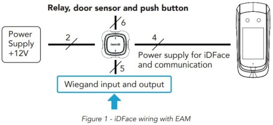 EAM: 5 – Pin Connector (Wiegand In/Out)
 Figure 2 – EAM Wiegand signals.
1.1. EAM (SecBox) interfaces
The External Access Module, also known as SecBox, has 4 different connectors, presented below:
- Power connector: +12V and GND signals for power supply.
- Relay/Door signals: Signals for relay control (NO/COM/NC), plus signals for REX (BT e.g. REX) and DS (door sensor).
- Power + Rs-485 connector: This connector is used to provide power supply and the RS-485 bus to the Control iD access control terminal compatible with the SecBox (as the iDFace).
- Wiegand connector: This connector has the WIN1 and WIN0 signals for Wiegand Input signals, plus WOUT1 and WOUT0 for Wiegand Output signals. The input signals are used for receiving data from external readers, and the output signals are used for the transmission of Wiegand data from the access control terminal connected to the SecBox.
 Figure 3 – EAM connectors.
1.2. EAM (SecBox) wiring for Wiegand interface with Access Control Panel
As mentioned before, to have the iDFace transmit Wiegand data to a given Access Control Panel, it’s necessary to use the EAM (SecBox), which will provide the necessary Wiegand Output Signals to be connected to the desired Reader interface on the other end.
This is exemplified below, taking as example the iDBox, an Access Control Panel from Control iD, capable of interfacing with up to 4 different Wiegand Readers. In the example below, the Wiegand Output signal from a given SecBox is connected to the Reader 1 Wiegand Signals at the iDBox.
The moment an identification is made at the Access Control Terminal connected over RS-485 to the SecBox, it will forward that information over the Wiegand Output signals from the SecBox, being received by the iDBox in its Wiegand Reader interface connected to it.
It’s important to mention that both the Access Control device and the Access Control panel must have the same Wiegand configuration set (e.g. Wiegand 26 bits configuration).
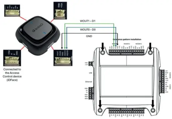 Figure 4 – EAM connection over Wiegand with iDBox.
1.3. EAM (SecBox) wiring for Wiegand interface with iStar Edge
The iStar Edge has two Wiegand Reader interface on each side, each one with the sequence of connections observed in the Figure 5.
As shown in the Figure 5, connect the +12 to +12V to the EAM and GND to GND to provide power to the iDFace from the iStar Edge.
As the iStar Edge can provide up to 12V 1.5 A power to external devices, it works fine with iDFace’s power requirements.
For the Wiegand signals, please wire D0 and D1 to WOUT0 and WOUT1, from iStar Edge to EAM, respectively.
 Figure 5 – EAM connection over Wiegand to iStar Edge.
1.4. EAM (SecBox) wiring for Wiegand interface with Aero X1100
The HID Aero X1100 has two reader interfaces (Reader 1 and Reader 2) that can be used for Wiegand or for RS-485 (OSDP interface). When configured to operate in Wiegand, the Reader interface of Aero X1100 and the EAM can be wired as exemplified in the Figure 6, in which the signals D0/D1 from the Reader 1 of X1100 are connected to WOUT0 and WOUT1 of the EAM, respectively.
 Figure 6 – HID Aero X1100 interface with EAM over Wiegand.
The X1100 can also provide power to the Reader, in this case, the iDFace, but the documentation of X1100 states that X1100 can provide 12 V and 500 mA to each reader. This is not enough to provide power for the iDFace, therefore, it’s recommended to use an external power supply for the iDFace when using it together with Aero X1100.
1.5. Wiegand Configuration
iDFace, as of the V6.16.9 firmware, has plenty of combinations to its Wiegand interface for external devices (or external access controllers).
When interfacing the iDFace with other devices over Wiegand, it’s recommended to set the Wiegand mode for “ID”, which is the default mode. That way, the user’s ID will be sent over Wiegand during the facial recognition process.
Optionally, it is possible to configure a specific code to be sent over Wiegand when facing denied transactions (not authorized or not recognized).
iDFace supports Wiegand configurations from 26 bits (W26) to 66 bits (W66), and you can also change the byte order from MSB (Most Significant Byte first) to LSB as required for the interface with Other Wiegand reader interfaces.
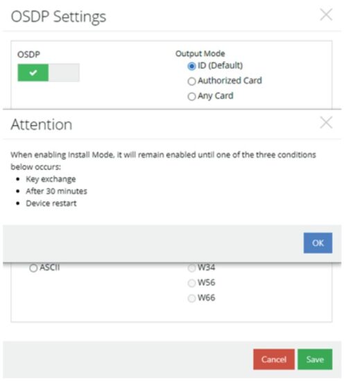
The supported modes for Wiegand output are 3:
- ID (default) – The device will handle access control rules, and it will output the user’s ID over Wiegand. It’s useful for using the device for handling user’s authentication data apart from only card information. In this way, despite the user being authenticated through his face, card, QR Code, PIN or Password, the ID being sent will be the same.
- Authorized Card – The device will handle access control rules in itself and will only output Wiegand information of authorized cards presented to the device.
- Any Card – The device will send any card read by it through Wiegand. This mode is useful if you want the device to act as a plain card reader, without access control rules.
1.5.1. Where to configure Wiegand?
Web interface: Settings > Wiegand Settings.
Graphical User Interface (GUI): Menu > Access > Next > Wiegand

OSDP Interface
OSDP is a state-of-the-art interface between a Peripheral Device (PD), which will interact with the user, and a Control Panel (CP), which will interact with the PD exchanging data and commands. The benefits of OSDP are the possibility of sending messages to appear on the device’s display, the capability of dealing with data in formats apart from the numeric-only Wiegand, and the secure channel that can be stablished between the PD and CP, avoiding that third parties sniff the data being exchanged for malicious usage.
It’s possible to use the iDFace as a Peripheral Device (PD) with a Control Panel (CP) over OSDP, with the following considerations:
- You will need to use the RS-485-A and RS-485-B signals from its 4-pin connector in its back, as shown below.
- The External Access Module will not be used in OSDP Mode.
- The device will need direct 12V 2A power supply to be provided in its 4-pin connector +12V/GND signals to operate.
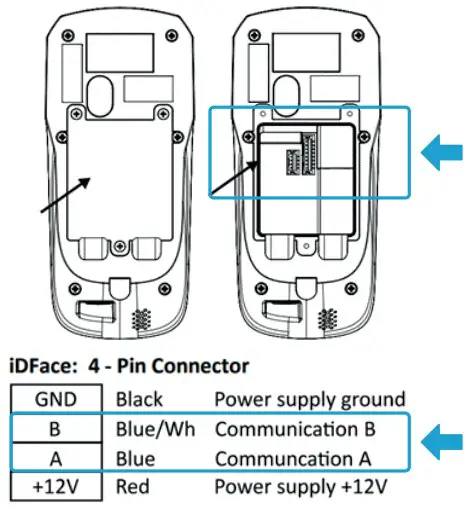 Figure 7 – iDFace back view with emphasis on RS-485/Power terminal.
2.1. RS-485 Wiring for OSDP interface between iDFace and a Control Panel
As mentioned before, the iDFace is capable to communicate over RS-485 to act as a Peripheral Device in OSDP. This requires the usage of the RS-485 signals in the back of the iDFace.
To have the iDFace to communicate with a given OSDP Control Panel (CP), you must connect the RS-485 A and B signals of the iDFace to the same RS-485 A/B signals at the OSDP Reader interface at the Control Panel.
This is exemplified below, taking as example the upcoming iDBox support for OSDP, in which the D0/D1 signals of a given reader interface can be set for OSDP, thus, assuming the roles of RS-485 A/B signals, respectively.
Depending on the Control Panel, it may have the power signals to provide power supply to the iDFace. Otherwise, the necessary power supply signals must be set apart.
The moment an identification is made at the iDFace acting as a Peripheral Device, connected over RS-485 directly to the Control Panel, it will forward that information over OSDP as a Card Data Report message.
It’s important to mention that both the iDFace and the Control Panel must have set the same baud rate for communication (e.g. 9600). Other configurations are also required (Module Address, Secure Channel, among others presented in the next section).
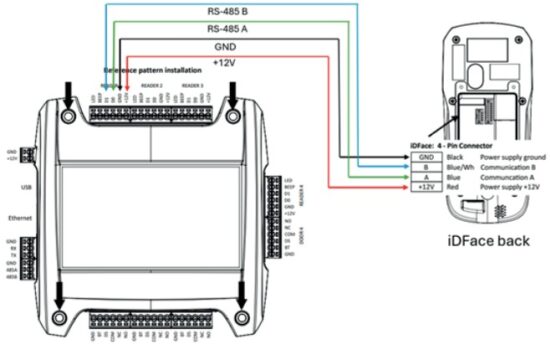 Figure 8 – iDBox and iDFace interface over OSDP using RS-485.
2.2. RS-485 Wiring for OSDP interface between iDFace and iStar Edge
The iStar Edge has up to 3 RM (Reader Module) interfaces, which can be used to connect modules through RS-485 communication.
Each of those RM interfaces can be used to connect the iDFace through its RS-485 signals, when configured to operate in OSDP.
Please observe the wiring presented in the Figure 9, in which the D+ and D- from the RM interface should be connected to A/B to the iDFace 4-pin connector. GND and +12V should be connected accordingly from RM interface to iDFace as well.
As the iStar Edge can provide up to 12V 1.5 A power to external devices, it should work fine with the iDFace power requirements.
 Figure 9 – iStar Edge interface with iDFace over OSDP using RS-485.
2.3. RS-485 Wiring for OSDP interface between iDFace and Aero X1100
The HID Aero X1100 has two reader interfaces (Reader 1 and Reader 2) that can be used or to Wiegand interface, or to RS-485 for OSDP interface. When configured to operate in OSDP, the Reader interface at Aero X1100 and the iDFace can be wired as exemplified in the Figure 10, in which the signals A/B of the Reader 1 at X1100 are connected to A/B of the iDFace, respectively.
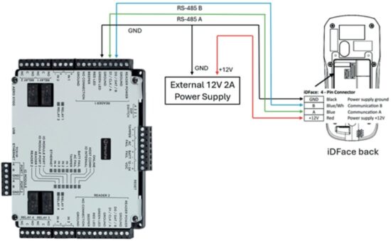 Figure 10 – HID Aero X1100 interface with iDFace over OSDP through RS-485.
The X1100 can also provide power to the Reader, in this case, the iDFace, but the documentation of X1100 states that X1100 can provide 12 V and 500 mA to each reader. This is not enough to provide power for the iDFace, therefore, it’s recommended to use an external power supply for the iDFace when using it together with Aero X1100.
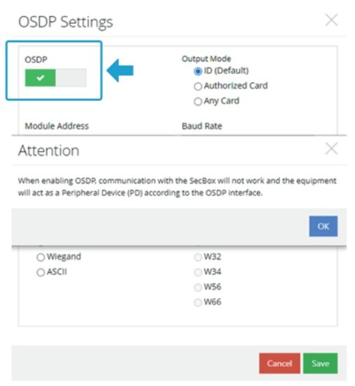
2.4. Enabling OSDP Mode in iDFace
By default, the device is set to operate with the External Access Module (EAM – also called “SecBox”).
To use the iDFace with OSDP, it’s necessary to remove the EAM (“SecBox”) and enable the OSDP mode in the OSDP settings interface.
A warning will pop-up informing the new behavior. Click Ok, then Save.
It’s required to reboot the device after this step.
2.4.1. Where to configure OSDP?
- Web interface: Settings > OSDP Settings.
- Over Display: Menu > Access > Next > OSDP
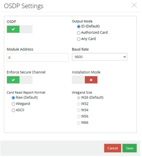
2.5. OSDP Configuration
iDFace is compatible with OSDP and with the security steps required to establish Secure Channel and exchange keys with a CP. To configure this, Installation Mode needs to be enabled.
Default settings:
- Module address: 0
- Baud rate: 9600
Like the Wiegand settings, the output mode of OSDP is also the user’s ID.
Over OSDP iDFace will report identification events as “card read” messages.
It’s also possible to change the card format and the Wiegand bit count in the following options:
- Raw (default): The card data bits are being sent as they were read from the card. 2.
- Wiegand: The card data information is being sent in Wiegand format (area, code) with the resolution in bits set the Wiegand Size.
- ASCII: The card data information is sent in a char array format (ASCII).
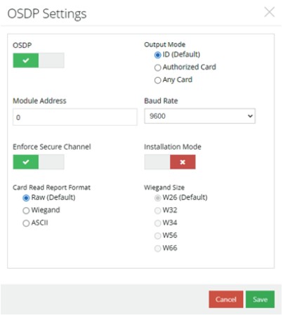
2.6. OSDP Secure Channel and Installation Mode
Once OSDP is enabled, you can enable Secure Channel by setting the option “Enforce Secure Channel”. iDFace’s OSDP Secure Channel implementation is compliant with SIA OSDP V2.2 AES 128.
Secure Channel is highly recommended to establish a protected OSDP communication between the iDFace and the Control Panel.
To exchange keys with the CP, Installation Mode is required to be temporarily enabled.
Once enabled, Installation Mode will be automatically disabled when the key exchange occurs successfully, or after 30 minutes without keys exchange, or after the device restart.
After the key exchange process, iDFace will store the communication keys, and will only renew it after a new Installation Mode command.
OSDP and Wiegand usage suggestion
3.1. User ID as “card”
- As the default type of output over Wiegand or OSDP is the user’s ID, if your system already has a database of cards and you want to switch to a facial recognition solution, one suggestion is to fill in the User ID field with the user’s card number.
- In the example to the left, every time the user “André Curvello” is identified, the iDFace will send over Wiegand or OSDP the number 1234.
- You may need to change or adapt Wiegand format as required (W26 / W32 / W66, for example).
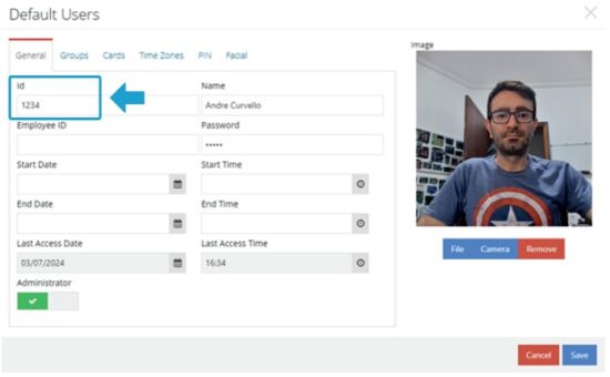
3.2. Enable at least one administrator
To restrict the access to the Menu (Graphical User Interface – GUI), please enable at least one administrator.

iDFace
Wiegand and OSDP Configuration Quick Guide![]()
Documents / Resources
 |
Control iD iD Face Face Reconginition Access Controller [pdf] User Guide iD Face Face Reconginition Access Controller, iD Face, Face Reconginition Access Controller, Reconginition Access Controller, Access Controller, Controller |