![]() 97G2V
97G2V
PRODUCT SPECIFICATIONS
TWO STAGE VARIABLE SPEED
GAS FURNACE FORM NO. 97G2V-100 (10/2023)
97G2V Two Stage Variable Speed Gas Furnace
CONFIGURATIONS
- Upflow / Horizontal
- Downflow
VENTING
- 2-speed induced draft motor with stainless steel shaft, steel ball bearings, and fan cooled for long life
- Vent materials for Canadian applications must comply with ULC S636
- Certified for direct vent (2-pipe) or non-direct (1-pipe) applications
- Direct vent refers to a combustion air supply intake pipe installed in conjunction with flue gas vent pipe.
INSTALLATION FEATURES
- Left or right gas and electric entry
- Zero step horizontal conversion
- Removable floor base (upflow/horizontal units) for bottom return air
- All models comply with California’s South Coast Air Quality Management district Low NOx requirements

HEAT EXCHANGER DESIGN
- Aluminized steel primary heat exchanger with crimped nonwelded construction
- AL29-4C Stainless steel secondary heat exchanger
- Non-welded crimped S-curve primary heat exchanger design for maximum durability
BURNERS
- Aluminized steel in shot burners for smooth ignition
- Isolated burner enclosure for quiet operation
CABINET CONSTRUCTION
- Compact 33″ height
- Standardized widths for easy coil fit
- Unitized construction for cabinet integrity
- Heat exchanger compartment is insulated to increase efficiency and reduce sound levels
- Baked on pre painted steel cabinet finish
AIR DELIVERY SYSTEM
- Efficient ECM variable speed blower motor
- Motor features “soft start” and “soft stop” for quiet operation
- Active and passive dehumidification feature
- Easily removable slide-out blower design
- Dynamically balanced blower wheel with resilient motor mounts for smooth and quiet operation
CONTROLS
- Two stage gas valve
- Integrated ignition and fan control
- System Sentry™ control retains last five (5) fault codes with push button memory recall, regardless of power interruption
- Hot surface ignition system uses silicon nitride ignitor
- Control features 120 volt electronic air cleaner and humidifier terminals
- Control circuit is fuse protected
- Color coded control wiring
- Compatible with single or two stage thermostats for heating.
- Two stage thermostat is recommended when installed with two stage cooling unit.
WARRANTY
10 year limited parts warranty / lifetime heat exchanger warranty available. See limited warranty document for details.
California Only
If installed in South Coast Air Quality Management District (SCAQMD) only: This furnace does not meet the SCAQMD Rule 1111 NOx emission limit (14 ng/J), and thus is subject to a mitigation fee of up to $450. This furnace is not eligible for the Clean Air Furnace Rebate Program: www.CleanAirFurnaceRebate.com.
If installed in San Joaquin Valley Air Pollution Control District (SJVAPCD) only: This furnace does not meet the SJVAPCD Rule 4905 NOx emission limit (14 ng/J), and thus is subject to a mitigation fee of up to $450.
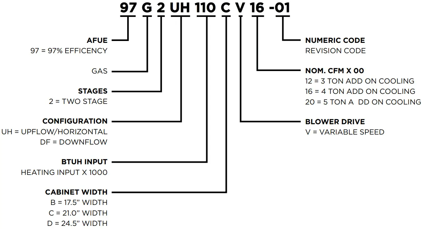
MODEL NUMBER GUIDE
PHYSICAL AND ELECTRICAL DATA
| MODEL | 1ST STAGE | 2ND STAGE | AFUE (ICUS) | NOM. COOLING CAPACITY (TONS) | GAS INLET (IN.) | VOLTS/ HZ/ PHASE | MIN. TIME DELAY BREAKER OR FUSE | NOMINAL F.L.A. | TRANS. (V.A.) | APPROX. WEIGHT (LBS.) | |||
| INPUT (BTUH) | OUTPUT (BTUH) | INPUT (BTUH) | OUTPUT (BTUH) | ||||||||||
| UPFLOW/HORIZONTAL | 97G2UH045BV12 | 29,000 | 28,000 | 44,000 | 43,000 | 97.0 | 3 | 1/2 | 120-60-1 | 15 | 7.7 | 40 | 120 |
| 97G2UH070BV12 | 43,000 | 42,000 | 66,000 | 64,000 | 97.0 | 3 | 1/2 | 120-60-1 | 15 | 7.7 | 40 | 124 | |
| 97G2UH090CV12 | 57,000 | 56,000 | 88,000 | 85,000 | 97.0 | 3 | 1/2 | 120-60-1 | 15 | 7.7 | 40 | 144 | |
| 97G2UH090CV20 | 57,000 | 56,000 | 88,000 | 86,000 | 97.0 | 5 | 1/2 | 120-60-1 | 20 | 12.8 | 40 | 153 | |
| 97G2UH110CV20 | 72,000 | 70,000 | 110,000 | 107,000 | 97.0 | 4 | 1/2 | 120-60-1 | 15 | 12.8 | 40 | 159 | |
| 97G2UH135DV20 | 86,000 | 84,000 | 132,000 | 127,000 | 97.0 | 5 | 1/2 | 120-60-1 | 20 | 12.8 | 40 | 178 | |
| DOWNFLOW | 97G2DF070BV16 | 43,000 | 42,000 | 66,000 | 64,000 | 97.0 | 4 | 1/2 | 120-60-1 | 15 | 10.1 | 40 | 136 |
| 97G2DF090CV20 | 57,000 | 56,000 | 88,000 | 86,000 | 97.0 | 5 | 1/2 | 120-60-1 | 20 | 12.8 | 40 | 152 | |
| 97G2DF110CV20 | 72,000 | 70,000 | 110,000 | 108,000 | 97.0 | 5 | 1/2 | 120-60-1 | 20 | 12.8 | 40 | 163 | |
Note: For vent length and clearances to combustibles, please reference installation instructions.
FILTER REQUIREMENT DATA
| Airflow Descriptor | Disposable Filters | Cleanable Filters |
| Minimum Area (sq. in.) | Minimum Area (sq.in.) | |
| 12 | 576 | 288 |
| 16 | 768 | 384 |
| 20 | 960 | 480 |
- The Airflow Descriptor is the two digits following the “B” , “C”, or “D” in the model number; e.g. “20” is the Airflow Descriptor.
- Areas shown for permanent filters are based on filters rated at 600 feet per minute face velocity.
BLOWER PERFORMANCE DATA – UPFLOW / HORIZONTAL
| MODEL | MOTOR SIZE (HP) | BLOWER SIZE | HEATING TEMP. RISE (°F) | HEATING CFM @ .10″ – .80″ W.C. | COOLING STAGE | COOLING CFM @ .10″ – .80″ W.C. | SPEED ADJUST. | |||||||
| SETTING “D” | SETTING “C” | SETTING “B” | SETTING “A” | SETTING “D” | SETTING “C” | SETTING “B” | SETTING “A” | |||||||
| UPFLOW / HORIZONTAL | 97G2UH045BV12 | 1/2 | 10×9 | 35-65 High Fire | 745 | 875 | 990 | 1005 | 2nd Stage | 905 | 1075 | 1210 | 1370 | + |
| 685 | 765 | 895 | 910 | 815 | 980 | 1120 | 1255 | Norm | ||||||
| 610 | 695 | 785 | 810 | 720 | 885 | 1020 | 1135 | – | ||||||
| 20-50 Low Fire | 685 | 765 | 895 | 910 | 1st Stage | 595 | 760 | 865 | 980 | + | ||||
| 620 | 705 | 800 | 820 | 540 | 660 | 785 | 890 | Norm | ||||||
| 545 | 625 | 715 | 725 | 485 | 600 | 695 | 790 | – | ||||||
| 97G2UH070BV12 | 1/2 | 10×9 | 50-80 High Fire | 965 | 1060 | 1130 | 1255 | 2nd Stage | 860 | 1060 | 1215 | 1365 | + | |
| 880 | 960 | 990 | 1140 | 810 | 960 | 1130 | 1265 | Norm | ||||||
| 810 | 840 | 890 | 1030 | 705 | 840 | 1005 | 1140 | – | ||||||
| 25-55 Low Fire | 940 | 990 | 1070 | 1195 | 1st Stage | 600 | 740 | 840 | 970 | + | ||||
| 830 | 895 | 965 | 1100 | 555 | 665 | 770 | 855 | Norm | ||||||
| 755 | 825 | 840 | 975 | 500 | 600 | 680 | 790 | – | ||||||
| 97G2UH090CV12 | 1/2 | 10×9 | 60-90 High Fire | 1060 | 1135 | 1240 | 1315 | 2nd Stage | 875 | 1040 | 1210 | 1360 | + | |
| 960 | 1040 | 1120 | 1199 | 800 | 945 | 1100 | 1245 | Norm | ||||||
| 830 | 935 | 980 | 1084 | 720 | 840 | 970 | 1115 | – | ||||||
| 30-60 Low Fire | 960 | 1040 | 1120 | 1206 | 1st Stage | 625 | 710 | 830 | 950 | + | ||||
| 875 | 945 | 995 | 1100 | 565 | 670 | 760 | 860 | Norm | ||||||
| 790 | 840 | 920 | 950 | 520 | 610 | 685 | 785 | – | ||||||
| 97G2UH090CV20 | 1 | 11×11 | 40-70 High Fire | 1450 | 1565 | 1725 | 1865 | 2nd Stage | 1385 | 1595 | 1820 | 2020 | + | |
| 1310 | 1450 | 1585 | 1690 | 1225 | 1465 | 1645 | 1885 | Norm | ||||||
| 1155 | 1305 | 1450 | 1545 | 1065 | 1320 | 1504 | 1675 | – | ||||||
| 25-55 Low Fire | 1120 | 1265 | 1420 | 1520 | 1st Stage | 935 | 1055 | 1275 | 1465 | + | ||||
| 965 | 1120 | 1285 | 1395 | 835 | 980 | 1120 | 1335 | Norm | ||||||
| 865 | 950 | 1120 | 1235 | 740 | 870 | 1010 | 1150 | – | ||||||
| 97G2UH110CV20 | 1 | 11×11 | 45-75 High Fire | 1560 | 1760 | 1905 | 1955 | 2nd Stage | 1310 | 1560 | 1745 | 1955 | + | |
| 1415 | 1610 | 1740 | 1795 | 1220 | 1405 | 1570 | 1795 | Norm | ||||||
| 1285 | 1485 | 1560 | 1635 | 1075 | 1270 | 1430 | 1635 | – | ||||||
| 35-65 Low Fire | 1155 | 1325 | 1420 | 1500 | 1st Stage | 935 | 1065 | 1245 | 1405 | + | ||||
| 1055 | 1200 | 1310 | 1360 | 865 | 970 | 1145 | 1280 | Norm | ||||||
| 935 | 1075 | 1170 | 1245 | 790 | 890 | 1025 | 1165 | – | ||||||
| 97G2UH135DV20 | 1 | 11×11 | 45-75 High Fire | 1650 | 1845 | 2000 | 2055 | 2nd Stage | 1395 | 1640 | 1840 | 2055 | + | |
| 1495 | 1660 | 1880 | 1905 | 1290 | 1480 | 1660 | 1905 | Norm | ||||||
| 1360 | 1500 | 1670 | 1705 | 1170 | 1330 | 1500 | 1705 | – | ||||||
| 35-65 Low Fire | 1300 | 1435 | 1630 | 1652 | 1st Stage | 1015 | 1160 | 1330 | 1480 | + | ||||
| 1190 | 1325 | 1465 | 1491 | 940 | 1085 | 1200 | 1345 | Norm | ||||||
| 1095 | 1190 | 1340 | 1343 | 870 | 965 | 1110 | 1225 | – | ||||||
BLOWER PERFORMANCE DATA – DOWNFLOW
| MODEL | MOTOR SIZE (HP) | BLOWER SIZE | HEATING TEMP. RISE (°F) | HEATING CFM @ .10″ – .80″ W.C. | COOLING STAGE | COOLING CFM @ .10″ – .80″ W.C. | SPEED ADJUST. | |||||||
| SETTING “D” | SETTING “C” | SETTING “B” | SETTING “A” | SETTING “D” | SETTING “C” | SETTING “B” | SETTING “A” | |||||||
| DOWNFLOW | 97G2DF070BV16 | 3/4 | 11×10 |
35-65 High Fire |
1110 | 1305 | 1430 | 1700 | 2nd Stage | 1110 | 1340 | 1575 | 1800 | + |
| 995 | 1175 | 1315 | 1520 | 995 | 1230 | 1420 | 1650 | Norm | ||||||
| 880 | 1055 | 1170 | 1365 | 880 | 1085 | 1290 | 1460 | – | ||||||
| 25-55 Low Fire | 860 | 1020 | 1140 | 1340 | 1st Stage | 740 | 915 | 1055 | 1255 | + | ||||
| 795 | 910 | 1030 | 1230 | 660 | 820 | 940 | 1120 | Norm | ||||||
| 680 | 825 | 910 | 1085 | 575 | 735 | 850 | 995 | – | ||||||
| 97G2DF090CV20 | 1 | 11×11 | 40-70 High Fire | 1395 | 1555 | 1695 | 1825 | 2nd Stage | 1335 | 1600 | 1750 | 1980 | + | |
| 1275 | 1395 | 1585 | 1670 | 1225 | 1450 | 1630 | 1830 | Norm | ||||||
| 1145 | 1265 | 1405 | 1525 | 1120 | 1270 | 1450 | 1660 | – | ||||||
| 30-60 Low Fire | 1130 | 1230 | 1365 | 1475 | 1st Stage | 955 | 1115 | 1265 | 1450 | + | ||||
| 1040 | 1130 | 1250 | 1340 | 855 | 1005 | 1150 | 1285 | Norm | ||||||
| 910 | 1025 | 1130 | 1210 | 750 | 890 | 1060 | 1170 | – | ||||||
| 97G2DF110CV20 | 1 | 11×11 | 45-75 High Fire | 1595 | 1795 | 1955 | 2010 | 2nd Stage | 1335 | 1585 | 1790 | 2010 | + | |
| 1450 | 1615 | 1795 | 1865 | 1220 | 1440 | 1630 | 1865 | Norm | ||||||
| 1290 | 1460 | 1610 | 1680 | 1100 | 1275 | 1475 | 1680 | – | ||||||
| 35-65 Low Fire | 1165 | 1305 | 1465 | 1547 | 1st Stage | 920 | 1095 | 1265 | 1440 | + | ||||
| 1055 | 1185 | 1315 | 1404 | 830 | 965 | 1130 | 1290 | Norm | ||||||
| 930 | 1070 | 1180 | 1272 | 735 | 860 | 1035 | 1155 | – | ||||||
DIMENSIONS (IN.) – UPFLOW / HORIZONTAL
| MODEL | A | B | C | D | |
| UPFLOW/HORIZONTAL | 97G2UH045BV12 | 17-1/2 | 16-3/8 | 16 | 7-5/8 |
| 97G2UH070BV12 | 17-1/2 | 16-3/8 | 16 | 7-5/8 | |
| 97G2UH090CV12 | 21 | 19-7/8 | 19-1/2 | 9-3/8 | |
| 97G2UH090CV20 | 21 | 19-7/8 | 19-1/2 | 9-3/8 | |
| 97G2UH110CV20 | 21 | 19-7/8 | 19-1/2 | 9-3/8 | |
| 97G2UH135DV20 | 24-1/2 | 23-3/8 | 23 | 11-1/8 |

DIMENSIONS (IN.) – DOWNFLOW
| MODEL | A | B | C | D | |
| DOWNFLOW | 97G2DF070BV16 | 17-1/2 | 16-3/8 | 16 | 15-1/2 |
| 97G2DF090CV20 | 21 | 19-7/8 | 19-1/2 | 19 | |
| 97G2DF110CV20 | 21 | 19-7/8 | 19-1/2 | 19 |

ACCESSORY LIST
| CATALOG NUMBER | DESCRIPTION |
| EXTERNAL FILTER RACK KITS | |
| 1.841018 | 1 PACK (16 X 25) |
| 1.841039 | 10 PACK (16 X 25) |
| NATURAL TO LP KITS | |
| 11K48 | 2-STAGE – 90 |
| 11K47 | HIGH ALTITUDE 2-STAGE (>4500FT.) |
| RETURN AIR BASE | |
| 68W62 | 17.5″ B WIDTH |
| 68W63 | 21.0″ C WIDTH |
| 68W64 | 24.5″ D WIDTH |
| DOWNFLOW COMBUSTIBLE FLOORING BASE | |
| 11M60 | 17.5″ B WIDTH |
| 11M61 | 21.0″ C WIDTH |
| NIGHT SERVICE KITS | |
| 84W50 | TWO STAGE |
| HORIZONTAL SUSPENSION KIT | |
| 51W10 | 80% & 90% KIT |
| FLUSH MOUNT TERMINATION (90% FURNACES ONLY) US ONLY | |
| 51W11 | 2″ & 3″ VENT VERSION |
| CONCENTRIC VENT KIT (90% FURNACES ONLY) US ONLY | |
| 71M80 | 1-1/2″ VENT VERSION |
| 69M29 | 2″ VENT VERSION |
| 60L46 | 3″ VENT VERSION |
| CONCENTRIC VENT KIT (90% FURNACES ONLY) CANADA | |
| 44W92 | 1-1/2″ AND 2″ VENT VERSION |
| 44W93 | 3″ VENT VERSION |
For vent length and clearances to combustibles, please reference installation instructions.
All specifications and illustrations subject to change without notice and without incurring obligations.
![]() FORM NO. 97G2V-100 (10/2023)
FORM NO. 97G2V-100 (10/2023)
© 2023 Allied Air Enterprises LLC,
a Lennox International Inc. Company
Printed in the U.S.A.
Documents / Resources
 |
Concord 97G2V Two Stage Variable Speed Gas Furnace [pdf] Owner's Manual 97G2UH045BV12, 97G2UH110CV16, 97G2V Two Stage Variable Speed Gas Furnace, 97G2V, Two Stage Variable Speed Gas Furnace, Stage Variable Speed Gas Furnace, Variable Speed Gas Furnace, Speed Gas Furnace, Gas Furnace, Furnace |


