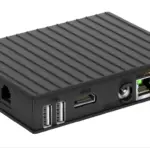
![]() IOT-GATE-iMX8 Industrial Raspberry Pi IoT Gateway
IOT-GATE-iMX8 Industrial Raspberry Pi IoT Gateway
User Guide
IOT-GATE-iMX8 Industrial Raspberry Pi IoT Gateway
© 2023 CompuLab
No warranty of accuracy is given concerning the contents of the information contained in this publication. To the extent permitted by law, no liability (including liability to any person by reason of negligence) will be accepted by CompuLab, its subsidiaries or employees for any direct or indirect loss or damage caused by omissions from or inaccuracies in this document. CompuLab reserves the right to change details in this publication without notice. Product and company names herein may be the trademarks of their respective owners.
CompuLab
17 Ha Yetzira St., Yokneam Illit 2069208, Israel
Tel: +972 (4) 8290100
http://www.compulab.com
Fax: +972 (4) 8325251
Table 1 Document Revision Notes
| Date | Description |
| May 2020 | ·First release |
| June 2020 | ·Added P41 pin-out table in section 5.9 ·Added connector pin numbering in sections 5.4 and 5.10 |
| August 2020 | ·Added industrial I/O add-on sections 3.10 and 5.10 |
| September 2020 | ·Fixed LED GPIO number in section 5.12 |
| February 2021 | ·Removed legacy section |
| October 2021 | ·Updated supported CAN modes in section 3.10.2 ·Fixed antenna connector type in section 5.12 |
| March 2022 | · Added PoE add-on description in sections 3.11 and 5.13 |
| January 2023 | · Added 4–20mA input add-on description in sections 3.10, 3.10.5 and 5.10 · Updated left side panel drawing in section 5.1.3 · Updated digital output wiring diagram in section 3.10.4 · Added digital I/O operating conditions in section 3.10.4 |
| February 2023 | · Added typical power consumption in section 7.3 · Corrected antenna connector assignment table in section 5.12 |
INTRODUCTION
1.1 About This Document
This document is part of a set of documents providing information necessary to operate and program Compulab IOT-GATE-iMX8.
1.2 Related Documents
For additional information not covered in this manual, please refer to the documents listed in Table 2.
Table 2 Related Documents
| Document | Location |
| IOT-GATE-iMX8 design resources | https://www.compulab.com/products/iot-gateways/iot-gate-imx8- industrial-arm-iot-gateway/#devres |
OVERVIEW
2.1 Highlights
- NXP i.MX8M Mini CPU, quad-core Cortex-A53
- Up-to 4GB RAM and 128GB eMMC
- LTE modem, WiFi ac, Bluetooth 5.1
- 2x Ethernet, 3x USB2, RS485 / RS232, CAN-FD
- Custom I/O expansion boards
- Fanless design in aluminum, rugged housing
- Designed for reliability and 24/7 operation
- Wide temperature range of -40C to 80C
- 5 year warranty and 15 year availability
- Wide input voltage range of 8V to 36V
- Debian Linux and Yocto Project
2.2 Specifications
Table 3 CPU, RAM and Storage
| Feature | Specifications |
| CPU | NXP i.MX8M Mini, quad-core ARM Cortex-A53, 1.8GHz |
| Real-Time Co-processor | ARM Cortex-M4 |
| RAM | 1GB – 4GB, LPDDR4 |
| Primary Storage | 4GB – 64GB eMMC flash, soldered on-board |
| Secondary Storage | 16GB – 64GB eMMC flash, optional module |
Table 4 Network
| Feature | Specifications |
| LAN | 1x 1000Mbps Ethernet port, RJ45 connector |
| 1x 100Mbps Ethernet port, RJ45 connector | |
| WiFi | 802.11ac WiFi interface Intel WiFi 6 AX200 module |
| Bluetooth | Bluetooth 5.1 BLE Intel WiFi 6 AX200 module |
| Cellular | 4G/LTE CAT1 cellular module, Simcom SIM7600G * via mini-PCie socket |
| On-board micro-SIM card socket | |
| GNSS | GPS / GLONASS Implemented with Simcom SIM7600G module |
Table 5 I/O and System
| Feature | Specifications |
| PCI Express | Primary mini-PCIe socket, full-size * used for WiFi/BT module when “WB” option is present |
| Secondary mini-PCIe socket, USB only, full-size * used for cellular modem when “JS7600G” option is present |
|
| USB | 3x USB2.0 ports, type-A connectors |
| Serial | 1x RS485 (half-duplex) / RS232 port, terminal-block |
| 1x serial console via UART-to-USB bridge, micro-USB connector | |
| I/O Expansion Module | Up-to 2x CAN-FD / RS485 / RS232, isolated, terminal-block connector |
| 4x digital inputs + 4x digital outputs, isolated, terminal-block connector | |
| Expansion | Expansion connector for add-on boards 2x SPI, 2x UART, I2C, 12x GPIO |
| Security | Secure boot, implemented with i.MX8M Mini HAB module |
| RTC | Real time clock operated from on-board coin-cell battery |
Table 6 Electrical, Mechanical and Environmental
| Supply Voltage | Unregulated 8V to 36V |
| Power Consumption | 2W – 7W, depending on system load and configuration |
| Dimensions | 112 x 84 x 25 mm |
| Enclosure Material | Aluminum housing |
| Cooling | Passive cooling, fanless design |
| Weight | 450 grams |
| MTTF | > 200,000 hours |
| Operation temperature | Commercial: 0° to 60° C Extended: -20° to 60° C Industrial: -40° to 80° C |
CORE SYSTEM COMPONENTS
3.1 NXP I.MX8M Mini Soc
The NXP i.MX8M Mini family of processors features advanced implementation of a quad ARM® Cortex®-A53 core, which operates at speeds of up to 1.8 GHz. A general purpose Cortex®-M4 core processor enables low-power processing.
Figure 1 i.MX8M Mini Block Diagram 
3.2 System Memory
3.2.1 DRAM
IOT-GATE-iMX8 is available with up-to 4GB of on-board LPDDR4 memory.
3.2.2 Primary Storage
IOT-GATE-iMX8 features up-to 64GB of soldered on-board eMMC memory for storing the bootloader andoperating system(kernel androot filesystem). The remaining EMMC space can be used to store general purpose (user) data.
3.2.3 Secondary Storage
IOT-GATE-iMX8 features an optional eMMC module which allows to expand the system non-volatile memory for storing additional data, back-up of the primary storage or installation of a secondary operating system. The eMMC module is installed in socket P14.
3.3 WiFi and Bluetooth
IOT-GATE-iMX8 can be optionally assembled with the Intel WiFi 6 AX200 module providing 2×2 WiFi 802.11ax and Bluetooth 5.1 interfaces.
AX200 module is assembled in mini-PCIe socket #1 (P6).
WiFi / Bluetooth antenna connections are available via RP-SMA connectors on IOT-GATE-iMX8 side panel.
3.4 Cellular and GPS
IOT-GATE-iMX8 cellular interface is implemented with a mini-PCIe modem module and a microSIM socket.
In order to setup IOT-GATE-iMX8 for cellular functionality install an active SIM card into micro-SIM socket P12. The cellular module should be installed into mini-PCIe socket P8.
The cellular modem module also implements GNNS / GPS.
Modem antenna connections are available via RP-SMA connectors on IOT-GATE-iMX8 side panel. CompuLab supplies IOT-GATE-iMX8 with the following cellular modem options:
- 4G/LTE CAT1 module, Simcom SIM7600G (global bands)
Figure 2 service bay – cellular modem  3.5 Ethernet
IOT-GATE-iMX8 incorporates two Ethernet ports:
- ETH1 – primary 1000Mbps port implemented with i.MX8M Mini MAC and Atheros AR8033 PHY
- ETH2 – secondary 100Mbps port implemented with Microchip LAN9514 controller
The Ethernet ports are available on dual RJ45 connector P46.
3.6 USB 2.0
IOT-GATE-iMX8 features three external USB2.0 host ports. The ports are routed to USB connectors P3, P4 and J4. Front panel USB port (J4) is implemented directly with the i.MX8M Mini native USB interface. Back panel ports (P3, P4) are implemented with the on-board USB hub.
3.7 RS485 / RS232
IOT-GATE-iMX8 features a user configurable RS485 / RS232 port implemented with the SP330 transceiver connected to NXP i.MX8M Mini UART port. Port signals are routed to terminal block connector P7.
3.8 Serial Debug Console
IOT-GATE-IMX8 features a serial debug console via UART-to-USB bridge over micro USB connector P5. CP2104 UART-to-USB bridge is interfaced with i.MX8M Mini UART port. CP2104 USB signals are routed to micro USB connector located on the front panel.
3.9 I/O Expansion Socket
IOT-GATE-iMX8 expansion interface is available on M.2 Key-E socket P41. The expansion connector allows to integrate custom I/O add-on boards into IOT-GATE-iMX8. The expansion connector features a set of embedded interfaces such as I2C, SPI, UART and GPIOs. All the interfaces are derived directly from the i.MX8M Mini SoC.
3.10 Industrial I/O add-on
IOT-GATE-iMX8 can be optionally assembled with the industrial I/O add-on board installed into the I/O expansion socket. The industrial I/O add-on features up-to three separate I/O modules which allow to implement different combinations of isolated CAN, RS485, RS232, digital outputs and inputs. The following table shows the supported I/O combinations and ordering codes.
Table 7 Industrial I/O add-on – supported combinations
| Function | Ordering Code | |
| I/O module A | RS232 (rx/tx) | FARS2 |
| RS485 (2-wire) | FARS4 | |
| CAN-FD | FACAN | |
| 4–20mA input | FACL42 | |
| I/O module B | RS232 (rx/tx) | FBRS2 |
| RS485 (2-wire) | FBRS4 | |
| CAN-FD | FBCAN | |
| 4–20mA input | FBCL42 | |
| I/O module C | 4x DI + 4x DO | FCDIO |
Combination examples:
- For 2x RS485 the ordering code will be IOTG-IMX8-…-FARS4-FBRS4-…
- For RS485 + CAN + 4xDI+4xDO ordering code will be IOTG-IMX8-…-FARS4-FBCAN-FCDIO…
For connector details please refer to section 5.10
3.10.1 RS485
RS485 function is implemented with MAX13488 transceiver interfaced with i.MX8M-Mini UART port. Key characteristics:
- 2-wire, half-duplex
- Galvanic isolation from main unit and other I/O modules
- Programmable baud rate of up-to 4Mbps
- Software controlled 120ohm termination resistor
3.10.2 CAN-FD
CAN function is implemented with MCP2518FD controller interfaced with i.MX8M-Mini SPI port.
- Supports CAN 2.0A, CAN 2.0B and CAN FD modes
- Galvanic isolation from main unit and other I/O modules
- Data rate of up to 8Mbps
3.10.3 RS232
RS232 function is implemented with MAX3221 (or compatible) transceiver interfaced with i.MX8MMini UART port. Key characteristics:
- RX/TX only
- Galvanic isolation from main unit and other I/O modules
- Programmable baud rate of up-to 250kbps
3.10.4 Digital inputs and outputs
Four digital inputs are implemented with the CLT3-4B digital termination in accordance with EN 61131-2. Four digital outputs are implemented with the VNI4140K solid state relay in accordance with EN 61131-2. Key characteristics:
- Designed for 24V PLC applicaitons
- Galvanic isolation from main unit and other I/O modules
- Digital outputs maximal output current – 0.5A per channel
Table 8 Digital I/O Operating Conditions
| Parameter | Description | Min | Typ. | Max | Unit |
| 24V_IN | External power supply voltage | 12 | 24 | 30 | V |
| VIN Low | Maximal input voltage recongnized as LOW | 4 | V | ||
| VIN High | Minimal input voltage recognized as HIGH | 6 | V |
Figure 3 Digital output – typical wiring example
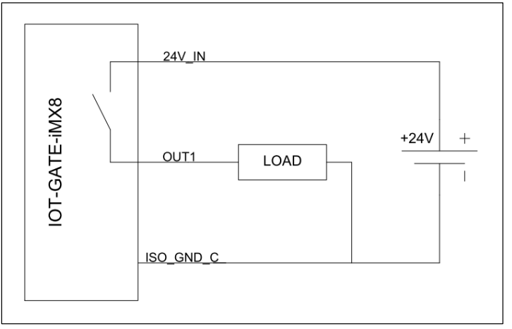 Figure 4 Digital input – typical wiring example
 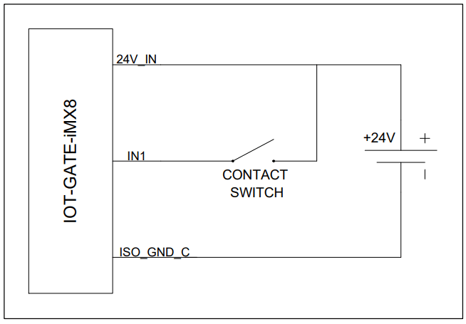 3.10.5 4–20mA input
4–20mA input is implemented with Maxim MAX11108 12-bit ADC.
The ADC is isolated from IOT-GATE-IMX8 main unit. The ADC input circuit is shown in the figure below.
Figure 5 4–20mA input – ADC input circuit 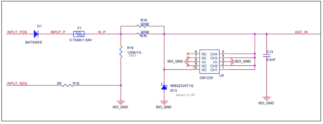 3.11 PoE add-on add-on
IOT-GATE-iMX8 can be optionally assembled with a PoE add-on board installed into the I/O expansion socket. The PoE add-on implements an additional 100Mbit Ethernet port with PoE device capability. When assembled with PoE add-on (configuration option “FPOE”), IOT-GATE-iMX8 can be powered from a POE PSE enabled network cable.
The PoE add-on Ethernet port is implemented using Microchip LAN9500A controller. Equipped with the PoE add-on, IOT-GATE-iMX8 is an IEEE 802.3af class device that can accept up to 13.5W from the network cable. POE PD is implemented with ON semiconductors NCP1090.
NOTE: PoE add-on uses the I/O expansion socket. PoE add-on cannot be combined with the industrial I/O add-on or any other add-on boards.
NOTE: PoE add-on Ethernet controller uses one of the system USB ports. When PoE add-on is present, back panel USB connector P4 is disabled.
SYSTEM LOGIC
4.1 Power Subsystem
4.1.1 Power Rails
IOT-GATE-iMX8 is powered with a single power rail with input voltage range of 8V to 36V.
4.1.2 Power Modes
IOT-GATE-iMX8 supports two hardware power modes.
Table 9 Power modes
| Power Mode | Description |
| ON | All internal power rails are enabled. Mode entered automatically when main power supply is connected. |
| OFF | i.MX8M Mini core power rails are off, most of the peripherals power rails are off. |
4.1.3 RTC Back-Up Battery
IOT-GATE-iMX8 features a 120mAh coin cell lithium battery, which maintains the on-board RTC whenever the main power supply is not present.
4.2 Real Time Clock
The IOT-GATE-iMX8 RTC is implemented with the AM1805 real time clock (RTC). The RTC is connected to the i.MX8M SoC using I2C2 interface at address 0xD2/D3. IOT-GATE-iMX8 backup battery keeps the RTC running to maintain clock and time information whenever the main power supply is not present.
INTERFACES AND CONNECTORS
5.1 Connector Locations
5.1.1 Front Panel 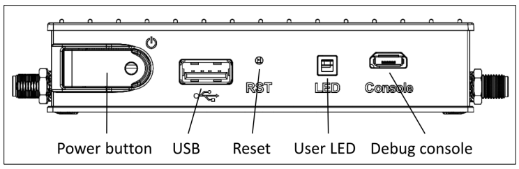 5.1.2 Back Panel
 5.1.3 Left Side Panel
 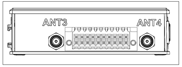 5.1.4 Right Side Panel
 5.1.5 Service Bay
 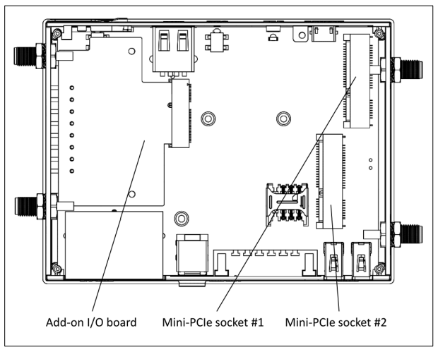 5.2 DC Power Jack (J1)
DC power input connector.
Table 10 J1 connector pin-out
| Pin | Signal Name | |
| 1 | DC IN | |
| 2 | GND | |
Table 11 J1 connector data
| Manufacturer | Mfg. P/N |
| Contact Technology | DC-081HS(-2.5) |
The connector is compatible with the IOT-GATE-iMX8 power supply unit available from CompuLab.
5.3 USB Host Connectors (J4, P3, P4)
The IOT-GATE-iMX8 external USB2.0 host ports are available through three standard type-A USB connectors (J4, P3, P4). For additional details, please refer to section 3.6 of this document.
5.4 RS485 / RS232 Connector (P7)
IOT-GATE-iMX8 features configurable RS485 / RS232 interface routed to terminal block P7. RS485 / RS232 operation mode is controlled in software. For additional details please refer to IOT-GATEiMX8 Linux documentation.
Table 12 P7 connector pin-out
| Pin | RS485 mode | RS232 mode | Pin numbering |
| 1 | RS485_NEG | RS232_TXD |
|
| 2 | RS485_POS | RS232_RTS | |
| 3 | GND | GND | |
| 4 | NC | RS232_CTS | |
| 5 | NC | RS232_RXD | |
| 6 | GND | GND |
5.5 Serial Debug Console (P5)
The IOT-GATE-iMX8 serial debug console interface is routed to micro USB connector P5. For more information, please refer to section 3.8 of this documents.
5.6 RJ45 Dual Ethernet Connector (P46)
The IOT-GATE-iMX8 two Ethernet ports are routed to dual RJ45 connector P46. For additional details, please refer to section 3.5 of this document.
5.7 USIM socket (P12)
The uSIM socket (P12) is connected to mini-PCIe socket P8.
5.8 Mini-PCIe Sockets (P6, P8)
IOT-GATE-iMX8 features two mini-PCIe sockets (P6, P8) which implement different interfaces and are intended to different functions.
- Mini-PCie socket #1 is mainly intended for WiFi modules that require PCIe interface
- Mini-PCIe socket #2 is mainly intended for cellular modems and LORA modules
Table 13 mini-PCIe socket interfaces
| Interface | mini-PCIe socket #1 (P6) | mini-PCIe socket #2 (P8) |
| PCIe | Yes | No |
| USB | Yes | Yes |
| SIM | No | Yes |
NOTE: Mini-PCIe socket #2 (P8) does not feature PCIe interface.
5.9 I/O Expansion Connector (P41)
IOT-GATE-iMX8 I/O expansion connector P41 allows to connect add-on boards to IOT-GATE-iMX8.
Some of the P41 signal are derived from i.MX8M Mini multifunctional pins. The following table outlines the connector pin-out and available pin functions.
NOTE: Multifunctional pin function selection is controlled in software.
NOTE: Each multifunctional pin can be used for a single function at a time.
NOTE: Only one pin can be used for each function (in case a function is available on more than one carrier board interface pin).
Table 14 P41 connector pin-out
| Pin | Singal name | Description |
| 1 | GND | IOT-GATE-iMX8 common ground |
| 2 | VCC_3V3 | IOT-GATE-iMX8 3.3V power rail |
| 3 | EXT_HUSB_DP3 | Optional USB port positive data signal. Multiplexed with back-panel connector P4 |
| 4 | VCC_3V3 | IOT-GATE-iMX8 3.3V power rail |
| 5 | EXT_HUSB_DN3 | Optional USB port negative data signal. Multiplexed with back-panel connector P4. |
| 6 | RESERVED | Reserved for future use. Must be left unconnected |
| 7 | GND | IOT-GATE-iMX8 common ground |
| 8 | RESERVED | Reserved for future use. Must be left unconnected |
| 9 | JTAG_NTRST | Processor JTAG interface. Test reset signal. |
| 10 | RESERVED | Reserved for future use. Must be left unconnected. |
| 11 | JTAG_TMS | Processor JTAG interface. Test mode select signal. |
| 12 | VCC_SOM | IOT-GATE-iMX8 3.7V power rail |
| 13 | JTAG_TDO | Processor JTAG interface. Test data out signal. |
| 14 | VCC_SOM | IOT-GATE-iMX8 3.7V power rail |
| 15 | JTAG_TDI | Processor JTAG interface. Test data in signal. |
| 16 | RESERVED | Reserved for future use. Must be left unconnected. |
| 17 | JTAG_TCK | Processor JTAG interface. Test clock signal. |
| 18 | RESERVED | Reserved for future use. Must be left unconnected. |
| 19 | JTAG_MOD | Processor JTAG interface. JTAG mode signal. |
| 20 | RESERVED | Reserved for future use. Must be left unconnected. |
| 21 | VCC_5V | IOT-GATE-iMX8 5V power rail |
| 22 | RESERVED | Reserved for future use. Must be left unconnected. |
| 23 | VCC_5V | IOT-GATE-iMX8 5V power rail |
| 32 | RESERVED | Reserved for future use. Must be left unconnected. |
| 33 | QSPIA_DATA3 | Multifunctional signal. Available functions: QSPIA_DATA3, GPIO3_IO[9] |
| 34 | RESERVED | Reserved for future use. Must be left unconnected. |
| 35 | QSPIA_DATA2 | Multifunctional signal. Available functions: QSPI_A_DATA2, GPIO3_IO[8] |
| 36 | ECSPI2_MISO/UART4_CTS | Multifunctional signal. Available functions: ECSPI2_MISO, UART4_CTS, GPIO5_IO[12] |
| 37 | QSPIA_DATA1 | Multifunctional signal. Available functions: QSPI_A_DATA1, GPIO3_IO[7] |
| 38 | ECSPI2_SS0/UART4_RTS | Multifunctional signal. Available functions: ECSPI2_SS0, UART4_RTS, GPIO5_IO[13] |
| 39 | QSPIA_DATA0 | Multifunctional signal. Available functions: QSPI_A_DATA0, GPIO3_IO[6] |
| 40 | ECSPI2_SCLK/UART4_RX | Multifunctional signal. Available functions: ECSPI2_SCLK, UART4_RXD, GPIO5_IO[10] |
| 41 | QSPIA_NSS0 | Multifunctional signal. Available functions: QSPI_A_SS0_B, GPIO3_IO[1] |
| 42 | ECSPI2_MOSI/UART4_TX | Multifunctional signal. Available functions: ECSPI2_MOSI, UART4_TXD, GPIO5_IO[11] |
| 43 | QSPIA_SCLK | Multifunctional signal. Available functions: QSPI_A_SCLK, GPIO3_IO[0] |
| 44 | VCC_SOM | IOT-GATE-iMX8 3.7V power rail |
| 45 | GND | IOT-GATE-iMX8 common ground |
| 46 | VCC_SOM | IOT-GATE-iMX8 3.7V power rail |
| 47 | DSI_DN3 | MIPI-DSI, data diff-pair #3 negative |
| 48 | I2C4_SCL_CM | Multifunctional signal. Available functions: I2C4_SCL, PWM2_OUT, GPIO5_IO[20] |
| 49 | DSI_DP3 | MIPI-DSI, data diff-pair #3 positive |
| 50 | I2C4_SDA_CM | Multifunctional signal. Available functions: I2C4_SDA, PWM1_OUT, GPIO5_IO[21] |
| 51 | GND | IOT-GATE-iMX8 common ground |
| 52 | SAI3_TXC | Multifunctional signal. Available functions: GPT1_COMPARE2, UART2_TXD, GPIO5_IO[0] |
| 53 | DSI_DN2 | MIPI-DSI, data diff-pair #2 negative |
| 54 | SAI3_TXFS | Multifunctional signal. Available functions: GPT1_CAPTURE2, UART2_RXD, GPIO4_IO[31] |
| 55 | DSI_DP2 | MIPI-DSI, data diff-pair #2 positive |
| 56 | UART4_TXD | Multifunctional signal. Available functions: UART4_TXD, UART2_RTS, GPIO5_IO[29] |
| 57 | GND | IOT-GATE-iMX8 common ground |
| 58 | UART2_RXD/ECSPI3_MISO | Multifunctional signal. Available functions: UART2_RXD, ECSPI3_MISO, GPIO5_IO[24] |
| 59 | DSI_DN1 | MIPI-DSI, data diff-pair #1 negative |
| 60 | UART2_TXD/ECSPI3_SS0 | Multifunctional signal. Available functions: UART2_TXD, ECSPI3_SS0, GPIO5_IO[25] |
| 61 | DSI_DP1 | MIPI-DSI, data diff-pair #1 positive |
| 62 | RESERVED | Reserved for future use. Must be left unconnected. |
| 63 | GND | IOT-GATE-iMX8 common ground |
| 64 | RESERVED | Reserved for future use. Must be left unconnected. |
| 65 | DSI_DN0 | MIPI-DSI, data diff-pair #0 negative |
| 66 | UART4_RXD | Multifunctional signal. Available functions: UART4_RXD, UART2_CTS, GPIO5_IO[28] |
| 67 | DSI_DP0 | MIPI-DSI, data diff-pair #0 positive |
| 68 | ECSPI3_SCLK | Multifunctional signal. Available functions: ECSPI3_SCLK, GPIO5_IO[22] |
| 69 | GND | IOT-GATE-iMX8 common ground |
| 70 | ECSPI3_MOSI | Multifunctional signal. Available functions: ECSPI3_MOSI, GPIO5_IO[23] |
| 71 | DSI_CKN | MIPI-DSI, clock diff-pair negative |
| 72 | EXT_PWRBTNn | IOT-GATE-iMX8 ON/OFF signal |
| 73 | DSI_CKP | MIPI-DSI, clock diff-pair positive |
| 74 | EXT_RESETn | IOT-GATE-iMX8 cold reset signal |
| 75 | GND | IOT-GATE-iMX8 common ground |
5.10
Industrial I/O add-on board
Table 15 Industrial I/O add-on connector pin-out
| I/O module | Pin | Singal |
| A | 1 | RS232_TXD / RS485_POS / CAN_H / 4-20_mA_IN+ |
| 2 | ISO_GND_A | |
| 3 | RS232_RXD / RS485_NEG / CAN_L | |
| 4 | NC | |
| 5 | 4-20_mA_IN- | |
| B | 6 | 4-20_mA_IN- |
| 7 | RS232_TXD / RS485_POS / CAN_H / 4-20_mA_IN+ | |
| 8 | ISO_GND_B | |
| 9 | RS232_RXD / RS485_NEG / CAN_L | |
| 10 | NC | |
| C | 11 | OUT0 |
| 12 | OUT2 | |
| 13 | OUT1 | |
| 14 | OUT3 | |
| 15 | IN0 | |
| 16 | IN2 | |
| 17 | IN1 | |
| 18 | IN3 | |
| 19 | 24V_IN | |
| 20 | ISO_GND_C |
Table 16 Industrial I/O add-on connector data
| Connector type | Pin numbering |
| P/N: Kunacon PDFD25420500K 20-pin dual-raw plug with push-in spring connections Locking: screw flange Pitch: 2.54 mm Wire cross section: AWG 20 – AWG 30 |
5.11 Indicator LEDs
The tables below describes IOT-GATE-iMX8 indicator LEDs.
Table 17 Power LED (DS1)
| Main power connected | LED state |
| Yes | On |
| No | Off |
Table 18 User LED (DS4)
General purpose LED (DS4) is controlled by SoC GPIOs GP3_IO19 and GP3_IO25.
| GP3_IO19 state | GP3_IO25 state | LED state |
| Low | Low | Off |
| Low | High | Green |
| High | Low | Yellow |
| High | High | Orange |
5.12 Antenna Connectors
IOT-GATE-iMX8 features up-to four RP-SMA connectors for external antennas.
Table 19 Default antenna connector assignment
| Connector | Function |
| ANT1 | WiFi-A / BT antenna |
| ANT2 | WiFi-B antenna |
| ANT3 | Modem GNSS antenna |
| ANT4 | Modem MAIN antenna |
5.13 PoE add-on RJ45 Ethernet Connector
The IOT-GATE-iMX8 PoE add-on Ethernet port is routed to standard RJ45 connector on the left side panel. For additional details, please refer to section 3.11 of this document.
MECHANICAL DRAWINGS
IOT-GATE-iMX8 3D model is available for download at:
https://www.compulab.com/products/iot-gateways/iot-gate-imx8-industrial-arm-iot-gateway/#devres
OPERATIONAL CHARACTERISTICS
7.1 Absolute Maximum Ratings
Table 20 Absolute Maximum Ratings
| Parameter | Min | Max | Unit |
| Main power supply voltage | -0.3 | 40 | V |
7.2 Recommended Operating Conditions
Table 21 Recommended Operating Conditions
| Parameter | Min | Typ. | Max | Unit |
| Main power supply voltage | 8 | 12 | 36 | V |
7.3 Typical Power Consumption
Table 22 IOT-GATE-iMX8 Typical Power Consumption
| Use case | Use case description | Current | Power |
| Linux idle | Linux up, Ethernet up, no activity | 220mA | 2.6W |
| Wi-Fi or Ethernet data transfer | Linux up + active ethernet or Wi-Fi data transmission | 300mA | 3.6W |
| Cellular modem data transfer | Linux up +active modem data transmission | 420mA | 5W |
| Heavy mixed load without cellular activity | CPU and memory stress-test + Wi-Fi running + Bluetooth running + Ethernet activity + LEDs |
400mA |
4.8W |
| Heavy mixed load with active cellular modem data transfer | CPU and memory stress-test + active modem data transmission |
600mA |
7.2W |
Power consumption has been measured with the following setup:
- Configuration – IOTG-IMX8-D4-NA32-WB-JS7600G-FARS4-FBCAN-PS-XL
- Standard IOT-GATE-IMX8 12VDC PSU
- Software stack – stock Debian (Bullseye) for IOT-GATE-iMX8 v3.1.2
![]()
Documents / Resources
 |
CompuLab IOT-GATE-iMX8 Industrial Raspberry Pi IoT Gateway [pdf] User Guide IOT-GATE-iMX8 Industrial Raspberry Pi IoT Gateway, IOT-GATE-iMX8, Industrial Raspberry Pi IoT Gateway, Raspberry Pi IoT Gateway, Pi IoT Gateway |