COMPEX WLW7000E6 WiFi 7 Single Band Module

Hardware Guide – WLW7000E6
Component Map
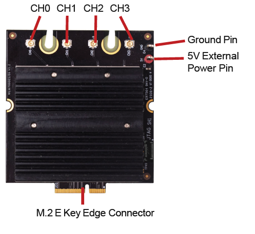
Power Requirements
DC Power 5V
Power Consumption 14W (Max)
- For the customer who want to use 5V External Power Pin, please make sure pins 15, 17, 19, 21 and 23 were not connected with your board.
- For pins 52, 53 and 55 support either 1.8V or 3.3V. However, it’s important to note that you can only select one voltage option for these pins.
- * Default voltage for pins 52, 53 and 55 is 1.8V.
M.2 Edge Connector Pin Assignment
| M.2 edge connector pin assignment | |||
| Top side | Bottom side | ||
| 1 | GND | 2 | VDD_3V3 |
| 3 | REFCLK_IO_P0 | 4 | VDD_3V3 |
| 5 | REFCLK_IO_N0 | 6 | PCIE_LED0(GPIO25) |
| 7 | GND | 8 | NC |
| 9 | NC | 10 | NC |
| 11 | NC | 12 | NC |
| 13 | NC | 14 | WSI_DAT_OUT(GPIO48) |
| 15 | VDD_5V | 16 | PCIE_LED1(GPIO26) |
| 17 | VDD_5V | 18 | GND |
| 19 | VDD_5V | 20 | WSI_CLK_OUT(GPIO49) |
| 21 | VDD_5V | 22 | NC |
| 23 | VDD_5V | ||
| Mechanical key E | |||
| 33 | GND | 32 | WSI_DAT_IN(GPIO50) |
| 35 | PCIE0_RX0_P | 34 | NC |
| 37 | PCIE0_RX0_N | 36 | WSI_CLK_IN(GPIO51) |
| 39 | GND | 38 | NC |
| 41 | PCIE0_TX0_P | 40 | NC |
| 43 | PCIE0_TX0_N | 42 | NC |
| 45 | GND | 44 | PTA1_BT_PRIO |
| 47 | PCIE0_REFCLK_P | 46 | PTA1_WL_ACT |
| 49 | PCIE0_REFCLK_N | 48 | PTA1_BT_ACT |
| 51 | GND | 50 | NC |
| 53 | PCIE0_CLKREQ_N | 52 | PCIE0_RST_N |
| 55 | PCIE0_WAKE_N | 54 | NC |
| 57 | GND | 56 | WLAN_DISABLE |
| 59 | PCIE0_RX1_P | 58 | NC |
| 61 | PCIE0_RX1_N | 60 | NC |
| 63 | GND | 62 | NC |
| 65 | PCIE0_TX1_P | 64 | NC |
| 67 | PCIE0_TX1_N | 66 | NC |
| 69 | GND | 68 | NC |
| 71 | REFCLK_IO_N1 | 70 | NC |
| 73 | REFCLK_IO_P1 | 72 | VDD_3V3 |
| 75 | GND | 74 | VDD_3V3 |
Copyright © Compex Systems. All rights reserved. COMPEX and the COMPEX logo, are registered trademarks of Compex Systems Pte. Ltd. While every effort is made to ensure the information is accurate, Compex does not accept liability for any errors or mistakes that may arise. All specifications are subject to change without notice.
Compex Systems Pte Ltd | www.compex.com.sg | (+65) 6288 8220 | sales@compex.com.sg | Last Updated: 21/11/2024
MW, HJ, GS, YX
FAQ
- Q: What should I do if I want to use the 5V External Power Pin?
A: To use the 5V External Power Pin, ensure that pins 15, 17, 19, 21, and 23 are not connected to your board. - Q: Can I select both 1.8V and 3.3V for pins 52, 53, and 55?
A: No, you can only select one voltage option for pins 52, 53, and 55.
Documents / Resources
 |
COMPEX WLW7000E6 WiFi 7 Single Band Module [pdf] Instructions WLW7000E6, QCN6274, QCN9274, WLW7000E6 WiFi 7 Single Band Module, WLW7000E6, WiFi 7 Single Band Module, Single Band Module, Band Module, Module |