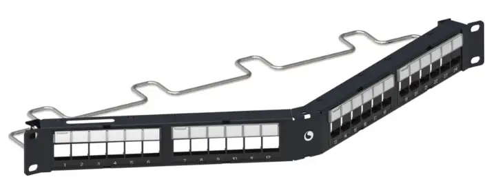
COMMSCOPE CPP-UDDM-SL-1U-24 Unshielded Discrete Distribution Module
Specifications
- Material ID: 760237040
- Part No.: CPP-UDDM-SL-1U-24
- Description: Unshielded Discrete Distribution Module Panel, SL, 1U, 24 port, Black
General
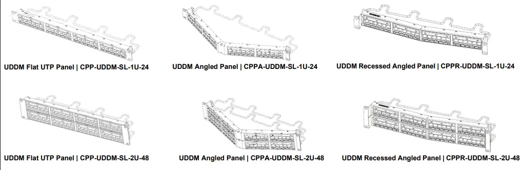
The CommScope® Unshielded discrete distribution module (UDDM) panels are available in a 24 port or 48 port, flat, angled or recessed angled configuration.
The panel consists of a rack mounted base unit, rear cable management, labels for port numbering, hardware kit and hook and loop straps. Each panel mounts in a 19-inch (483mm) equipment rack with universal hole spacing. Ordering information is listed below:
| Material ID | Part No. | Description |
| 760237040 | CPP-UDDM-SL-1U-24 | Unshielded Discrete Distribution Module Panel, SL, 1U, 24 port, Black |
| 760237041 | CPP-UDDM-SL-2U-48 | Unshielded Discrete Distribution Module Panel, SL, 2U, 48 port, Black |
| 760237042 | CPPA-UDDM-SL-1U-24 | Unshielded Angled Discrete Distribution Module Panel, SL, 1U, 24 port, Black |
| 760237043 | CPPA-UDDM-SL-2U-48 | Unshielded Angled Discrete Distribution Module Panel, SL, 2U, 48 port, Black |
| 760237044 | CPPR-UDDM-SL-1U-24 | Unshielded Recessed Angled Discrete Distribution Module Panel, SL, 1U, 24 port, Black |
| 760237045 | CPPR-UDDM-SL-2U-48 | Unshielded Recessed Angled Discrete Distribution Module Panel, SL, 2U, 48 port, Black |
| 760237052 | CPP-UDDM-KJ-1U-24 | Unshielded Discrete Distribution Module Panel, Keystone, 1U, 24 port, Black |
| 760241547 | CPP-UDDM-KJ-2U-48 | Unshielded Discrete Distribution Module Panel, Keystone, 2U, 48 port, Black |
| 760250319 | CPPA-UDDM-KJ-1U-24-WH | Unshielded Angled Discrete Distribution Module Panel, Keystone, 1U, 24 port, White |
| 760250320 | CPPA-UDDM-KJ-2U-48-WH | Unshielded Angled Discrete Distribution Module Panel, Keystone, 2U, 48 port, White |
| 760253047 | CPPA-UDDM-KJ-1U-24 | Unshielded Angled Discrete Distribution Module Panel, Keystone, 1U, 24 port, Black |
| 760253048 | CPPA-UDDM-KJ-2U-48 | Unshielded Angled Discrete Distribution Module Panel, Keystone, 2U, 48 port, Black |
Note: sample product images are shown below for reference.
 Tools Required
- Phillips head screwdriver.
- Flat blade screwdriver, max 2.9mm dia.
Parts List
Verify parts against parts list below:
|
24-Port Flat Panel |
48-Port Flat Panel |
Quantity
24-Port 48-Port Ang Panel Ang panel |
24-Port R-Ang Panel |
48-Port R-Ang Panel |
Description | |
| 1 | ― | ― | ― | ― | ― | 24-port flat panel |
| ― | 1 | ― | ― | ― | ― | 48-port flat panel |
| ― | ― | 1 | ― | ― | ― | 24-port angled panel |
| ― | ― | ― | 1 | ― | ― | 48-port angled panel |
| ― | ― | ― | ― | 1 | ― | 24-port recessed angled panel |
| ― | ― | ― | ― | ― | 1 | 48-port recessed angled panel |
| 1 | 1 | 1 | 1 | 1 | 1 | P12-24 x ½” mounting screw kit |
| 1 | 2 | 1 | 2 | 1 | 2 | Label holder kit |
| 1 | 2 | 1 | 2 | 1 | 2 | Rear cable management |
| 1 | 2 | 1 | 2 | 1 | 2 | Hook-and-loop straps kit |
WARNING – Important Safety Instructions
When using this product, the following basic safety precautions should be followed to reduce the risk of fire, electric shock, and injury to persons:
- Never install communications wiring in wet locations unless it is designed for wet locations.
- Never install this product during a lightning storm. There is a remote risk of electric shock.
- Never touch uninsulated communication wiring or terminals unless the communication circuit has been disconnected at the network interface.
- Caution: All wiring that connects to this equipment must meet applicable local and national building codes and network wiring standards for communication cable.
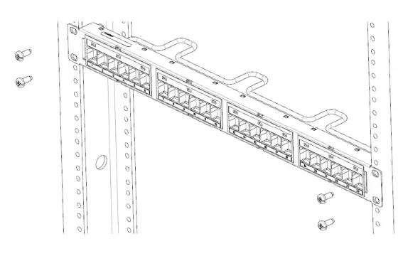
Installation of Panel
Step 1 – Mount Panel to Rack
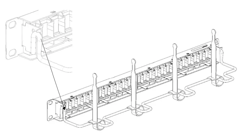
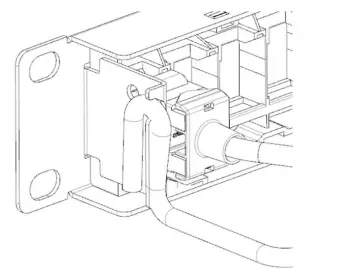
Step 2 – Assemble Rear Cable Management and Other Accessories
Attach rear cable management as shown and insert four hook-and-loop straps to the rear cable management.
Step 3 – Populate Panel with Jacks (Jacks ordered separately)
 24-Port Panel
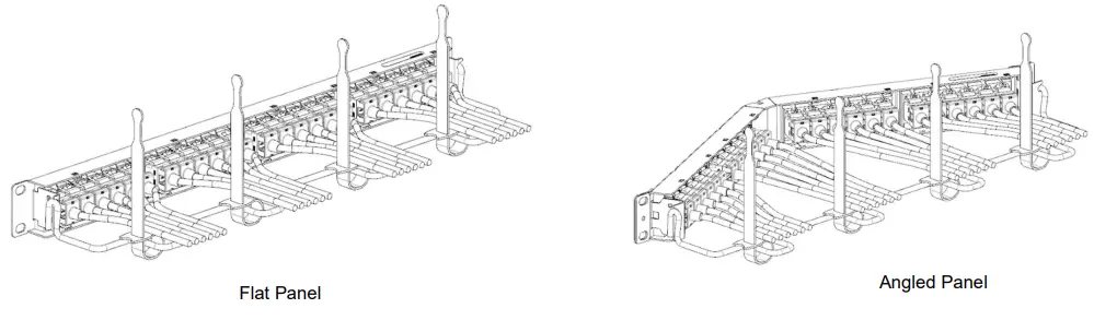
- Connect cables to jacks per instructions provided with the individual jacks.
- Populate panel with jacks and route cabling as shown.
Note: Secure cables using the hook-and-loop straps provided.
Step 4 – Attaching Information Labels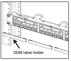
- Enter information on the white information labels provided in label holder kits. Snap holders into panel modules and insert labels into label holders as shown in the above image.
- To print a designation label
- Go to http://www.commscope.com/Resources/Labeling-Templates and scroll down to “Copper Panels” and select the proper label template. Or go to https://www.commscope.com/ and search individual part number (material ID).
- Select the part number and scroll down to the “documentation and downloads” section. In the template section, select the required label size.
Note: Labeling website has two options for printing labels; letter size and A4 size.
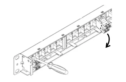
- Insert a small, 2.9mm dia. max flat-blade screwdriver into the slot above the jack and rotate to release the latch.
- Remove jack from rear of panel.
- Note – rear cable management may need to be removed to enable access to the release slot on some jack positions.
Trade–marks
All trademarks identified by ® or ™ are registered trademarks or trademarks, respectively, of CommScope, Inc. This document is for planning purposes only and is not intended to modify or supplement any specifications or warranties relating to CommScope products or services. CommScope is committed to the highest standards of business integrity and environmental sustainability, with a number of CommScope’s facilities across the globe certified in accordance with international standards, including ISO 9001, TL 9000, and ISO 14001.
Further information regarding CommScope’s commitment can be found at: https://www.commscope.com/corporate-responsibility-and-sustainability/.
Contact information
Visit our website or contact your local CommScope representative for more information.
For technical assistance, customer service, or to report any missing/damaged parts, visit us at: http://www.commscope.com/SupportCenter Or Contact PartnerPRO Network Partner https://www.commscope.com/partners/
This product may be covered by one or more U.S. patents or their foreign equivalents. For patents, see www.cs-pat.com
Safety Precautions
When using this product, follow these safety precautions to reduce the risk of fire, electric shock, and injury:
- Never install communications wiring in wet locations unless designed for wet areas.
- Avoid installation during lightning storms due to the risk of electric shock.
- Avoid touching uninsulated communication wiring or terminals unless disconnected at the network interface.
- Ensure all wiring connected to the equipment meets local and national building codes and network wiring standards.
FAQ’s
Are these panels suitable for outdoor use?
No, it is recommended to avoid installing communications wiring in wet locations unless specifically designed for such environments.
What tools are required for installation?
You will need a Phillips head screwdriver and a flat blade screwdriver with a maximum diameter of 2.9mm.
Documents / Resources
 |
COMMSCOPE CPP-UDDM-SL-1U-24 Unshielded Discrete Distribution Module [pdf] Installation Guide CPP-UDDM-SL-1U-24, CPP-UDDM-SL-2U-48, CPPA-UDDM-SL-1U-24, CPPA-UDDM-SL-2U-48, CPPR-UDDM-SL-1U-24, CPPR-UDDM-SL-2U-48, CPP-UDDM-SL-1U-24 Unshielded Discrete Distribution Module, CPP-UDDM-SL-1U-24, Unshielded Discrete Distribution Module, Discrete Distribution Module, Distribution Module |