![]()
CLA-VAL CV-Log-35
Communicating Data Logger
User Manual
INTRODUCTION
1.1 PRECAUTIONS BEFORE STARTING
![]() Installation and electrical connection should be carried out in accordance with local regulations and only by qualified technicians!
Installation and electrical connection should be carried out in accordance with local regulations and only by qualified technicians!
![]() The protection level is guaranteed only if product has been installed by technicians instructed by CLA-VAL personnel and thereafter correctly maintained. During installation and maintenance, the inside of product must remain completely dry.
The protection level is guaranteed only if product has been installed by technicians instructed by CLA-VAL personnel and thereafter correctly maintained. During installation and maintenance, the inside of product must remain completely dry.
Humidity may drastically shorten the life of the battery and electronics.
1.2 BATTERY
![]() Do not connect or disconnect the battery of the product in hazardous locations such as a damp room.
Do not connect or disconnect the battery of the product in hazardous locations such as a damp room.
![]() Using batteries other than those supplied by CLA-VAL may lead to a risk of explosion and void the product warranty.
Using batteries other than those supplied by CLA-VAL may lead to a risk of explosion and void the product warranty.
The battery provided with the product is not rechargeable and must be disposed properly at end of life.
1.3 GENERAL DISCLAIMER
In accordance with our policy of continuous development and improvement, CLA-VAL reserves the right to modify or improve these products at any time without prior notice. CLA-VAL assumes no liability or responsibility for any errors or omissions in the content of this document.
1.4 ENVIRONMENTAL PROTECTION
The product is delivered with batteries marked with this symbol ![]() .
.
Help to preserve and protect the environment. Recycle used batteries and accessories; this means that according to local laws and regulations, they should be disposed of separately from household waste.
1.5 TYPOGRAPHY
Throughout this manual, the following typographical conventions and symbols have been adopted to help readability:
a. “Bold”: Menu, command, tab and button
b. BOLD ITALIC: Important information
c. (1) or (A): Circled numbers and letters in the text refer to the parts described in Figure 1 and 2 respectively (example: Figure 1 – page 5)
d. ![]() Note: Indicates useful information and advice
Note: Indicates useful information and advice
e. ![]() : Indicates safety advice that must be strictly followed
: Indicates safety advice that must be strictly followed
1.6 ACRONYMS
LED: Light Emitting Diode
NCR: Notification Claim Return
SMS: Short Messages Service
GPRS: General Packet Radio Service
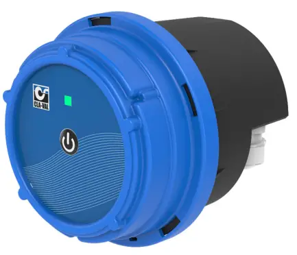
CV-LOG-35 CHARACTERISTICS
- Body
- Head (main board + front panel)
- Antenna (optional)

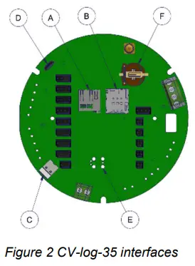
(A) SIM Card connector
(B) SD Card connector
(C) Battery connector
(D) Micro USB Connector
(E) Tag connect (8 pin)
(F) Memory battery coin holder coin
WIRING CHARACTERISTICS
Refer to the CVLog3500 wiring diagram for connection details.
SENSOR MOUNTING
4.1 PRESSURE SENSORS
The pressure sensors can be mounted either vertically or horizontally.

4.2 METER WITH PULSE EMITTER
Any pulse emitter may be connected to the CV-Log-35 counter input if its electrical system has either a “Normally Open” or “Normally Closed” contact. For setting up the pulse emitter, refer to the meter manufacturer’s instructions and the CV-Log-35 instructions located in the CVLog3500 wiring diagram.
![]() Note:
Note:
- Always connect meter last to avoid arbitrary pulse counts.
- In any case you can reset the counter from the user interface.
CV-LOG-35 MOUNTING
![]() When mounting a CV-Log-35 with sensors other than those provided by CLA-VAL, be careful not to damage or deform the housing in any way (warranty will become void).
When mounting a CV-Log-35 with sensors other than those provided by CLA-VAL, be careful not to damage or deform the housing in any way (warranty will become void).
5.1 CELLULAR NETWORK QUALITY
Check the cellular network quality at the installation location prior to installing the product.
Network strength indication from a cell phone gives initial information about signal reception quality on a site. For more accurate information, use the CV-Log-35 configuration mode to get the exact reception quality of the product. Refer to chapter 9.11 « Checking the quality of the network » for more details.
The CV-Log-35 configuration mode will indicate (amongst other things), the network reception quality as seen by the CV-Log-35 in dBm units. Installation is not recommended for signal quality under -95 dBm. As the cellular network quality may fluctuate strongly across the site, it is recommended to test at different locations.
If network quality at the installed location is not sufficient, it may be necessary to relocate the CV-Log-35 or extend its antenna with adequate CLA-VAL extension cables.
The minimum signal strength is – 80 dBm for optimum data communication at the valve level.
5.1.1 NETWORK QUALITY BETWEEN -80 dBm and -95 dBm
If the signal quality at the valve level is between -80 dBm and -95 dBm, check if the CV-Log-35 can be installed closer to the well opening, while maintaining a maximum distance of 3 m to the pressure sensors. If this is not possible, an antenna extension with optional CLA-VAL antenna extension cables might be necessary.
5.1.2 NETWORK QUALITY LESS THAN -95 dBm
If the signal quality at the valve level is lower than -95 dBm, it is required to deport the antenna outside of the well.
Please contact CLA-VAL for more information.
5.2 ORIENTATION IN SPACE
CV-Log-35 should be mounted in an upright position (antenna side up, cable gland down) to guarantee good cellular connectivity.
CV-Log-35 may have difficulties transmitting when submerged (e.g. in a manhole after rainfall).
To guarantee reliable transmission it is recommended to install it as high as possible in the well.

5.3 WALL MOUNTED INSTALLATION

CV-Log-35 can be fixed on walls using the wall mounted bracket.
Drill the holes at the correct distance (72 mm) or use the lower housing as a drilling gauge.
5.3.1 DIN RACK MOUNTED INSTALLATION
 An alternative optional bracket is available for electrical box installation.
5.3.2 ORIENTABLE BRACKET INSTALLATION
 An optional orientable wall-mounted or valve bracket for CV-Log-35 is also available.
 5.3.3 STRANDARD INSTALLATION
 The standard installation of the CV-Log-35 on the wall should be, as close as possible to the well opening, but not further than 3 m from the pressure sensor(s) connection(s) on the valve.
CONNECTION
6.1 PULSE COUNTING
![]() Note:
Note:
Refer to the meter manufacturer’s product information for complete information about functionality and connectivity.
The counter contact (“Normally Open” or “Normally Closed”) must be connected between Tx/Cnt and GND (refer to CVLog3500 wiring diagram).
SIM CARD
7.1 PREPARING THE SIM CARD
A 3FF/Micro-SIM format is necessary for data communication compatible with LTE cat-M1, NB-IoT, or GPRS. CLA-VAL can optionally provide a SIM card. If another SIM card than the one supplied by CLA-VAL is used refer to chapter 9.10 « Custom SIM Card » for configuration.
7.2 INSERTING THE SIM CARD
Insert the SIM card with the golden contacts facing downwards into the card holder. Refer to Figure 2 – Chapter 2 « CV-Log-35 Characteristics » and the symbol printed on the CV-Log-35 for correct SIM card orientation. The SIM card must be completely inserted into the card holder. If the card is overlapping the card holder after insertion, remove it and check the card’s orientation.
![]() Avoid touching the metal contacts to prevent grease buildup. If touched, clean them with a dry cloth or a cotton swab lightly moistened with isopropyl alcohol, then allow to dry before insertion.
Avoid touching the metal contacts to prevent grease buildup. If touched, clean them with a dry cloth or a cotton swab lightly moistened with isopropyl alcohol, then allow to dry before insertion.
STARTING OPERATION
8.1 CV-LOG-35 ASSEMBLY
![]() If the product has been opened before closing, ensure the inside of the housing and seal are clean and dry. The presence of dust or humidity when installing may damage the product.
If the product has been opened before closing, ensure the inside of the housing and seal are clean and dry. The presence of dust or humidity when installing may damage the product.
- Connect the antenna (3) to the product (if present) (1).
- Insert the SIM card in the base (if present) (B).
- Close the body (1) by rotating the head (2), see Figure 3 below.
 Do not force closure! If the two parts of the housing cannot be fit together properly, make sure there is no pinched cable or dust.

8.2 OPERATING MODE
The CV-Log-35 has 3 modes of operation:
- “Standby” mode
- “Acquisition” mode
- “Configuration” mode
In “Standby” mode you can remove the SIM card or SD card, as well as connect or disconnect physical inputs.
The “Acquisition” mode is the operating mode of the CV-Log-35. In this mode, the device acquires the signals from the connected sensors and saves them to the internal memory. If the data communication option is enabled, the recorded data is sent across the cellular network at the set interval time.
The “Configuration” mode is used to activate the WiFi local network generated by the device, to configure the CV-Log-35.

8.3 ACTIVATING CV-LOG-35
Once the following actions are performed
- Connected the battery & installed the sensor.
- Inserted the SIM card (if not using the default CLA-VAL SIM card)
- Closed the housing.
Switch to “Acquisition” mode on your CV-Log-35 as indicated in Figure 4 (from “Standby” mode, press the button for 5 seconds).
8.4 INSTALLATION VALIDATION
The simplest and fastest way to verify the successful start of the product is to use the CV-Log-35 LED. The LED flashes green every 10 seconds when in “Acquisition” mode.
TOOL & CONFIGURATION
9.1 INSTALLATION CHECKUP
The CV-Log-35’s user interface provides complete product parameters information such as sensor readings and cellular reception quality:
- Activate “Configuration” mode on your CV-Log-35 as indicated in the previous section (from “Acquisition” mode, press the button for 5 seconds).
- Connect your smartphone, tablet, or computer to the WiFi network generated by the CV-Log-35.
The network has the default name: Cv-Log-35-< serial number>
The default password is: CVLOG35_< last 4 digits of the series serial number >
We strongly recommend changing the default password at first installation.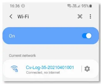
 Note: The network generated by the CV-Log-35 has no Internet access. Any error messages about this can be ignored.
 - Enter the address http://192.168.4.1 in your usual internet browser, or scan the following QR code using a QR code reading application:

- After a few seconds, the configuration interface of your CV-Log-35 will be displayed on the default browser.
- The home page displays the measured values in real time. It also contains the web browsing menu as well as other useful information of your CV-Log-35.
9.2 NAVIGATION MENUS
The user interface has dropdown menus to facilitate the readability of the interface.
To access sub-menus, click on the icon ![]() to the right of the menu if available.
to the right of the menu if available.
Menu without icon ![]() don’t have sub-menus.
don’t have sub-menus.
When you click on the icon ![]() , the other menus close.
, the other menus close.
To hide sub-menus, click on the icon ![]() to the right of the menu if available.
to the right of the menu if available.

9.3 SIMPLIFIED / ADVANCED MODE
The advanced mode allows accessing configuration parameters requiring specific knowledge.
![]() Do not access the advanced mode without prior training or assistance from CLA-VAL personnel.
Do not access the advanced mode without prior training or assistance from CLA-VAL personnel.
- To access the “ADVANCED MODE”, click on the icon
 at the top right of the interface.
- A pop-up will open to confirm your choice.
- Click on the “OK” button. You now have access to the advanced settings.
- Click the icon again to exit the advanced mode.
At the end of your session, the advanced mode will automatically be deactivated.
![]() Note: Some parameters require switching to “ADVANCED MODE”. These settings are indicated in the manual by the following icon:
Note: Some parameters require switching to “ADVANCED MODE”. These settings are indicated in the manual by the following icon: ![]() .
.
9.4 BASIC SYSTEM SETTINGS
- Click on the
 ” System” menu.
 - Give your CV-Log-35 a name.
- Select the language of the interface.
- Select your time zone using the “DETECT” button. If the time zone is not detected automatically, you can choose it manually with the “Time Zone” drop-down menu.

- Optional: Set the automatic synchronization of the unit’s internal clock.
a. Choose a time synchronization server (NTP server). The address pool.ntp.org, corresponding to a publicly accessible server, can be used if you do not know an alternative.
b. Periodic synchronization is recommended.
This operation can only be performed if the CV-Log-35 is connected to the cellular network (option). If not, go directly to step 8. - Click on “SAVE NTP INFORMATION” to apply the changes.

- Click on “SYNCHRONIZE NOW” to update your unit’s clock immediately.
This operation can only be performed if the CV-Log-35 is connected to the cellular network (option). If not, go directly to step 8. - Check that the time displayed on the clock under the navigation menu is correct. If not, you can manually set the time in “Manually set date and time”. Click on “SET DATE AND TIME” to have the change applied.

9.5 INPUT: COLOR CODING
A color code is used to indicate whether an input has reached its alert threshold or if the input has been forced to a predefined value by the user.
When an input reaches its alert threshold, its value appears in red.
When the input is forced, the value appears in dark blue.

9.6 ANALOGUE INPUT SETTINGS
9.6.1 CONFIGURATION
The inputs identified by AI1, AI2, AI3 and AI4 are analogue inputs.
- Click on “
 Inputs” to display the input configuration page.
- To activate an input that is not displayed on the list, select “Show disabled ports”. The list will show disabled inputs with a gray background.
- Click on an input to reach its configuration page.

- On the configuration page of the desired input, you have the possibility to change the name, and then configure the basic settings of the connected sensor.
- , additional sensor settings are available in “advanced mode”.
- , “Lost Signal” drop-down menu allows to configure an action when the sensor signal is lost. For example, when the ratiometric sensor voltage is less than 0.5 V.
You have the choice between:
a. No Value
b. A default Value
c. The last Value - When done, click “SAVE” to apply your changes.

9.6.2 INPUT TEST
To test the proper functioning of an input, you can override its value:
- After defining a desired value, click on “OVERRIDE”, the forced value takes priority over the sensor.
- To cancel the input override, click on “CANCEL”.
When you exit the “Configuration” mode, all overridden inputs are automatically released.

9.7 CONNECTING A FLOWMETER
Pulse meters must be connected to digital inputs (DI1 or DI2). The configuration of these inputs DIx is broken down into two sub-inputs: DIxC, which provides volume information (C=COUNTER), and DIxF, which is flow rate information.
The input DIxC controls the display of the volume measurement.
- Select the “pulse weight” for the flow meter and its units.
- Set the initial value of the counter.
- Click “SAVE” to apply the changes.

The input DIxF controls the flow rate display.
- Choose the pulse weight and its units. These options must match the connected flowmeter.
- Choose the units in which the flow rate is displayed.
- Set the maximum measurement value of the input.
• You can set the timeout before signal loss.
• The “Signal Lost” dropdown menu allows you to configure an action when the sensor signal is lost. For example, when the voltage of the ratiometric sensor is less than 0.5 V. You have the choice to apply:
a. No value
b. A default value.
c. The last value.- Click “SAVE” to apply changes.

9.8 EVENT SETTING
Events are used to set alerts.
You can set two types of alerts:
- The high alarm is used to detect values above a threshold.
- The low alarm is used to detect values below a threshold.
Alerts can be used to force data to be sent before the regular transmission time.
- Click on “
 Events”
 - Click on the input you want to configure.
- Select the threshold and return to normal value. Return to normal allows defining a dead band, avoiding oscillations between the active and inactive state.
- Click “SAVE” to apply the changes.

9.9 VALVEFLOW™ SETTING (OPTION)
The ValveFlow™ allows calculating the flow through a CLA-VAL valve, thanks to inlet pressure, outlet pressure, and valve opening.
- Configure the ValveFlow by clicking on “
 ValveFlow™“.
 - Select the inputs corresponding to the inlet/outlet pressure, as well as the opening.
- Select the type of valve installed.
- Click “SAVE” to apply the changes.

9.10 CUSTOM SIM CARD (COMMUNICATION OPTION)
- Click on “
 Connectivity” menu.
 - Enter the APN information of your SIM card (provided by your network operator).
- Choose whether you want to communicate in 4G / 2G (Fallback in 2G in case of unavailability of 4G), 4G only, or 2G only and the 4G technology (CAT-M1 or NB-IoT).

- Click the “SAVE” button in the “SIM card settings” section to apply the configuration.

9.11 CHECKING THE QUALITY OF THE NETWORK (COMMUNICATION OPTION)
- Click on “ Connectivity” menu.
- Click on the button “TEST CONNECTION”.

- Wait until the mode is online and refresh the page (F5).
- Check the dBm value by hovering over the network quality icon.

9.12 REGISTER ON LINK2VALVES (COMMUNICATION OPTION)
Link2Valves™ is the CLA-VAL web platform (https://cla-val.ch) that allows the remote access to your CV-Log-35.
A Link2Valves account is necessary. Please contact CLA-VAL to get one for free if you don’t have it yet.
- Click on “
 Transfers” menu.
 - Under “Transfer List”, click “Link2Valves”.

-
Choose the transfer interval and the time when the transfer will start. This interval will determine the frequency of communications of the CV-Log-35 and Link2Valves. Please note that a faster interval will have a negative impact on the battery life and generate potential additional data communication costs.

-
Associate the CV-Log-35 unit with your Link2Valves user account. First, enter the email address of your Link2Valves account. If you do not have one, please contact CLA-VAL to get one for free. Then click on “REGISTER NOW” and wait for the message “Success! “.

-
Don’t forget to click “SAVE” for your changes to takse effect.
9.13 PEERING LINK2VALVES
The HTTPS Peering functionality enables two or more CV-Log-35 devices to connect, communicate, and exchange information with each other. This feature is especially useful in scenarios where measurements are taken far from the valve, such as when the reservoir is located remotely. In such cases, the CV-Log-35 positioned near the reservoir measures the level and sends this value to the CV-Log-35 controlling the valve. Based on these values, the controller activates the actuator to reach the desired setpoint.

To use this feature, the devices intended to communicate must be connected via Link2Valves.
The first step is to configure the Peering functionality on L2V. To do so:
- From the main Link2Valves page, click on the Peering option.

- Click on “Add Subscription” to create a new communication between the two devices.
- Select the device that will publish the data and the device that will receive the data.
- Choose the inputs to be transmitted to the other device. For the publishing device, it is also possible to publish its outputs.
- Finally, click the “Add Subscription” button.

After configuring HTTPS Peering on Link2Valves, the next step is to set up the CV-Log-35 devices so they can communicate with each other.
To configure Peering on the CV-Log-35, follow these steps:
- Access the Peering submenu from the Settings menu.

- In the Publication section, configure the device that will publish its data. Enable publishing and select the publishing interval.
 Reminder: A higher publishing frequency may lead to increased network data usage and battery consumption.
 - In the Subscription menu, configure the device that will receive the data.
a. Click the Refresh button to search for publishing devices, then click to enter the menu of the publisher from which the data will be collected. b. After selecting the publisher, choose the data refresh interval and set the timeout duration in case no data is available.
 c. Click “Add” and then click the button to add the channels you wish to subscribe to.
 By completing these steps, the CV-Log-35 devices will be able to communicate effectively via HTTPS Peering.
9.14 LOGGING SETTING
- Click on “
 Logging” menu to access the corresponding configuration page.
 - Choose a recording interval. This interval manages the periodic recording of all activated inputs.
- Click “SAVE” to apply the changes.

9.15 BATTERY CONTROL
The battery display estimates the remaining time of the battery.
- During battery replacement.
- Click on the “RESET BATTERY” button to reset the battery display.
This button resets the battery life statistics and should only be used after a battery has been replaced. - If you are not using a battery, you can disable the battery display by clicking on the “Use an external power supply” button.

9.16 FIRMWARE UPDATE
- Click on to enter to the advanced mode.
- Click on the “ System” menu.

- Click on the “Upload firmware – Choose a file” submenu, then choose the ZIP file for example “CVLOG35_2.3.2.tar”.

- Click on the “UPLOAD FIRMWARE” button and wait for a minute.
- When the loading of the firmware is ok. Click on the “REBOOT NOW” button and wait a few minutes. During the update, The LED will blink purple. Do not disconnect the power during this time!

- When the update is completed, the CV-Log-35 will return in “Configuration” mode and the LED will blink blue.
After some minutes of inactivity, the CV-Log-35 will exit from the “Configuration” mode and enter “Acquisition” mode.
![]() Note:
Note:
On the CLA-VAL website (https://cla-val.ch). It is possible to download the latest version of the software & firmware.
SUPPORT
10.1 MAINTENANCE AND RETROFIT
The CV-Log-35 is maintenance-free over the entire battery lifetime, which depends on the measurement and transmission frequencies settings (remotely configurable). However, environmental conditions may shorten battery lifetime and the presence of humidity inside the housing lead to corrosion. Prevent these situations with clean and robust installations.
When the battery reaches its end-of-life, ask CLA-VAL, or an authorized reseller for maintenance assistance to change the battery, update the device to the most current Firmware, and test the system.
10.2 NON-CONFORMITY RETURN (NCR)
Only return CV-Log-35 under warranty after attribution of an Equipment Return Authorization provided by CLA-VAL. The returned CV-Log-35 must be clearly marked with the Non-Conformity (NCR) number.
ACCESSORIES
![]() Warranty may be void if accessories other than those recommended by CLA-VAL are used.
Warranty may be void if accessories other than those recommended by CLA-VAL are used.
| Parts | Order Code | Description |
 |
MEXE-B11-02 | Internal battery replacement |
 |
MEXE-B11-01 | External High-Capacity battery replacement |
CLA-VAL Europe www.cla-val.ch
cla-val@cla-val.ch
29 – CLOG35UE E 02/25
© Copyright CLA-VAL Europe – Specifications subject to change without notice – no contractual illustrations.
Reduce your waste – Sort your rubbish
Documents / Resources
 |
CLA-VAL CLOG35UE Communicating Data Logger [pdf] User Manual CLOG35UE, CLOG35UE Communicating Data Logger, CLOG35UE, Communicating Data Logger, Data Logger, Logger |