CHANNEL ORB-R-RS4-OLED Disabled Refuge Emergency Voice Communication System User Manual

ORB-R-RS4/8/OLED — Commissioning / User Manual. Revision 5
Safety Information
![]() Observe all safety information on the product labels.
Observe all safety information on the product labels.
ESD Precautions
This product contains static-sensitive devices. Observe ESD precautions when working on the equipment with the cover / door removed.
![]()
Introduction
This commissioning manual provides general guidance for the operation, configuration, commissioning, maintenance, and fault finding of the ORB-L-RS4 (RS8) (RS16) -OLED. The disabled refuge system has been manufactured to comply with BS5839 Pt9. Disabled Toilet Alarm has been manufactured to comply with BS8300.
Emergency voice communication systems (EVCS) allow fire fighters and others to communicate with one another during emergency situations in and around buildings and at sports and similar venues.
Emergency voice communication systems are used in connection with life safety and need, therefore, to be subject to high standards of design, manufacture, installation and servicing, similar to those covering fire detection and alarm systems and voice alarm systems.
Terms and definitions:
Competent person
Authorised person with the necessary training and experience, and with access to the requisite tools, equipment and information, and capable of carrying out a defined task.
Disabled refuge system
A disabled refuge system enables communication between strategic points throughout the building or site and the central control point(s). EVCS systems are generally needed for disabled people who may have difficulty negotiating the evacuation route. The need for EVCS in any specific building or complex will normally be determined by the appropriate regulation and/or a fire risk assessment carried out by the owner, landlord, occupier(s), employer(s) or other competent person, as appropriate.
Outstation including a disabled refuge hands free unit. (Type B)
Combined outstations including a fire fighting telephone handset and a disabled refuge hands free unit. (Type C)
Fire telephone system
Commonly-used with fire fighters to form an emergency voice communication system that includes telephone handsets (Type A) at outstations and wired in enhanced fire rated cable.
Combined outstations including a fire fighting telephone handset and a disabled refuge hands free unit. (Type C)
Refuge area
Area that is enclosed with fire-resisting construction (other than any part that is an external wall of a building) and served directly by a safe route to a storey exit, evacuation lift or final exit, thus constituting a temporarily safe space for disabled people to await assistance for their evacuation.
Installation
:(refer to Dwg. C51313/E)![]()
Install central enclosure, with cable entry gland at top, at a height of approx. 1.5 metres above floor height. Ensure fixings can support a load of 20 Kg.
The field cabling described below must be installed via top entry to the enclosure.
The system batteries will sit on the lower edge of the enclosure, and the entire space below the main PCB assembly must be kept clear to accommodate these items.
Connect Field Cabling
A – Mains Power Connect 5A (lighting rated) A.C. Mains supply (220 – 240V) to appropriate (L)ive, (N)eutral and (E)earth terminals on the modular PSU unit DSP60, located on DIN Rail fixings at the right of the main enclosure (Max system load is 40 Watts).
N.B. Earth terminal must be connected to building earth.
B1 & B2– Connect 2 core (+ screen) enhanced fire rated cable out to each remote outstation location.
Observe colour coding on PCB ident for cable cores:
BN (Brown) + : PWR (+ 24VDC)
BU (Blue) – : DAT (Data / Line)
Screen SCN : Cable screen (connected to system earth and COM internally)
This cable is then connected, in a ‘Radial’ configuration; each remote outstation is required to have the same address as the terminated location on the main control panel.
i.e.
Unit 1 Address 01 : to terminals ‘REMOTE 1’ on CS1007.
Unit 4 Address 04 : to terminals ‘REMOTE 4’ on CS1007.
The PCB sub-assembly CS1008 located in the back box of each remote location must continue to observe colour coding as listed above.
C – Fault Out – Volt free changeover contacts, for remote fault reporting.
D1 – Call On System – Volt free changeover contacts – changes state with any call on the system.
Use if remote call indication is required. Including an AUX 24 volt supply to power remote indicators units. RBU24.
D2 – Toilet Active – Volt free changeover contacts – changes state with any toilet active on the system. Use if remote indication is required. Including an AUX 24 volt supply to power remote indicators units. TBU24.
The following connections are optional, and are fitted only when the system specification requires these functions
E – Anti-Tamper (Fire inhibit) Short these terminals with a volt free closing contact (rated 50mA or higher) to enable the system ‘Anti Tamper’ feature.
(The ‘Anti Tamper’ feature enables the system to automatically disable incoming calls, whilst retaining system monitoring of the remote cabling and outstations. The system is returned to full operation with this contact opened). Toilet alarm inputs are not effected.
SETUP – Switch F
The setup switch is used for commissioning the system.
Main Display Connector J
The Cat5 (RJ45) socket is only used for the master control panel. These are intended to be connected via standard (non fire rated) UTP Cat 5 cable, to the main control panel.
Repeaters Connector K
The Cat5 (RJ45) socket is only used where a remote control panel (repeater) is fitted. These are intended to be connected via standard (non fire rated) UTP Cat 5 cable, to a cable junction box adjacent (within the same fire zone) to the main control panel.
From that location, the control functions are serialised, and forwarded to the remote control panel location via a four pair (+screen) enhanced fire rated cable.
To monitor the repeater panel remove L17 on the CS1007.
Flush mounting bezel assembly

Surface mounting sleeve assembly

Commissioning procedure (refer to Dwg. C51313/C)
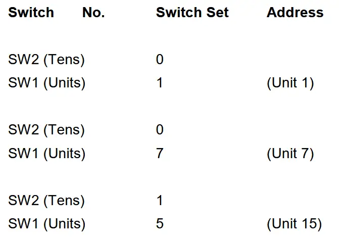
Remote Outstation Addressing
![]()
Remote outstation addressing: CS965. Each outstation requires an address which relates to the switch position on the master control panel.
SW1 & SW2 are located on CS965 as below.

Batteries
Fit battery loom as indicated on this drawing. C51313/E
CHECK RED LEAD IS CONNECTED TO THE RED (+) BATTERY TERMINAL. CONNECTING THE BATTERY LEAD WITH REVERSE POLARITY WILL DAMAGE THE EQUIPMENT.
![]()
Remote outstation radial wiring tests
The following measurements are required before applying A.C power to the system:
BN (Brown) + : PWR (+ 24VDC)
BU (Blue) – : DAT (Data / Line)
Screen SCN : Cable screen (connected to system earth and COM internally)
Apply A.C. Power to the system
Check before power up that the master control panel RJ45 connector is plugged into connector J.
Plug the two way cable loom terminal to the ‘Batt. +/-‘ terminals, located at the lower right edge of the main control PCB type CS1007. (N.B. note that the system will not power up, until A.C. power is applied).
On power up the system will display all faults. Pressing the Lamp Test / Silence Fault button will mute the fault sounder. All control panel zone switches will illuminate in time with the fault indicators.
![]()
Setup
Press and hold the setup button (F) on CS1007 until the setup switch illuminates. This can take up to ’10’ seconds. The front control panel will sound three times to signify that the system is in a setup mode.
In this mode the system will send out addresses for all eight outstations. With a response from an outstation a solid illumination will appear on the front control panel. Once all out- stations are correctly displaying on the control panel front the system unit set is ready.

The front control panel will sound twice to signify that the system has come out of the setup mode.
Setup LCD
Press and hold the setup button (F) on CS1007 until the setup switch illuminates. This can take up to ’10’ seconds. The front control panel will sound three times to signify that the system is in a setup mode.
The LCD screen will change to SETUP ACTIVE TEXT EDIT as below. The high- lighting * stars * indicate the menu selection. With the right and Left buttons a selection can be made for zone text edit for Disabled Refuge or Toilet Alarm. Pressing the enter button selects the desired option.

Pressing the right or left buttons allows the disabled refuge zone number to change to the desired text location to edit. As the system is in setup the responding or active remote outstations will be displaying on the 1-16 zone buttons above the LCD screen. These same zone numbers refer to the text locations required for each zone.
Pressing the enter button allows text editing of disabled refuge zone 01.
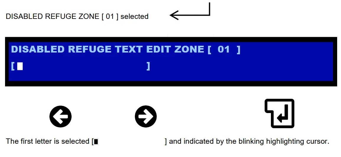
Pressing the left or right button allows the letter to be changed in the cursor. Once the correct letter is found, press the enter button to select the letter and move to the next letter location.
If the enter button is pressed without any letter selected a space is automatically selected.
The following Letters and symbols are available to create the custom descriptions for the disabled refuge or toilet alarm locations.

Once the description is complete, press the enter button until the highlighting stars return to the zone number selection [ * 01 * ] To edit the next disabled refuge zones text use the left and right buttons to scroll to the next desired zone number.
To exit the text edit mode exit setup by ;
Press the setup button (F) on CS1007 until the setup switch illumination goes out. The front control panel will sound twice to signify that the system has come out of the setup mode.
Please note the text edit will not exit until the current zone has been completed and has returned to the zone number selection.
Setup LCD Toilet Alarm
To text edit the toilet alarm zone text the same process is required as the disabled refuge before.
Press and hold the setup button (F) on CS1007 until the setup switch illuminates. This can take up to ’10’ seconds. The front control panel will sound three times to signify that the system is in a setup mode.
The LCD screen will change to SETUP ACTIVE TEXT EDIT as below. The highlighting * stars * indicate the menu selection. With the right and Left buttons a selection can be made for zone text edit for Disabled Refuge or Toilet Alarm. Pressing the enter button selects the desired option.

Pressing the right or left buttons allows the toilet alarm zone number to change to the desired text location to edit. As the system is in setup the responding or active remote outstations will be displaying on the 1-16 zone buttons above the LCD screen. These same zone numbers refer to the text locations required for each zone for each toilet that is wired to its local refuge point.
The same process as the disabled refuge will allow different zone location text to be entered for the toilet alarm zone.
Setup LCD Erase All
Press and hold the setup button (F) on CS1007 until the setup switch illuminates. This can take up to ’10’ seconds. The front control panel will sound three times to signify that the system is in a setup mode.
The LCD screen will change to SETUP ACTIVE TEXT EDIT as below. The highlighting * stars * indicate the menu selection. With the right and Left buttons a selection can be made for zone text edit for ERASE ALL. Pressing the enter button selects the desired option.

The LCD screen will change to ERASE ALL as above. The highlighting * stars * indicate the menu selection. With the right and Left buttons a selection can be made for [NO] [YES] ERASE ALL. Pressing the enter button selects the desired option.
To exit the text edit mode exit setup by ;
Press the setup button (F) on CS1007 until the setup switch illumination goes out. The front control panel will sound twice to signify that the system has come out of the setup mode.
Setup Toilet Alarm TAB and TAI units
The (TAB) Toilet alarm input card provides radial spur connections for the Hark toilet alarm kits. In most cases the toilet alarm kit is wired to a local refuge point. However there are times where the toilet alarm ‘2’ core spur from the Over door / PSU unit is wired directly back to the master control panel.
In the central instance you would fit either a TAB4, TAB8 or a TAB16 radial input card. This card fits directly onto the main control board in the rear of the control panel. This will fit onto either a CS1007 or CS911 card. Pillars are already fitted to these boards ready to accept the TAB card. Before fitting the card remove ALL power to the system. Please take static precautions when handling any of the cards to avoid giving static damage to cards. The TAB card is supplied with a RJ45 connection lead. This plugs directly into the rear main control board. CS1007 (J11) or CS911 (J9). Once the lead is connected between the two cards secure the TAB card to the pillars with the 4 off M3 x 6mm screws.
Now that the card is fitted you will need to change L2 on the main control rear board to the B position. As default the link is fitted in the A position.
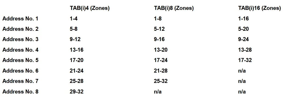
Please select the correct address for the TAB (TAi) from the list below;
The cabling from the toilet alarm kits can be wired into the appropriate input terminals marked 1 to 16. These connections are polarity conscious. Once all of the above is carried out the power can be re-instated and the batteries.
The system will have to be run through the standard set up procedure.
Press and hold the setup button (F) on CS1007 until the setup switch illuminates. This can take up to ’10’ seconds. The front control panel will sound three times to signify that the system is in a setup mode.
In this mode the system will send out addresses for the TAi or TAB units. Each unit has two red led’s that will flash from data (IN) to data (OUT) approximately every 6 seconds. This signifies that the TAI unit is logged onto the system. Whilst in setup mode check that all disabled refuge units are still responding on the front panel with solid zone indications.
Once all TAI units and outstations are correctly displaying exit setup. By pressing button (F) on CS1007
System Test
Once the installation and commissioning procedures are complete, test for correct system operation, and fault reporting functions. Test all locations for correct call in / call out functions, by following the user manual instructions listed on page 20 Section 4.
Remove primary power, to check correct operation of battery support supply. Central control will report a fault condition. The fault sounder will be activated on the main control panel, and the fault LED’s will be illuminated with a slow flash pattern.
The fault out relay will be de-energised.
Press the ‘silence fault / lamp test’ switch on the control panel momentarily, to silence the fault sounder to an intermittent state. Open the main enclosure to confirm display of the ‘mains fail’ and ‘charge fail’ fault LED’s located near the bottom edge of the main PCB ref. CS1007. Reconnect primary power. To reset the fault press and hold setup button (F) until the fault clears from CS1007.
Please note that use of the anti-tamper (fire inhibit) facility is not recommended in BS5839 Pt9.
Where utilised, if the system is to be tested without the fire system active ensure that the anti-tamper (fire inhibit) is disconnected or open circuit. To check the function of the anti-tamper any call made from a remote hands free outstation will be automatically cancelled by the central controller. The system will remain inactive from remote calling for c.10 seconds, to minimise nuisance recalling.
An open circuit at the anti-tamper terminals will allow normal system operation.
Note that making a call out from the master is not effected by the anti-tamper status.
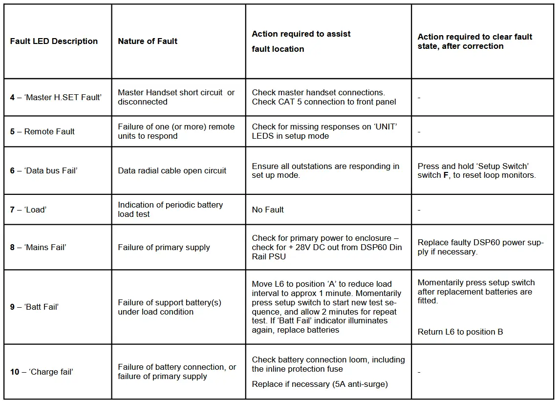
Fault Indications (refer to Dwg. C51313/E)
The LED function references on Dwg. C51313/E, and on PCB CS1007, identify the function of all fault indications within the central enclosure. Note that any fault condition will cause the front panel fault Light Emitting Diodes (LED’s) to indicate with a slow flashing pattern, and will activate the audible fault sounder as a continuous tone.
Pressing the ‘Lamp Test / Silence Fault’ switch will change the sounder function to intermittent. (A short ‘reminder’ bleep approx every 90 seconds). Generation of a second fault condition will reactivate the fault sounder to a continuous tone.
The following table lists the various fault LED’s, and describes the action to be taken to help identify specific faults.
L4 – Programming enable (FITTED TO POSITION A)
L5 – Fit to disable battery load timer (NOT NORMALLY FITTED)
L6(A) – Fit enable shortened (c. 1 minute) battery load timer (Test setting)
L6(B) – Fit to enable battery load timer (Normal setting)

User Manual
User Master Handset to Make a Call
The Central Control Panel consists of a single master telephone handset, and an array of momentary illuminated switches, one of which is assigned to each remote outstation during system commissioning.
Where these are identified on the Control Panel with simple numeric indications, a LCD screen provides zone text descriptions for each disabled refuge location.
Lifting the master handset will clear any faults present on the system. The LCD screen will change to the screen below which indicates that the system has no zone location text entered.
The setup procedure 3.5 is required before zone information can be displayed.

Once Setup 3.5 procedure has been completed, lifting the master handset will display the edited zone descriptions for each zone. Each zone location can be scrolled by pressing the left and right buttons.
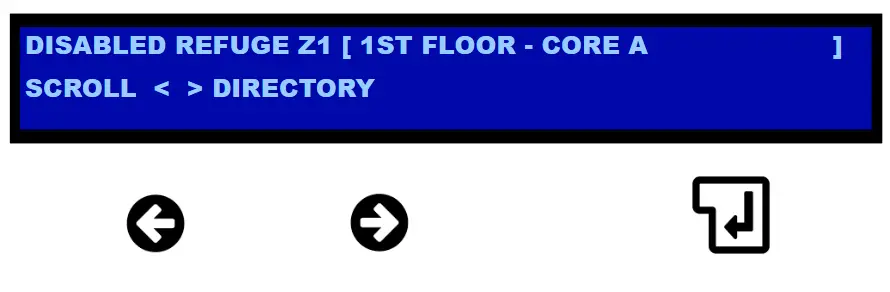
Once the disabled refuge zone has been selected, press the corresponding zone button number will connect the outstation to the master handset.
User Master Handset to Receive a Call
The Central Control Panel consists of a single master telephone handset, and an array of momentary illuminated switches, one of which is assigned to each remote outstation during system commissioning.
Where these are identified on the Control Panel with simple numeric indications, a LCD screen provides zone text descriptions for each disabled refuge location.
When a call is present on the system from an outstation pressing its call button, the master handset will ring with a conventional ‘double pulse’ ring tone.
The panel switch associated with the particular outstation zone will start to flash, in time with the ring tone. The LCD screen will display the zone number and location text for the calling in outstation.

The call is answered by lifting up the master handset, and momentarily pressing the flashing zone switch. The switch illumination will change to a solid state and you will hear a re-assurance ‘beep’, the ringer will cease, and the call will be routed through to the remote outstation.
Once the routing is complete, an audio path is established, and a two way full duplex conversation may take place, between the master handset operator, and the remote outstation. The call is cleared by replacing the master handset onto its cradle switch. This action will also clear the call status of the remote outstation automatically.
User Master Handset to Receive Multiple Calls
In the event that the system is already in use, and a second remote outstation calls in, then the calling remote outstation will continue to hear the double pulse call tone. The associated call switch on the central control panel will begin to flash with a ‘busy’ pattern (c. 0.5 seconds on/off). There is no audible indicator of the additional call(s) at the central panel.
The LCD screen will change to show the number of calls on the system [ 3 ] CALLS WAITING. Pressing the left or right buttons will scroll through the active call zone descriptions.

The central control operator may either press this ‘busy’ indicating switch, whilst maintaining the cur- rent call status, so that the switch illumination goes solid, and the newly selected remote outstation is added to the audio buss, permitting a three way conversation to take place.
Alternatively, the central control operator may prefer to clear the first call, by replacing the master hand set onto its cradle, and then ‘pick up’ the second call by lifting the master handset again, and pressing the flashing ‘busy’ switch.
Note that a maximum of up to 4 outstations should be connected at any one time. This can cause confusion as to who is being spoken to. In practice it is usually found that two is a more suitable operational limit.
Once the routing is complete, an audio path is established, and a two way full duplex conversation may take place, between the master handset operator, and the remote outstation. The selected calls are cleared by replacing the master handset onto its cradle switch. This action will only clear answered calls. Unanswered calls will automatically call back in.
User Remote Outstation Call – To Make a Call to Central Control
Press the CALL button on the front of remote outstation.
The ‘CALL REGISTERED’ LED will light, and a standard ‘double pulse’ call tone will be heard from the panel loudspeaker.
(N.B. If the system is already in use, a call tone will be heard as above until the Operator connects the call. The master control panel will register that a second call has been made. The main operator can then decide on whether to answer the second call together with the call already in use or to hang up and have private conversation with the new call.
Once the call is picked up at the central control station, it is then possible to hold a two way conversation with the controller. Speak slowly and clearly, at a distance of no more than 1 metre from the out- station, for best results.
At the conclusion of the call, the remote outstation call status will be reset automatically by the central control panel.
Fault Conditions
There are a number of fault states to which the central control equipment responds. At the outset of a fault condition, the internal control panel fault sounder will sound, and the two front panel ‘fault’ LEDs will flash with a slow (c. 2 seconds on / 2 seconds off) pattern.
The LCD screen will change to ;

In the event that the fault is with a specific outstation, the appropriate call switch on the main control panel will also flash with the same pattern.
In the event that the fault condition is no location specific, then examination of the fault LED status internally within the control panel is required. This task should be carried out by suitably qualified service personnel. There are no user serviceable parts inside the central control enclosure.
To silence the fault sounder, momentarily press the ‘LAMP TEST / SILENCE ALARM’ switch on the control panel. Note that this action will only silence the fault sounder, and not clear the fault condition.
The occurrence of a further fault condition will restart the fault sounder.
All fault conditions should be reported to the service agent as soon as possible.
User Master Handset to Receive a Toilet Alarm
When a toilet alarm is present on the system from a pull cord being pulled. The sounder will sound to draw attention to the master panel. The lamp test button can be pressed to mute the sounder whilst investigating the alarm. The sounder will resound every 2-3 minutes until the alarm has been reset at the toilet locations.
The LCD screen will indicate the zone and text location.

Multiple toilet alarms will show as the number of active toilets. [ 2 ] ACTIVE TOILETS

Pressing the left or right buttons will scroll through all active toilet alarms.
If a disabled refuge call is made or the master handset is lifted, the system will automatically prioritise the disabled refuge functions over the toilet alarm. The toilet alarm will reinstate once the disabled refuge call has cleared or the master handset s replaced.
Documents / Resources
 |
CHANNEL ORB-R-RS4-OLED Disabled Refuge Emergency Voice Communication System [pdf] User Manual ORB-R-RS4-OLED, ORB-R-RS8-OLED, ORB-R-RS4-OLED Disabled Refuge Emergency Voice Communication System, ORB-R-RS4-OLED, Disabled Refuge Emergency Voice Communication System, Refuge Emergency Voice Communication System, Emergency Voice Communication System, Communication System, System |